STANDARDS ACT: INDEX TO SUBSIDIARY LEGISLATION
Zambia Bureau of Standards (Standards and Certification Marks) Regulations
Zambia Bureau of Standards (Calibration Service) Regulations
Standards (Imports) (Quality Monitoring) Regulations
Standards (Compulsory Standards) (Declaration) Order, 2003
Standards (Compulsory Standards) (Declaration) Order, 2009
Standard (Compulsory Standards) (Declaration) Order, 2010
Standard (Compulsory Standards) (Declaration) Order, 2011
Standards (Compulsory Standards) (Declaration) (No. 1) Order
Standards (Compulsory Standards) (Fees) Regulations
Standard (Compulsory Standards) (Chalk) (Declaration) Order
Standards (Compulsory Standards) (Declaration) Order, 2013
Standards (Compulsory Standards) (Declaration) Order, 2017
STANDARDS (STANDARDS AND CERTIFICATION MARKS) REGULATIONS
[Section 37]
Arrangement of Regulations
Regulation
1. Title
2. Interpretation
3. Authority
4. Application for authority
5. Inspection
6. Condition of authority
7. Periodic inspection
8. Declaration of dispute
9. Register of authorised persons and products
10. Inspection of register
[Regulations by the Minister]
SI 72 of 1994.
These Regulations may be cited as the Zambia Bureau of Standards (Standards and Certification Marks) Regulations.
In these Regulations, unless the context otherwise requires—
“authority” means the written authority obtained from the Bureau to apply a certification mark;
“authorised person” means a person who has been granted authority to use a certification mark;
“inspection” includes the process of examining and conducting of relevant tests by the Bureau to determine the conformity of any commodity with a declared standard.
The written Authority referred to in section 14(1) of the Act shall be in Form ZABS/1 set out in the Schedule.
An application for use or renewal of authority shall be in Form ZABS/2 set out in the Schedule.
The Bureau shall not consider an application for an authority unless an inspector has been to the applicant’s premises and has together with the applicant completed Form ZABS/3 set out in the Schedule.
(1) The authority issued by the Bureau shall be subject to the following general conditions—
(a) the authorised person shall comply with the general and specific conditions and scheme of supervision and control which the Bureau may issue from time to time;
(b) the authority shall not be transferable;
(c) costs incurred by inspectors, to determine whether commodities to which a certification mark has been applied fulfil the applicable requirements laid down by the Bureau, shall be borne by the authorised person to the extent specified in the scheme of supervision and control for the commodities listed in the authority;
(d) the right to use a certification mark applies only to the commodities listed in the authority;
(e) costs incurred in applying a certification mark shall be borne by the authorised person;
(f) the Bureau reserves the right to revise the procedures for marking standardised commodities;
(g) if the declared standard on which the authority is based is revised, the authority shall be valid only if the authorised person agrees to comply with the requirements set out in the revised declared standard;
(h) the authority shall be valid for one year from the date of issue unless earlier revoked.
(2) The Bureau shall impose any other conditions on the Authority as it thinks fit.
The Bureau shall periodically send an inspector to the authorised person’s premises and the inspector shall complete Form ZABS/4 set out in the Schedule.
Any person aggrieved by the refusal of the Bureau to grant authority may within 21 days declare a dispute by completing Form ZABS/5 set out in the Schedule.
9. Register of authorised persons and products
The Bureau shall keep a register of all authorised persons and the products in respect of which an authority has been issued
Any person may, on payment of the appropriate fee, inspect the register.
FORM ZABS/1
THE REPUBLIC OF ZAMBIA
STANDARDS ACT
STANDARDS (STANDARDS AND CERTIFICATION MARKS) REGULATIONS
AUTHORITY TO USE A CERTIFICATION MARK
[Regulation 3]
No……………………….
This authority is granted to ………………………of ……………………………………………………to use the certification mark specified in Statutory Instrument No…………………of 19…………………, and in respect of ………………………………………………….………………….commodity/process which commodity/process conforms to ………………………………………………….…………………………declared standard or approved specification mark.
This authority is issued subject to the general conditions contained in the Zambia Bureau of Standards (Standards and Certification Marks) Regulations, 1987, and the following additional condition(s) …………………………………………………………………………………………………………………………………………………….
Date……………………………………………………
……………………………………………………
Director
FORM ZABS/2
THE REPUBLIC OF ZAMBIA
STANDARDS ACT
STANDARDS (STANDARDS AND CERTIFICATION MARKS) REGULATIONS
APPLICATION FOR GRANT/RENEWAL OF AUTHORITY
[Regulation 4]
The Director, Zambia Bureau of Standards
1.
(a) Article……………………………………………………………………………………………………………………….
Type……………………………………………………………………………………………………………………………
Size…………………………………………………………………………………………………………………………
Grade……………………………………………………………………………………………………………………….
(b) Class of articles.……………………………………………………………………………………………………………..
Type…………………………………………………………………………………………………………………………
Size…………………………………………………………………………………………………………………………
Grade………………………………………………………………………………………………………………………
(c) Process ………………………………………………………………………………………………………
Only one of the three items under (a), (b) and (c) may be covered by one application.
Delete the other two.
(d) Related declared standard(s)
No. ………………………………… Title……………………………………..
No. ………………………………… Title……………………………………..
2. The above article(s) is/are manufactured by …………………………………………………………………………………………….……………………………………………………………………………………………………………carried out ……………………(factory) on the premises situated at …………………………………………………………………………………………….(address)
3. Production figures for the said article(s)/process and the value thereof to the best of my/our knowledge and estimates are as follows:
|
Year |
Production |
Unit |
Value K |
Last year from…………………. to………………………..
Current year from………………… to………………………
(estimates)
4. In order to ensure conformity of the said article(s)/process to the related declared standard(s)—
5. Should any initial enquiry be made by the Bureau I/We agree to extend to the Bureau all reasonable facilities at my/our command and I/We also agree to pay all expenses of the said enquiry, including charges for testing, as and when required by the Bureau.
6. Should the authority be granted and as long as it will remain operative, I/We hereby undertake to abide by all the terms and conditions of the Bureau and the Regulations prescribed under the Act. In the event of the authority being suspended or cancelled, I/We also undertake to cease with immediate effect to use the authority and to withdraw all relevant advertising matters and to take such other steps as may be necessary to fulfil the provisions of the Act.
Dated this……………………………day of………………………………………………………….
Signature…………………………………………………………………………………………
Name……………………………………………………………………………………………..
Designation………………………………………………………………………………………
For and on behalf of……………………………………………………………………………..
………………………………………………………………………………………(name of firm)
FORM ZABS/3
THE REPUBLIC OF ZAMBIA
STANDARDS ACT
STANDARDS (STANDARDS AND CERTIFICATION MARKS) REGULATIONS.
PRELIMINARY INSPECTION REPORT
[Regulation 5]
No………………………………………………………..
1. GENERAL INFORMATION
1.1 Applicant’s name…………………………………………………………………………………………..
1.2 Address……………………………………………………………………………………………………..
1.3 Situation of factory…………………………………………………. Telephone No…………………………..
1.4 Management Staff ……………………………………………………Person(s) Contacted
(i)
(ii)
2. PRODUCTION INFORMATION
2.1 Product name
2.2 Applicable declared standard
2.3 Type……………………………………………Size …………………………. Grade …………………….
3. RAW MATERIALS
3.1 Raw materials used—
(a)……………………………………………………………………………………………………
(b)……………………………………………………………………………………………………
(c)……………………………………………………………………………………………………
(d)……………………………………………………………………………………………………
3.2 Sources of supply—
(a)…………………………………………………………………………………………………….
(b)……………………………………………………………………………………………………..
(c)…………………………………………………………………………………………………….
(d)…………………………………………………………………………………………………….
3.3 Mode of receipt (batches, lots, nature of package)………………………………………
………………………………………………………………………………………………………………………
3.4 Test certificate of suppliers………………………………………………………………..
3.5 Arrangement for testing as received……………………………………………………..
3.6 Details of sampling………………………………………………………………………..
3.7 Methods of disposal of sub-standard raw materials………………………………………
……………………………………………………………………………………………………………………….
3.8 Record of tests with pro forma of records……………………………………………….
4. MANUFACTURE
4.1 Type/Grade being manufactured at the time of inspection—
(a) …………………………………………………………………………………………………..
(b) …………………………………………………………………………………………………..
(c) …………………………………………………………………………………………………..
4.2 Description of process from raw materials to finished product stage…………………………………
………………………………………………………………………………………………………………………
………………………………………………………………………………………………………………………
………………………………………………………………………………………………………………………
4.3 Intermediate points where control has to be exercised………………………………………………………
………………………………….………………………………………………………………………………
………………………………………………………………………………………………………………………
4.4 Details of records maintained and controls used……………………………………………………………
…………………………………………………………………………………………………………………………
4.5 Methods of disposal of sub-standard products………………………………………………………………
………………………………………………………………………………………………………………………
………………………………………………………………………………………………………………………
………………………………………………………………………………………………………..
4.6 Units of production…………………………………………………………………………………………………………………….
4.7 Production per day or per shift…………………………………………………………………………………………………………
5. PACKAGING AND MARKING
5.1 Nature of package in……………………………………………………………………………………………………………………
5.2 Quantity per packaging…………………………………………………………………………………………………………………
5.3 Marking on article………………………………………………………………………………………………………………………
5.4 Method of marking……………………………………………………………………………………………………………………..
(printing, stencilling, embossing, etc.)
5.5 Form of label(s) if any………………………………………………………………………………………………………………….
5.6 Batch or code numbering for identification…………………………………………………………………………………………….
6. LABORATORY AND INSPECTION
6.1 Details of staff………………………………………………………………………………………
………………………………………………………………………………………………………………….
6.2 Equipment and other facilities for complete specification testing…………………………………………………..
………………………………………………………………………………………………………………………………
6.3 Accuracy of instruments and arrangements for calibration………………………………………………..
………………………………………………………………………………………………………………………
………………………………………………………………………………………………………………………
………………………………………………………………………………………………………….
6.4 Any laboratory where the firm could test its products…………………………………………………………
………………………………………………………………………………………………………………………….
…………………………………………………………………………………………………………………………..
6.5 Records maintained in laboratory for routine tests………………………………………………………………
……………………………………………………………………………………………………………………………………..
6.6 Stages of processing where laboratory reports are made available………………………………………..
………………………………………………………………………………………………………………………………….
6.7 Sampling and testing of end products…………………………………………………………………………
…………………………………………………………………………………………………………………………………..
7. SAMPLE
7.1 Type, size and grade of the sample………………………………………………………………………………
…………………………………………………………………………………………………………………………..
7.2 Details of counter sample…………………………………………………………………………………………
………………………………………………………………………………………………………………………….
…………………………………………………………………………………………………………………………….
7.3 How sealed…………………………………………………………………………………………………………
……………………………………………………………………………………………………………………………..
7.4 Laboratory to which despatched…………………………………………………………………………………..
……………………………………………………………………………………………………………………………..
7.5 Test results on a sample if tested in factory……………………………………………………………………….
………………………………………………………………………………………………………………………………
7.6 Any further information regarding sample drawn………………………………………………………………….
………………………………………………………………………………………………………………………………………
7.7 Information regarding sample of other type/grade applied for…………………………………………………..
……………………………………………………………………………………………………………………………..
8. OTHER INFORMATION
8.1 Main buyers and selling price………………………………………………………………………………………..
…………………………………………………………………………………………………………………………….
8.2 Storage facilities…………………………………………………………………………………………………….
……………………………………………………………………………………………………………………………….
8.3 Hygienic conditions (in case of food products)……………………………………………………………………
………………………………………………………………………………………………………………………………………
8.4 Discussion with the firm on scheme of testing and inspection……………………………………………………
………………………………………………………………………………………………………………………………
9. CONCLUSION, RECOMMENDATIONS
………………………………………………………………………………………………………………………
………………………………………………………………………………………………………………………
………………………………………………………………………………………………………………………
Signature…………………………………………………………Inspected by……………………………………
Date……………………
FORM ZABS/4
THE REPUBLIC OF ZAMBIA
ZAMBIA BUREAU OF STANDARDS ACT
STANDARDS (STANDARDS AND CERTIFICATION MARKS) REGULATIONS
PERIODIC INSPECTION REPORT
[Regulation 7]
AUTHORITY NO……………………………………………………………………………..
1. AUTHORISED PERSON…………………………………………………………………
1.2 Address…………………………………………………………………………………..
1.3 Person(s) contacted…………………………………………………………………….
2. PRODUCT NAME…………………………………………………………………………
2.1 Date of inspection……………………………………………………………………….
3. PREVIOUS INSPECTION
3.1 Date…………………………………… Conducted by…………………………………
3.3 Conclusion and recommendation………………………………………………………
3.4 Action in advice rendered in previous inspection or otherwise asked for……………
4. Changes since previous inspection……………………………………………………….
………………………………………………………………………………………………….
4.1 TECHNICAL………………………………………………………………………………..
…………………………………………………………………………………………………..
…………………………………………………………………………………………………..
Authority No………………………………………
4.2 Administrative………………………………………………………………………………………………………
………………………………………………………………………………………………………………………
5. DESCRIPTION OF ARTICLE(S) BEING MANUFACTURED AT THE TIME OF INSPECTION
………………………………………………………………………………………………………………………
………………………………………………………………………………………………………………………
………………………………………………………………………………………………………………………
………………………………………………………………………………………………………………………………….
6. RAW MATERIALS
6.1 Name of major ones*………………………………………………Supplier*……………………………………
6.2 Does the firm test the major raw materials or does it depend on test certificates from suppliers?
……………………………………………………………………………………………………………………………………
6.3 Maximum and minimum values of principal requirements……………………………………………………
………………………………………………………………………………………………………………………………
6.4 Disposal of sub-standard raw materials…………………………………………………………………………
……………………………………………………………………………………………………………………………
7. PRODUCTION AND SUPPLY (from ………………………………………to………………………………………)
7.1 Quantity produced…………………………………………………….
7.2 Quantity marked……………………………………………………….
7.3 Quantity unmarked……………………………………………………
7.4 Reasons for not marking ……………………………………………….………………………………………………………………………………….
7.5 Parties supplies to ………………………………………………………………………………………………
………………………………………………………………………………………………………………………….
8. STORING, PACKING AND MARKING
8.1 Material held in stock……………………………………………………..
8.2 Condition of storing……………………………………………………….
8.3 Packing and marking on packages………………………………………
8.4 At what stage is marking done (after or before test results are known)…………………………………
*Attach list………………………………
Authority No………………………………
8.5 Any change in the marking procedure from approved one …………………………………………………………………………………………
9. PRODUCTION CONTROL
9.1 How is the control system operated? …………………………………………………………………………………………………………..
9.2 Variation in test results for principal requirements (append test results, if necessary or if required by the instruction sheet for the standard) ……………………………………………………………………………………………………………………
………………………………………………………………………………………………………………..
9.3 Are the test records maintained satisfactorily? …………………………………………………………………………………………………………………………………………….
9.4 What is the percentage of rejections, their reasons and manner of disposal? ……………………………………………………………………………………………………………………………………………..
9.5 Whether the failure is due to inherent causes or chance cause……………………………………..
………………………………………………………………………………………………………………….
10. TESTING IN FACTORY
10.1 Requirements tested with results (use laboratory pro forma) ……………………………………………………………………………………………………………………………..
10.2 Comparison of results obtained with firm’s records ..…………………………………………………………………………………………………………………………
10.3 Comparison of results with the requirements of the specifications ……………………………………………………………………………………………………………………………….
10.4 Are the instruments used calibrated periodically? ……………………………………………………………………………………………………………………………………………….
10.5 Are the instruments used reasonably accurate? ………………………………………………………………………………………………………………………………………………..
10.6 Any addition in the existing testing equipment? ………………………………………………………………………………………………………………………………………………..
11. SAMPLES FOR INDEPENDENT TESTS
11.1 Number of samples drawn …………………………………………………………………………………………………………………….
11.2 From where sampled? ………………………………………………………………………………………………………………………………………………..
Authority No………………………….
11.3 Code number/batch number/date of manufacture, etc., of the lot sampled and other markings …………………………………………………………………………………………………………………………………………..
11.4 Test record of the batch from which sample is drawn …………………………………………………….
……………………………………………………………………………………………………………………..
11.5 Samples brought in or left with the firm for despatch to testing laboratory ……………………………………………………………………………………………………………………………………..
11.6 Laboratory to which sample is sent/proposed to be sent …………………………………………………………………………………………………………………………………
11.7 Details of counter sample left with the firm ……………………………………………………………………………………………………………………………..
11.8 Any further information ………………………………………………………………………………………………………………………..
12. FOOD ARTICLES (indicate the hygienic conditions maintained in the factory)
……………………………………………………………………………………………………………………
………………………………………………………………………………………………………………………
13. CONCLUSION AND RECOMMENDATIONS
13.1 Has the scheme operated satisfactorily for this period since last inspected? ……………………………………………………………………………………………………………………………………………………
13.2 Assessment of the operation of the scheme based on the present vis-a-vis past performance ……………………………………………………………………………………………………………………………………………
13.3 Any discussion with the firm on any point of interest, e.g. any difficult in operation, irregularities observed in the operation ……………………………………………..…………………………………………………………………
13.4 Any action to be taken including suspension ……………………………………………………………………………………………………………………………….
13.5 Any other observations/comments ……………………………………………………………………………………………………………………………..
File Ref.
SIgnature………………………
Date…………………………..
Authority No…………………
REMARKS OF THE REVIEWING OFFICER
………………………………………………………………………………………………………………………………………………………………………………………………………………………………………………………………………………………………………………………………………………………………………………………………………………………………………………………………………………………………………………………………………………………………………………………………………………………………………………………………
FORM ZABS/5
THE REPUBLIC OF ZAMBIA
STANDARDS ACT
ZAMBIA BUREAU OF STANDARDS (STANDARDS AND CERTIFICATION MARKS) REGULATIONS, 1987
DECLARATION OF A DISPUTE
[Regulation 8]
To: The Director, Zambia Bureau of Standards
*I/We, ………………………………………………………………………………………………………………….carrying on business at ……………………………………………………………………………………………………………. (full business address) under the name of …………………………………………………………………………(full name of individual or firm) hereby, pursuant to the provisions of section 25(2) of the Zambia Bureau of Standards Act, declare a grievance stated hereunder: ……………………………………………………………………………………………………… ………………………………………………………………………………………………………………………………………………………………………………………………………………………………………………………………
(Here state the facts concisely in numbered paragraphs)
*I/We, the said ………………………………………..………………………………………………………………..do hereby refer the said matters in grievance to the Arbitrators.
Dated this……………………………………………………..day of………………………………………………………..
Signature………………………………………………………
Name…………………………………………………………..
Designation………………………………………………………..
For and on behalf of……………………………………………………………….(Name of firm)
*Delete as applicable
ZAMBIA BUREAU OF STANDARDS (CALIBRATION SERVICE) REGULATIONS
[Section 31]
Arrangement of Regulations
Regulation
1. Title
2. Interpretation
3. Categories of instruments and equipment to be calibrated
4. Documentation received with instrument
5. Re-calibration of measuring instrument
6. Information required
7. Calibration certificate
8. Penalty
[Regulations by the Minister]
SI 72 of 1994.
These Regulations may be cited as the Zambia Bureau of Standards (Calibration Service) Regulations.
In these Regulations, unless the context otherwise requires—
“bureau” means the Bureau established by section 3 of the Zambia Bureau of Standards Act;
“calibration” means all stages of any process aimed at or determining the degrees of the errors of a measuring instrument, as well as, where necessary, for the purpose of determining other metrological properties;
“measuring instrument” includes any device such as a graduated rule, set of weights, equal-arm balance, U-tube manometer, clock, ammeter, and others intended for the purpose of measurement and which may reproduce one or more known values of a given quantity, or provide an indication of the value of the measured quantity of equivalent information or which combines these functions;
“metrology” means the field of knowledge concerned with measurements and includes theoretical and practical aspects of measurements, at whatever level of accuracy, and in whatever fields of science or technology they occur;
“primary standard” means a standard which has the highest metrological qualities;
“standard” means a material measure, measuring instrument or system such as the one kilogram mass, standard gauge block, the 100 ohm standard resistor, the standard ammeter, the caesium atomic frequency standard and others, intended to define, realise, conserve or reproduce a unit or one or more known values of a quantity in order to transmit them to other measuring instruments by comparison;
“traceability” means the ability to trace the calibration of a measuring instrument to a more accurate and recognised standard.
3. Categories of instruments and equipment to be calibrated
(1) The Director shall, by notice, in the Gazette prescribe the categories of instruments and equipment which shall be calibrated by the Bureau and shall on that notice state—
(a) the date by which all instruments and equipment within that category shall be calibrated;
(b) the Standard to be used for calibration;
(c) the interval between each calibration; and
(d) the fee to be paid for calibration.
(2) Where a notice has been published under sub-regulation (1), the person responsible for the operation of the equipment or instrument affected shall deliver to the Bureau all relevant information in the approved form.
(3) A person who operates a prescribed equipment or an instrument which should have been calibrated but does so without a calibration certificate in respect thereof shall be guilty of an offence.
4. Documentation received with instrument
Every person who supplies a measuring instrument shall provide the user of the instrument with all the necessary documentation relating to the operation, servicing or repairing of the measuring instrument:
Provided that the documentation shall be in accordance with the existing standard for such documentation.
5. Re-calibration of measuring instrument
Every calibrated measuring instrument which is repaired or serviced shall, before being taken into use, be re-calibrated after such repair or service.
The Director may, by notice in writing, require a person to furnish information on any measuring or test instrument or piece of equipment within the period specified in the notice and a person who fails to comply with that notice shall be guilty of an offence.
(1) The Bureau shall issue a calibration certificate in respect of equipment or an instrument which has been calibrated and the certificate shall be in the approved form stating—
(a) the date and place of issue;
(b) details of the measurement results; and
(c) the calibration date.
(2) Where a calibration certificate has been issued, a calibration mark in the form shown in the First Schedule to these Regulations shall be affixed to the calibrated instrument.
(3) The Bureau shall seal access to adjustable devices on the calibrated instrument or equipment that are fixed at the time of calibration and a seal shall be so designed that any tampering with it shall destroy it.
A person who commits an offence under these Regulations shall be liable to a fine not exceeding one hundred penalty units or to imprisonment for a term not exceeding six months, or to both.
[Am by Act 13 of 1994.]
FIRST SCHEDULE
[Regulation 7]
CALIBRATION MARK
Zambia Calibration Service
Instrument: Serial No.
Date Calibrated:
By:
Certificate No.
Recalibration due:
STANDARDS (IMPORTS) (QUALITY MONITORING) REGULATIONS
[Sections 7 and 37]
Arrangement of Regulations
Regulation
1. Title
2. Interpretation
3. Application for import commodity clearance
4. Consignment to be evaluated
5. Conditional release of consignment
6. Issuance of import commodity clearance
7. Withdrawal of import quality certificate
8. Disposal of sample
9. Fees
10. Warranty
11. Penalties
SI 41 of 2003,
SI 78 of 2003.
These Regulations may be cited as Standards (Imports) (Quality Monitoring) Regulations.
In these Regulations, unless the context otherwise requires—
“Authority” means the Zambia Revenue Authority established under the Zambia Revenue Authority Act;
“Bureau” means the Zambia Bureau of Standards;
“consignment” means a batch of products bearing a brand name from the same manufacturer and same country of origin;
“foreign or international standard” means a standard developed by a foreign standards body or the International Organisation for Standardisation (ISO), International Electrotechnical Commission (IEC), Codex Alimentarius Commission or other international body which may be recognised by the Bureau for purposes of the Bureau Product Certification Mark Scheme;
“import certificate of conformance” means a document issued by the Bureau upon being satisfied of the evaluation of a consignment;
“import commodity clearance” means the clearance granted under regulation 7 in respect of imported commodities;
“import entry packing list” means a documented inventory of commodities in a consignment that is imported;
“importer” means an individual, firm, or organisation involved in the direct procurement of commodities from outside the boundaries of the Republic of Zambia, for the purposes of selling, distributing or processing or any other use;
“import quality certificate” means a document issued annually by the Bureau to an importer of a commodity of the same brand from the same manufacturer and the same country of origin after four consecutive import shipments have been evaluated and found to conform to the relevant standards determined under the Act; and
“test certificate” means a document, issued by a laboratory, indicating the test results of a product.
3. Application for import commodity clearance
(1) An importer of a consignment containing a designated product listed in the First Schedule and to which standards declared under the Act apply shall apply to the Bureau for import commodity clearance before arrival of the consignment at a port of entry and prior to the Authority’s release of the consignment.
(2) An application for import commodity clearance shall be made by way of an Import Inspection Request Form, IQM 01, as set out in the Second Schedule.
(3) The Form shall be submitted to the Bureau triplicate together with an import entry packing list, the original copy of any test certificate, including the results if any, and any other shipping documents.
(4) The consignment referred to in sub-regulation (1) shall be subject to sampling and testing by an inspector.
4. Consignment to be evaluated
(1) A consignment that is imported shall be evaluated by an inspector to determine its conformity to the applicable standards declared under the Act.
(2) An inspector, shall subject to sub-regulation (3) take samples for the purposes of laboratory analysis and shall complete, and issue to the person from whom a sample is taken, Sample Request Form, IQM 02, as set out in the Third Schedule.
(3) The sampling and testing of a consignment that is imported into Zambia may be waived where—
(a) the consignment is certified by a reputable competent testing organisation in the country of origin and duly recognised by the Bureau or relevant government authorities as conforming with the applicable standards under the Act; and
(b) the first four consecutive imported consignments, notwithstanding the certification that they conform to standards declared under the Act, are sampled and tested by the Bureau and the technical findings are found consistent with foreign test certificates issued after the commodities are found to conform to a foreign or international standards, and the applicable standards declared under the Act.
(4) where random checks, which may include sampling and testing, reveal inconsistencies between the actual quality of imported products and the foreign test certificates issued stating that the products conform to the standards declared under the Act, a subsequent import of a consignment from the country concerned shall subject to sampling and testing by the Bureau, notwithstanding any certification from the country of origin, that the consignment conforms to the standards declared under the Act.
5. Conditional release of consignment
(1) Where the testing of any sample taken under sub-regulations (2) of regulation 4 takes more than 20 days, an inspector may, upon the importer satisfying the Bureaus conditions for such release, conditionally release the consignment from the Authority’s custody.
(2) An inspector shall seal an imported consignment—
(a) prior to releasing the consignment under sub-regulation (1); or
(b) where the consignment is to be transferred from the authority’s custody to the warehouse of the importer or consignee where an evaluation is to be performed.
(3) An importer or any other person shall not sell or transfer a consignment released under this regulation, whether in whole or as a part of its unless an importer commodity clearance is issued in respect of that consignment.
6. Issuance of import commodity clearance
(1) The Director or any other person authorised by the Director so to do shall issue import commodity clearance on a consignment where satisfied that the imported consignment conforms to the standards declared under the Act.
(2) Certificates shall be issued for import commodity clearance in the following two categories:
(a) a batch import certificate of conformance, as set out in the Fourth Schedule; or
(b) an import quality certificate, as set out in the Fifth Schedule.
(3) The validity of batch import certificate of conformance shall lapse upon the expiration of the shelf-life of the product to which it relates.
(4) A certificate may be re-issued in respect of a consignment subject to the consignment being re-evaluated.
7. Withdrawal of import quality certificate
(1) The Bureau shall withdraw an import quality certificate issued under paragraph (b) of sub-regulation (2) of regulation 6 from an importer on the following grounds:
(a) if upon random sampling, on the open market of a product covered by the certificate and imported by the holder of a certificate the product is found to be non conforming to the standards declared under the Act;
(b) If the importer contravenes any provision of the Act; or
(c) If the importer fails to pay any fee as required by these Regulations:
Provided that prior to withdrawing the certificate the Bureau shall give the importer concerned notice of the intention to withdraw the certificate and shall afford the importer, in such period the Bureau shall specify in the notice, an opportunity to show cause why the certificate should not be withdrawn.
(2) The Bureau shall upon withdrawing an import quality certificate under sub-regulation (1)—
(a) order the withdrawal of the imported product from the market;
(b) inform the public, by such means as it may determine, of the dangers of using or consuming the particular non-conforming product; and
(c) direct the importer to dispose of any recoverable non-conforming imported product.
(3) The expenses incurred by the Bureau in undertaking all the activities under sub-regulation (2) shall be borne by the importer of the non-conforming product.
(4) A person who sells an imported product shall ensure that the imported product is duly certified, by the Bureau, as conforming to the standards declared under the Act.
(5) A person who sells an imported product to which these Regulations apply shall, when required to do so by Bureau or an inspector disclose the name of the supplier of the product.
(6) If a person when required to do so by the Bureau or an inspector refuses to disclose the name of the supplier of an imported product referred to in regulation (5), the Bureau shall conduct an evaluation on the product or consignment in accordance with the procedures laid down in these Regulations and that person shall bear the costs incurred during such evaluation.
(1) The Bureau shall, wherever possible, return to the importer all samples drawn from a consignment for testing and laboratory analysis including those that have undergone destructive testing.
(2) The importer shall withdraw the samples from the Bureau within 30 days after receipt of notice to recover the samples.
(3) Where the importer fails to withdraw the samples after the specified date, the Bureau may dispose off the samples as it considers appropriate.
(1) An importer shall, prior to a consignment being cleared by the authority, pay to Bureau the following:
(a) expenses incurred by an inspector for the purpose of attending at the place and carrying out the inspection and returning from the inspection;
(b) testing fees charged by the Bureau or any laboratories designated by the Bureau for the testing of the imported products; and
(c) the fees charged for the issuance of a report and the batch import conformance certificate.
Every person who imports, displays, distributes or sells any product which is subject to standards declared under the act is deemed to warrant to the immediate purchaser that the product conforms to all requirements under the Act.
A person who contravenes these Regulations commits an offence and shall be subject to legal proceedings under the Act.
FIRST SCHEDULE
[Regulation 3]
[First Sch am by reg 2 of SI 78 of 2003.]
DESIGNATED PRODUCTS SUBJECT TO IMPORT QUALITY MONITORING
Name of product
Asbestos-cement pressure pipe
Asbestos roofing sheet;
Beer
Biscuits
Bottled Water;
Canned pineapples
Cattle feeds
Cement
Compound fertilisers
Crude vegetable oil;
Hair creams
Hair oils
Household and dishwashing liquid detergent
Household electrical appliances
Incandescent lamps;
Jams, jellies and marmalades
Laundry soaps
Lead-acid starter batteries
Margarine;
Paint;
Petroleum jelly;
Pneumatic tyres;
Poultry feeds
Primary dry batteries;
Pure glycerine;
Refined edible vegetable oil
Rubber condoms (single use)
Safety belt and harnesses
Safety footwear
Shoe polish
Toilet soap
Varnishes
Wheat flour
SECOND SCHEDULE
[Regulation 3]
FORM I QM 01
ZAMBIA BUREAU OF STANDARDS
The Standard (Imports) (Quality Monitoring) Regulations
IMPORT INSPECTION REQUEST FORM
(Please complete 1 to 8 of this form and fax/forward to the Zambia Bureau of Standards. Please not that incomplete information may cause delays in processing your application).
|
1. Importer (Name and Address) Tel: Fax |
2. Supplier (Name and Address)Tel: Fax |
|
|
3. Forwarding Agent Tel: Fax Container No.(s): Serial No: |
4. Product brand |
|
|
|
5. No. and Kind of package: |
|
|
|
6. Quantity |
|
|
7. Importer’s specifications: |
|
|
|
8. TO THE DIRECTOR, ZAMBIA BUREAU OF STANDARDS Please Kindly inspect the import consignment described above and issue an import certificate of conformance/import quality certificate. The consignment can be inspected at …………………. which is …………….. km from Lusaka. I undertake to settle all fees chargeable and abide by the Declaration Order governing the Import Quality Monitoring Scheme (IQMS)…………………………………….. Name of Importer/Representative ……………………………………. signature of importer/Representative |
9. FOR OFFICIAL USE ONLY (PARAMETERS AND IQMS FEES) |
|
|
Parameter(s) |
||
|
Application standards under the Act |
||
|
Item |
Rate |
Amount (ZMK) |
|
* Registration |
|
|
|
* Inspection & sampling |
|
|
|
* Testing |
|
|
|
* Transporting |
|
|
|
* Reporting |
|
|
|
* Certification |
|
|
|
* Subsistence allowance |
|
|
|
|
TOTAL |
|
|
……………………………………. Signature of ZABS Officer Date ……………………………….. * As stipulated in the ZABS Product Certification Mark Scheme |
THIRD SCHEDULE
[Regulation 4(2)]
ZAMBIA BUREAU OF STANDARDS
FORM I QM 02
The Standards (Import) (Quality Monitoring) Regulations
SAMPLE REQUEST FORMS
Name of Importer or Agent ………………………………………………….. Address:……………………
…………………………………………………… Phone:…………………………. Fax …………………………..
Name or Description of Product(s):
………………………………………………………………………………………………………………………………………………………………………………………………………………………………………………………………………………………………………………………………………………………………………………………………………………………………………………………………………………………………………………………………
Identification marks:………………………………………………………………………………………………………………………………
…………………………………………………………………………………………………………………………………………………………………………………………………………………………………………………………………………………………………………………………
Title and number of standard specification (s) applicable to the products (s)
………………………………………………………………………………………………………………………………………………………………………………………………………………………………………………………………………………………………………………………………………………………………………………………………………………………………………………………………………………………………
Consignment(s) size:……………………………………………………………………………………………………………………………….
……………………………………………………………………………………………………………………………………………………………………………………………………………………………………………………………………………………………………………………………..
Sample(s) size:……………………………………………………………………………………………………………………………………….
…………………………………………………………………………………………………………………………………………………………………………………………………………………………………………………………………………………………………………………………
Identification marks on sample:……………………………………………………………….
…………………………………………………………………………………………………………………………………………………………………………………………………………………………………………………………………………………………………………………………
Name of ZABS Inspector:………………………………………………………………………..
Designation …………………………………………………………………………………………..
Date:…………………………………………………………………………………………………….
FOURTH SCHEDULE
[Regulation 7(2)(a)]
FORM I QM 03
ZAMBIA BUREAU OF STANDARDS
The Standards (Imports) (Quality Monitoring) Regulations
BARCH IMPORT CERTIFICATE OF CONFORMANCE
|
Consignee (Name and address) |
Certificate No: Reference No: |
|||
|
Date of issue: |
||||
|
Country of origin: |
||||
|
Consignor (name and address) |
Agent (name and address) |
|||
|
Mode of transport : |
Sea …… |
Rail …… |
Road ……. |
Air ….. |
|
Port of entry |
Place of customs clearing: |
Final destination: |
||
|
Product brand name and description: Batch identification: |
||||
|
Parameter |
Specification |
Results |
||
|
|
|
CERTIFICATION AND CONDITIONS OF ISSUE
THIS IS TO CERTIFY that the above mentioned brand of product bearing the indicated batch identification has been found to conform to the standards declared under the Act. This certificate only applies to the consignment or batch from which the sample was obtained and tested. Issued under the law and procedures governing the Import Quality Monitoring Scheme of the Zambia Bureau of Standards.
Seal of issuing authority: Name:……………………………………
Signature ……………………………….
Designation ……………………………..
Date ……………………………………
FIFTH SCHEDULE
[Paragraph 7(2)(b)]
The Standard (Imports) (Quality Monitoring) Regulations
IMPORT QUALITY CERTIFICATE
This is issued to:………………………………………..of ………………………………………….
For the product(s) set out in the Table below in which to conform the standards applicable under the Act.
This certificate is valid for the product(s) and validity dates stated (or up to and including the dates of expiry (if applicable)).
ARTICLE DESCRIPTION
|
Name of product(s) |
Expiry date (if applicable) |
Standard(s) applicable under the Act |
Quantity |
Port of entry |
Origin |
Certificate validity date |
|
|
|
|
|
|
|
CERTIFICATE AND CONDITIONS OF ISSUE:
THIS IS TO CERTIFY that the above mentioned product (s) bearing the brand name ……………………………… has/have been found to conform to the standards applicable under the Act. This certificate only applies to the consignment(s) of the brand name from which the sample was obtained and tested. Issued under the laws and procedures governing the Import Quality Monitoring Scheme of the Zambia Bureau of Standards:
|
Seal of issuing authority |
Name:……………………………………….. |
STANDARDS (COMPULSORY STANDARDS) (DECLARATION) ORDER, 2003
[Sections 7 and 37]
Arrangement of Paragraphs
Paragraph
1. Title
2. Declaration of compulsory standards
3. Application
SI 43 of 2003.
This Order may be cited as the Standards (Compulsory Standards) (Declaration) Order.
2. Declaration of compulsory standards
The standards set out in the First Schedule to this Order are hereby declared as compulsory standards.
The standards declared under paragraph 2 apply to the respective commodities listed in the Second Schedule.
FIRST SCHEDULE
[Paragraph 2]
ZAMBIA BUREAU OF STANDARDS
ZS430: 2003
BEER-SPECIFICATION
1. SCOPE
This Standard prescribes the requirements for beer.
2. PRODUCT DEFINITION
For the purpose of this Standard, the following definition of beer shall apply.
2.1 Beer shall be the product of alcoholic fermentation of a mash in potable water of malted barley and hops or hops’ concentrates with or without the addition of other malted or unmated cereals or other carbohydrates preparations. Hops substitutes, bitter principles and saponins from any source shall not be used.
2.2 Beer
An alcoholic beverage containing 1.7 per cent ethyl alcohol by volume.
3. REQUIREMENTS
3.1 Contaminants
The limits of contaminants in the beer shall be those prescribed by law from time to time.
3.2 Colorants
Beer shall be free from any artificial colour except caramel product from sugar.
3.3 Preservatives
Beer may contain preservatives permitted by law. The limits shall be those prescribed by law.
3.4 Pasteurisation
When effectively pasteurised, beer shall be free from coliform bacteria and other pathogenic micro-organisms.
3.5 Organoleptic
Beer shall be clear and have characteristics of colour, taste bouquet and foam of its type.
3.6 Requirements of beer
Beer shall also comply with the requirements set out in the Table set out below.
|
Characteristic |
Requirements |
|
(a) Ethyl alcohol content at ambient temperature per cent v/v, min |
1,7 |
|
(b) pH, min |
2,4 |
|
(c) Head retention, see, min |
8,0 |
|
(d) Carbon dioxide |
0,45-0,52 |
|
(e) Carbon dioxide |
2,35-2,65 |
|
(f) Air in headspace, ml/Units, max |
2,0 |
|
(g) Sulphur dioxide, mg/kg, max |
1,5 |
|
(h) Iron, mg/kg, max |
0,20 |
|
(i) Copper, mg/kg, max |
0,10 |
|
(j) Lead, mg/kg, max |
0,10 |
|
(k) Cadmium, mg/kg max |
0,001 |
4. HYGIENE
The product covered by the provision of this standard shall be prepared in accordance with the appropriate sections of ZS 034-General Principles of Food Hygiene Code of Practice and as required by the Public Health Act of the Laws of Zambia.
5. PACKING
5.1 General
The product shall be packed in clean and sound containers and the container shall be hermetically sealed after packing. Closures shall be clean at the time of capping or seaming.
5.1.1. Washing
Bottles shall be cleaned by a suitable automatic process immediately before being filled. The process shall include a pre-soak or pre-rinse; soaking or jetting with an efficient cleaning solution for a sufficient time at a high enough temperature to ensure thorough cleaning; and thorough rinsing with potable water to remove all traces of the cleaning solution from the bottles. The rinsed bottles shall not give an alkaline reaction when tested with an alcoholic solution of phenolphthalein.
5.2 Inspection
The interior and neck finish of bottles shall be free from chips, cracks and other defects.
Bottles shall be inspected both before and after filling and defective bottles and products shall be rejected.
5.3 Cans
Cans shall be free from dents, corrosion and serious internal scratches or other lacquer imperfections.
5.4 Filling and sealing
Containers shall be filed under strictly hygienic conditions by means of automatic equipment maintained in a hygienic state. The open ends of containers shall not be touched by hand. Immediately after filling, the containers shall be hermetically sealed. Sealing machines shall be kept clean and contamination of the product from soiled equipment or detached, particles of material shall be avoided.
6. LABELLING
6.1 In addition to the provision of ZS 033-Labelling of repacked foods, the following specific provisions shall be declared on each container or on its label or seal:
(a) the full name and address of the manufacturer;
(b) the name of the product;
(c) brand name, if any;
(d) batch or code number;
(e) range of alcohol content;
(f) contents in ml; and
(g) “best before” followed by the date.
6.2 The container may also be marked with the ZS mark upon application by the manufacturer and approval by the Zambia Bureau of Standards.
7. SAMPLING AND ANALYSIS
7.1 The Methods of sampling analysis shall be in accordance with DZS
ZAMBIA BUREAU OF STANDARD
ZAMBIAN STANDARD
ZS438: 2003
BISCUITS – Specification
1. SCOPE
This Zambian Standard prescribes the essential requirements and methods of sampling and tests for biscuits baked from dough made from essential materials specified under clause 2 and with or without the addition of other ingredients specified in clause 3.
2. ESSENTIAL MATERIALS
The following material shall be used in the preparation of biscuits dough.
2.1 Wheat flour. Complying with the requirements of ZS 435: for wheat flour.
2.2 Fat or shortening. Hydrogenated edible vegetable oil, bakery shortenings, refined edible oils, butter oil (ghee) or margarine.
2.3 Water: potable water for human consumption and for food processing industry.
2.4 Edible common salt conforming to requirements of ZS 341: Zambia Standard Specification for Edible Salt.
3. OPTIONAL INGREDIENTS
In addition to the essential ingredients specified under clause 2, any of the following ingredients may be used.
3.1. Cereal and cereal products
Whole Wheat Meal
Semolina
Edible Starches
Malt Flour
3.2. Oil seed and oil seed products
Soya bean
Groundnuts (peanuts)
Peanut butter
Edible ground flour
3.3 Milk and milk products
Milk (liquid or powder)
Buttermilk
Cheese
3.4 Sweeteners
Sugar (sucrose)
Liquid glucose
Dextrose monohydrate
Jaggery
Molasses (edible) cane
Lactose
Malt extract
Invert syrup
Honey
3.5 Fruit and fruit products
Copra
Dry fruits
Edible nuts
Pectin
Jam
3. 6 Spices
Ginger
Chilli powder
Black powder
Cardamon
Cumin
Other spices permitted by the Zambia Bureau of Standards
3.7 Miscellaneous
Coffee powder
Cocoa powder
Covering chocolate
Edible vegetables
3.8 Enzymes and gluten conditioners. Proteolytic and amylases, sodium bisulphate and sodium metabisulphit or sulphur dioxide.
3.9 Food additives
3.9.1 Flavour: Flavouring essences, improvers and fixers.
3.9.2 Colouring matter: Only permitted colours according to Zambia Bureau of Standards and meeting the relevant Zambia Standards.
3.9.3 Antioxidants – Tartaric acid and citric acid.
3.9.4 Emulsifying Agents – Such as lecithin and glycerol monostreerata
3.10 Leaving agents
Baking powder
Ammonium bicarbonate
Sodium bicarbonate
Ammonium carbonate
Active bakeries yeast
(Seccaaromyces cerevities any other approved aerating agent).
4. REQUIREMENTS
4.1 General requirements. The biscuits shall be properly baked with no signs of under-baking or over-baking so that they are crispy and have uniform texture and appearance. The design, if any, on the biscuits should be clear. They shall have an agreeable flavour typical of well-baked biscuits of different types and shall be free from any soapy or bitter after-taste, rancid taste and odour. The biscuits shall be free from microbial contamination, moulds and insert infestation.
NOTE:
The appearance, taste, odour, and rancid flavour shall be determined by orsanoleptic tests.
4.2 Types of biscuits
4.2.1 Filled biscuits, shall be biscuits sandwiched with a filling of either cream, jam, jelly, marshmallow, caramel figs raising, or the like.
NOTE:
For the purpose of this standard, ‘Cream’ means basically a homogenous mixed preparations of hydrosenated fat of bakery shortening. Icing sugar, flavours and permitted food colours (See 3.10.2) with or without other ingredients in small proportions.
4.2.2 Coated biscuits. Shall be biscuits as such or with the filing in between, but coated with chocolate, caramel or icing sugar.
4.3 Biscuits shall be manufactured, stored and handled under hygienic conditions in accordance with ZC 034. Code of hygienic conditions for food and food processing units.
4.4 Biscuits shall also comply with the requirements set out in Table 1.
Table 1: Requirement for biscuits
|
Characteristic per cent by mass max |
Requirements |
Method for Test (Ref. To App.) |
|
Moisture |
6.0 |
B |
|
Acid insoluble ash (on dry basis) |
0.05 |
C |
|
Acidity of extracted fat (as Oleic acid) |
1.0 |
D |
5. PACKAGING AND MARKING
5.1 Packaging. Biscuits shall be packed in clean, sound containers, made of tinplate, PVC sheets, , cardboard paper or other suitable materials in such a way as to protect them from breakage, contamination, absorption of moisture and seepage of fat from the biscuits into packing materials.
5.2 Biscuits shall not come in direct contact with the packing materials other than greaseproof or sulphite paper, cellulose film, or any other non toxic packaging material which may be covered with a moisture proof film, waxed paper or moisture-proof laminates or coated paper.
5.3 Making. In addition to the requirement of Zambian Standard on labelling of prepacked foods, ZS 033: the following particulars shall be clearly and indelibly marked on the label on each container:
5.3.1 Name of the product
5.3.2 Name and address of manufacturer
5.3.3 Batch or code number
5.3.4 Net weight in grams (g) or kilogramme (kg)
6. SAMPLING
The method of drawing representative samples of the biscuits and the criteria for conformity shall be as prescribed in Appendix A.
APPENDIX A
Sampling biscuits
A1. General requirements of Sampling
A1.1 In drawing, preparing storing and handling samples, the following precautions and directions shall be observed.
A1.2 Samples shall be taken in a protected place not exposed to damp air, dust or root.
A1.3 Precautions shall be taken to protect the samples, the lots being sampled, the sampling instrument and the containers for samples from adventitious contamination.
A1.4 Loose biscuit samples, or the representative small packs shall be placed in air tight, clean and dry gloss, tin or aluminium containers of appropriate size.
A1.5 The samples shall be stored at room temperature.
A1.6 Such container containing the samples shall be sealed air tight and marked with full details of sampling such as date and time of sampling, batch or code number, name of the manufacturer, and other relevant particulars.
A2. Scale of sampling
A2.1 Lot. All the biscuit containers in single consignment drawn from the same batch of manufacture shall constitute a lot. If the consignment is declared to consist of different batches or manufacture, it shall constitute lots.
A2.1.1 Samples shall be tested for ascertaining the conformity of the biscuits to the requirements of the specification.
A2.2 The number of containers to be sampled from each lot shall depend on the size of the lot and be in accordance with Table 2.
A2.3 The containers to be selected at random from each lot and for this purpose, random number tables shall be used. In case such tables are not available, the following procedure shall be adopted.
Starting from any container, count them as 1, 2, 3 up to R and so on in order, where is equal to the integral part of the value N/n, being the total number of containers in the lot and the number of containers to be selected (see Table 2). Every container thus counted shall be separated until the required number of containers is obtained from the lot.
Table 2 ZS 438: 2003
|
Lot Size N |
Sample Size N |
|
UP to 50 |
2 |
|
51 to 150 |
3 |
|
151 to 300 |
4 |
|
301 to 500 |
4 |
|
501 to and above |
5 |
A3. Test samples and reference samples
A3.1 Draw from each selected container the required number of biscuit packs. These packs shall be opened and mixed. If the container is packed with loose biscuits, samples of the required quantity shall be taken from different parts of the selected container.
A3.2 Preparation of individual sample – From the selected containers about 600g of biscuits shall be taken from the different packs of the container. From this about 300g of the biscuits shall be taken for testing the general requirements. This 300g of biscuits shall be divided into 3 equal parts, of the purchaser, another for the vendor and the third for the reference. These biscuits shall be packed in air-tight, dry containers and labelled with particulars as given in A1.5.
A3.3 Preparation of composite sample
A3.3.1 The composite sample shall be prepared from the remaining 300g of biscuits from each selected container, after the sample for general requirements is taken out as given in A3.3.1.1 to A3.3.1.3.
A3.3.1.1 Plain biscuits. Grind the samples as quickly as possible.
A3.3.1.2 Filled biscuits. The cream, caramel, chocolate, marshmallow, jam, jelly or any other filling between biscuits should be removed by gently scraping, before powdering the sample.
A3.3.1.3 Coated and Filled Biscuits. As far as possible, the coating and the fillings should be removed before powdering the biscuits.
NOTE:
The biscuits are highly hygroscopic and take up moisture quickly when exposed to the atmosphere. The preparation of sample should be done very quickly, preferably in a dry place.
A3.3.2 A small but approximately equal quality of the material (see A3.3.1) shall be taken from the powdered sample of each selected container and mixed thoroughly so as to form a composite sample weighing not less than 200g. This sample shall be divided approximately into three equal parts, one for the purchaser, another for the vender and the third for reference. These parts shall be transferred immediately to clean, air-tight and dry containers which are then sealed air tight labelled with particulars as given in A1.5
A3.3.3 The remaining portions of the powdered sample from each selected container (after a small quantity needed for the formation of the composite sample has been taken out) shall be divided approximately into three equal parts. These parts shall be transferred to clean, dry containers and treated the particulars given in A1.5 the sample in each such sealed container shall constitute an individual test sample. These individual samples shall be separated into three identical sets or test samples in such a way that each set has a sample representing each selected container (see Table 2). One of these sets shall be marked for the purchaser, another for the vendor and the third for the referee.
A3.4 Referee Sample. Referee samples shall consist of a set of individual biscuit samples (A3.2) marked for general requirements, a composite sample (see A3.2) marked for general requirements, a composite sample (see A3.3.2) and a set of individual test samples (see A3.3.3.3) and shall bear the seals of the purchaser and the vendor. These shall be kept at a place agreed to between the two.
A4 Number of tests
A4.1 The biscuits selected according to A3.2 shall be tested for general requirements.
A4.2 Test for moisture shall be conducted individually on each of the samples constituting a set of individual test samples (see A3.3.3).
A4.3 Tests for the determination of acid insoluble ash and acidity of extracted fat shall be conducted on the composite sample (see A3.3.2).
A5. Criteria for conformity
A5.1 A lot shall be declared as conforming to the requirements of the specification for biscuits when the criteria given in A5.1.1 to A5.1.3 are satisfied.
A5.1.1 In case of general requirements, the biscuits shall satisfy the requirements as given in 4.1.
A5.1.2 For acid insoluble ash and acidity of extracted fat, the test results obtained from the composite sample (see A4.3) shall be less than or equal to 0.05 per cent and 1.0 per cent respectively (see Table 1)
APPENDIX B
DETERMINATION OF MOISTURE
B1. APPARATUS
B1.1. Moisture dish – Made of porcelain, slice, glass or aluminium
B1.2 Oven – Electric maintained at 105 ± 1°C
B1.3 Desiccators
B2. PROCEDURE
B2.1 Weigh accurately about 5g of the prepared sample (see A3.3.3) in the moisture dish previously dried in the oven and weighed. Place the dish in the oven maintained at 105 ± 1°C for 4 hours. Cool in the Desiccator and weigh. Repeat the process of drying, cooling and weighing at 30-minute intervals until the difference between the two consecutive weighing is less than one milligramme. Record the lowest mass.
B3. CALCULATION
B3.1 Moisture, per cent by mass = 100(m1-m2)/31 – m
Where
m1 = mass in g of the dish with the material before drying,
m2 = mass in g of the dish with material after drying to constant weight, and
m = mass in g of the empty dish.
APPENDIX C
DETERMINATION OF ACID INSOLUBLE ASH
C1. Apparatus
C1.1 Muffle Furnace
Maintained at 600° ± 20°C
C1.2 Water –bath
C1.3 Desiccator
C2. REAGENT
C2.1 Dilute Hydrochloride Acid. Approximately SN, prepared from concentrated hydrochloric acid.
C3. PROCEDURE
C3.1 Weigh accurately about 20g of the biscuit powder (A3.3.2) in the previously weighed dish and ash in the muffle furnace at 600° ± 20°C until grey ash is obtained. Remove the dish from the furnace and allow it to cool at room temperature. Add 25 ml of the hydrochloric acid to the dish, cover with a watch glass and heat on a boiling water bath for 10 minutes. Mix the contents with tip of a glass rod and filter through What man filter paper No. 42 or its equivalent. Wash the filter paper with water until the washings are free from acid tasted with a blue litmus paper. Return the washed filter paper to the dish for ashing in the muffle furnace as above. Cool the dish in the desiccators and weigh. Again ignite the dish for half an hour in the furnace, cool and weigh. Repeat this operation until the dish has the constant mass. The difference between successive weighing being less than 1 mg. Filter paper, wash, ash and weigh it as in the case of acid insoluble ash. Substitute its mass from the mass of insoluble ash of the sample.
C4. CALCULATION
C4.1 Acid insoluble ash per cent by mass (A) = 100 (cm 1 – m)/ m2
Where
m1 = mass in g of the dish containing acid insoluble ash (see Note)
m = mass in g of empty dish in which the sample is taken for ashing, and
m2 = mass in g of the sample
NOTE:
Collect the acid insoluble ash mass for the blank of filter paper, if any.
C4.2 Acid in insoluble ash, per cent by mass (dry basis) = A x 100/100-m
Where
A = acid insoluble ash, per cent by mass (C4.1), and
m = percentage of moisture in the biscuits (A3.1).
APPENDIX D
DETERMINATION OF ACIDITY OF EXTRACTED FAT
D1. APPARATUS
D1.1 Soxhlet apparatus. With a 250ml of flat bottom flask.
D2. REAGENTS
D2.1. Petroleum Ether. Boiling point 40°C to 80°C.
D2.2 Benzene-alcohol-
Phenolphthalein Stock Solution.
To one litre of distilled benzene add one litre of alcohol or rectified spirit and 0.4g of phenolphthalein. Mix the content well.
D2.3 Standard Potassium Hydroxide Solution. 0.0SN
D3. PROCEDURE
D3.1 Weigh accurately about 10g of biscuit powder (A.3.3.2) and transfer it to the thimble and plug it from the top with extracted cotton and filter paper. Dry the thimble with the contents for 15 to 30th minutes at 100°C in an oven. Take the weight of empty dry soxhlet flask. Extract the fat in the soxhlet apparatus for 3 to 4 hours and evaporate off the solvent in the flask on a water bath. Remove the traces of the residual solvent by keeping the flask in the hot air oven for about half an hour and weigh. Cool the flask and add 50ml of mixed benzene-alcohol-phenolphthalein reagent (D2.2) and titrate the content of a distinct pink colour with the potassium taken in a 10ml micro burette. If the contents of the flask become cloudy, during titration add another 50ml of the reagent (D2.2) and continue titration. Make a blank titration of the 50ml reagent. Subtract from the tire of the fat, the blank tire.
D4. CALCULATION
D4.1. Acidity of extracted fat (as oleic acid), per cent by mass = 1.41 x V/m1-m
Where
V= Volume of 0.05N potassium hydroxide solution used in titration after subtracting the blank:
m1 = mass in g of Soxhlet flask containing fat, and
m = mass in g of empty Soxhlet flask.
ZAMBIA BUREAU OF STANDARDS
ZAMBIAN STANDARD
ZS019: 2003
CATTLE FEEDS- Specifications
1. SCOPE
This Zambian Standard prescribes specification for the following dairy cattle feeds:
– Calf meal
– Low dairy feed
– Medium dairy feed
– High dairy feed
2. NORMATIVE REFERENCES
The following reference has been made in this standard:
ZS 189-Mealie meal: Roller meal
3. TERMINOLOGY
3.1 General definitions
3.1.2.1 Feed. A compound mixture of nutritional ingredients intended to be fed without further admixture of other materials.
3.1.2 Concentrate. A compound mixture which, when mixed with ground grain of normal composition in the proportions stated by the manufacturer, produces a resultant feed equal in all respects to the feed of relevant designation as specified in the Table set out in the Appendix.
3.2 DEFINITION OF DESIGNATIONS
3.2.1.1 Calf Feed. A feed suitable for calves and young growing cattle. It is designed to supplement substantial intake of hay or grazing, and for feeding to be continued until adequate nutrition for the class of stock concerned, is obtained from grazing alone or from grazing with alternative forms of supplement.
3.2.1.2 Dairy feed. A feed suitable for lactating dairy cows and is designed to provide the nutritional requirements for milk production when fed at a rate of 450gm of feed per kg of milk (3.8% butterfat) produced.
3.3 Definition of terms
3.3.1 Crude Protein percentage. The percentage of nitrogen multiplied by 6.25. The percentage of nitrogen is to be determined by the standard modified Kjeldahl technique.
3.3.2 Crude fibre percentage. The percentage of cellulose, hemi cellulose and lignin as determined by the method described in appendix C to Zambian Standard ZS 189 Mealie Meal.
3.3.3 Crude fat Percentage. The percentage of ether soluble substances as determined by the method described in Appendix B to Zambian Standard ZS 189 Mealie Meal.
3.3.4 Metabolisable energy. The amount of gross energy contained in the feed after subtracting energy in the faeces and urine, which is available for metabolism of the animal.
4. SPECIFICATION AND REGULATIONS
4.1 General
The following regulations shall apply to all feeds or concentrates:
4.1.1 Quality. Raw materials shall not be in unsound, decomposed or deteriorated condition.
4.1.2 Contamination. Feeds and concentrates shall be free of pathogenic organisms.
4.1.3 Mycotoxins. Raw Material shall contain not more than 2% fungal infected grain.
4.1.4 Urea. Urea or other non-protein nitrogenous substances shall not be incorporated into cattle feeds unless specified.
4.1.5 Free Fatty Acids. The level of free fatty acids (expressed, as oleic acid) in feeds shall not exceed 20% of the crude fat content.
4.1.6 Containers and Labelling. Feeds and concentrates shall be packed in containers which are sound and clean and which have not been previously used. Every container shall bear the following particulars printed or indelibly inscribed thereon or upon a label attached thereto or in the case of a bulk delivery upon the invoice delivered with the consignment:
(a) Name of manufacturer or brand name;
(b) Batch number or code or date of manufacture;
(c) Designation of feed or concentrate
(d) Declared proportion of Urea, Crude Protein, Crude Fibre and Crude Fat;
(e) if a concentrate, the proportion in which it is to be mixed with other materials; and
(f) Particulars of additives.
Where labels are used, a duplicate label shall be enclosed within the container.
4.1.7 Vitamins: Vitamin preparations added to cattle feeds, licks or concentrates shall be in a stabilised form.
4.1.8 Designation of Feed and Concentrates. Feed and concentrates shall be designated by the names mentioned in clause 1.
4.1.9 Additives. No additive, antibiotic substance, drug or mineral may be added to or included in a feed or concentrate other than such ingredients required to satisfy the standard specifications shown in the Table:
(a) Flavourings designed to improve palatability may be included at the manufacturer’s discretion:
(b) Where a consignment or batch of feed or concentrate is prepared specifically for a consumer or group of consumers, substances may be added upon the express written instructions of the consumer, provided that:
(i) Such additions are made in accordance with the provisions of the Therapeutic Substances Act, Cap. 310. of the Laws of Zambia, and are not prohibited by any other enactment or statutory regulations.
(ii) the natures and quantities of such additions are clearly stated upon each and every container of the feed or concentrate in accordance with clause 3.1.6 above.
4.2. COMPLIANCE WITH SPECIFICATIONS
Feeds purporting to comply with this standard shall conform to the relevant specification shows in the table. The same specification shall apply pro rata to concentrates according to the terms of the definition in clause 2.2 above.
5. SAMPLING AND TESTING
5.1 Representative samples shall be drawn according to the methods prescribed in Appendices F, G, H and J to Zambian Standard ZS 189 Mealie meal.
APPENDIX
TABLE CATTLE FEEDS SPECIFICATIONS
|
Characteristics |
Calf meat |
High Production daily meal |
Medium Production daily meal |
Low Production daily meal |
|
Metabolisable Energy Kcl/kg, min |
2500 |
2600 |
2500 |
2350 |
|
Crude protein per cent min |
17 |
20+ |
16-19 |
14-16 |
|
Crude fibre per cent min |
5.0 |
7 |
7 |
7 |
|
Crude fat per cent, max |
3 |
3 |
3 |
3 |
|
Moisture per cent max |
12.0 |
12.0 |
12.0 |
12.0 |
|
VITAMIN min. |
6000 |
6000 |
6000 |
6000 |
|
AIU/kg |
600 |
600 |
600 |
600 |
|
D3IU/kg |
3 |
3 |
3 |
3 |
|
EIU/kg |
0.9 |
0.9 |
0.9 |
0.9 |
|
K3 |
1.10 |
1.10 |
1.10 |
1.10 |
|
Riboflavin, mg/kg |
20 |
20 |
20 |
20 |
|
Niacin, mg/kg |
5.0 |
5.0 |
5.0 |
5.0 |
|
Panthothenic acid, mg/kg |
|
|
|
|
|
Folic acid |
|
|
|
|
|
Biotin |
440 |
440 |
440 |
440 |
|
Chorine, mg/kg |
|
|
|
|
|
MINERALS, min. |
|
|
|
|
|
Manganese, ppm |
40 |
40 |
40 |
40 |
|
Copper, ppm |
10 |
10 |
10 |
10 |
|
Iron, ppm |
50 |
50 |
50 |
50 |
|
Zinc, ppm |
40 |
40 |
40 |
40 |
|
Selenium, ppm |
0.1 |
0.3 |
0.3 |
0.3 |
|
Iodine, ppm |
0.1 |
0.6 |
0.6 |
0.6 |
|
Cobalt, ppm |
0.1 |
0.1 |
0.1 |
0.1 |
|
Calcium, % |
1.2 |
1.2 |
1.2 |
1.2 |
|
Phosphorus, % |
0.75 |
0.75 |
0.7 |
0.7 |
|
Magnesium% |
0.3 |
0.3 |
0.25 |
0.25 |
|
Salt, % |
0.5 |
0.5 |
0.5 |
0.5 |
ZAMBIA BUREAU OF STANDARDS
ZAMBIAN STANDARD
ZS431: 2003
COMPOUND FERTILISERS – Specification
1. SCOPE
This standard specifies requires, sampling and test methods for compound fertilisers.
2. DEFINITIONS
For the purpose of this document the following definitions apply:
2.1 Fertiliser
Material, the main function of which is to provide plant nutrients.
2.2 Fertiliser blend
Fertiliser containing at least two of the macronutrients obtained by mixing raw materials different in chemical composition. This is done following a specific required proportion of the macronutrients.
2.3 Compound Fertiliser
Fertiliser having a content of at least two of the plant nutrients nitrogen, phosphorus and potassium obtained chemically or by blending or by blending or both.
2.4 Crystals
Particles of chemical substances formed by chemical bonding of molecules. The Particles have a definite and regular shape. Examples of this are salt and sugar crystals.
2.5 Granular fertiliser
Fertiliser having a particle size range of 3mm to 5mm. The particles are manufactured such that they can be easily crushed between the fingers.
2.6 Prilled fertiliser
Fertiliser having a particle size range of 1mm to 3mm. The particles are manufactured such that they can be easily crushed between the fingers.
2.7 Macro-nutrients
The elements nitrogen, phosphorous and potassium.
2.8 Micro-nutrients
Elements such as boron, iron, manganese, zinc, copper, molybdenum, cobalt or any other nutrient, essential, in relatively small quantities for plant growth.
3. REQUIREMENTS
3.1 Physical requirements
3.1.1 General
Compound fertiliser shall be in the form of granules, prills or crystals. The product shall be homogenous and free flowing.
3.1.2 Particle size
Not less than 90% (m/m) shall be in the particle size range 1mm to 5mm.
3.2 Chemical requirements
Macronutrients. Compound fertiliser shall contain at least two of the macronutrients nitrogen (N), Phosphorus (P) and Potassium (k).
3.2.2 Micronutrients and other nutrients*.
Compound fertiliser shall also contain at least one of the following:
|
Boron (B) |
Iron (Fe) |
Molybdenum (Mon) |
|
Calcium (Ca) |
Magnesium (Mg) |
Sulphur (s) |
|
Copper (Cu) |
Manganese (Mn) |
Zinc (Zn) |
3.2.3 Specific requirements. Compound fertiliser shall comply with the specifications in tables 1 and 2.
TABLE 1: SPECIFIC REQUIREMENT FOR COMPOUND FERTILISERS.
|
Characteristic |
Requirement |
Method of test |
|
Moisture content, per cent m/n max |
1.0 |
Appendix B.1 |
|
pH of 10% solution, min |
5.5 |
Appendix B.3 |
*magnesium, sulphur and calcium are not micronutrients.
ZS431.2003
TABLE 2 (A): FERTILISER MIXTURES-SPECIFIC REQUIREMENTS
|
Compound fertiliser |
|
N |
P2O5 |
K2O |
B |
Zn |
|
B: 4:18:15 |
Max |
5 |
20 |
17 |
4 |
0.1 |
|
|
Min |
3 |
16 |
13 |
4 |
|
|
C: 6:18:15 |
Max |
8 |
20 |
17 |
4 |
0.1 |
|
|
Min |
5 |
16 |
13 |
4 |
0.1 |
|
D: 8:18:15 |
Max |
10 |
20 |
17 |
4 |
0.1 |
|
|
Mini |
7 |
16 |
13 |
|
|
|
S: 6:18:6 |
Max |
8 |
20 |
7 |
|
|
|
|
Min |
5 |
16 |
5 |
0.04 |
|
|
X: 20:10:5 |
Max |
22 |
12 |
6 |
|
|
|
|
Min |
18 |
8 |
4 |
|
|
|
J: 15:5:20 |
Max |
17 |
6 |
22 |
|
|
|
|
Min |
13 |
4 |
18 |
|
|
|
3:2:1(25) |
Max |
13 |
21 |
6 |
|
|
|
|
Min |
10 |
17 |
4 |
4 |
0.1 |
|
23:21:0+45 |
Max |
25 |
22 |
|
5 |
|
|
|
Min |
20 |
18 |
|
3 |
|
|
0.22:30 |
Max |
|
20 |
32 |
|
|
|
|
Min |
|
20 |
28 |
|
|
|
Diammonium |
|
|
|
|
|
|
|
Phosphate |
Max |
19 |
48 |
|
|
0.15 |
|
(DAP) |
Min |
17 |
44 |
|
|
|
|
Mommonium |
|
|
|
|
|
|
|
Phosphate (MAP) |
Max |
12 |
52 |
|
|
0.15 |
|
Super B |
Max |
6 |
26 |
22 |
|
|
|
(5:24:20) |
Min |
4 |
22 |
18 |
6 |
0.15 |
|
Supper C |
Max |
10 |
26 |
22 |
|
|
|
(8:24:20) |
Min |
6 |
22 |
18 |
6 |
0.15 |
|
Super D |
Max |
12 |
26 |
22 |
|
0.15 |
|
(10:24:20) |
Min |
9 |
22 |
18 |
6 |
|
|
(10:24:20) |
Max |
12 |
22 |
22 |
|
|
|
20:20:5+45+ |
Min |
8 |
8 |
18 |
18 |
|
|
0.1 Zn |
Max |
22 |
22 |
6 |
6 |
0.1 |
|
|
Min |
18 |
18 |
4 |
|
3.2.4 Calcium nitrate (15.5%N + 19.0% calcium) (water soluble urea – S(8:1) (40%N + 5%SO).
3.2.5 Fertilisers for use in the tobacco fields shall not contain chlorine more than 2% m/m.
3.2.6 Bulk blending: Bulk blending results in serious heterogeneity and must be avoided as much as possible.
In any case, where bulk blending has to be practised, the different raw materials used shall be of equivalent particle sizes and densities and wherever possible, from the same fertiliser plant.
4. PACKING AND MAKING
4.1 Packing.
Compound fertilisers shall be packed in clean, sound and strong containers. The material from which the container is made shall be such as to protect the contents from moisture and also not lead to easy rupture during handling, transportation and storage.
The quantity of compound fertiliser normally packed in a container shall not exceed 50Kg net mass. Polypropylene bags with an interlinings shall be used for all packages of 20Kg or above, plastic bags can only be used for packages less than 20Kg.
4.2 Making
Each container of compound fertiliser shall bear a label in indelible marking with the following particulars:
(a) name of product;
(b) name of manufacturer and/or registered trade mark or name;
(c) list and guaranteed percentages by mass of each of the macro-nutrients present. If the nutrients percentages are expressed in the conventional sequence N-P-K, then they need not be named. However, if the nutrients are expressed in the form of N-P2O5-K2O5, that is oxides, and then they shall be named.
(d) Name and guaranteed percentage of any other nutrients elements present;
(e) Net mass, in kg;
(f) Lot identification;
(g) Type of crops for which the fertiliser shall be used;
(h) Country of origin;
(i) Caution statement-not to be taken-keep out of reach of children, and
(j) Any other marking required by the country of origin or destination.
4.2.1 Bulk container. Where product is distributed in bulk, the marking information shall accompany the delivery notice to the purchaser.
4.2.2 Certificate of analysis. A certificate of analysis stating the minimum percentage levels of plant nutrients elements magnesium and sulphur shall accompany every lot or consignment of compound fertiliser. It shall also state:
(a) the form in which nitrogen is present;
(b) the percentage of water soluble phosphates;
(c) the form in which Potassium is present.
5. STORAGE AND HANDLING
Storage and handling of compound fertiliser shall be in accordance with the stipulations in ZS545-Bagged fertilisers-Handing and storage – Code of Practice.
6. SAMPLING AND METHODS OF TEST
Sampling and testing for compliance to this specification shall be done as outlined in the Appendix.
7. COMPLIANCE
The lot shall be deemed to comply with the Standard if after inspection and testing it complies with the requirements in this document.
ZAMBIA BUREAU OF STANDARDS
ZAMBIAN STANDARD
ZS247: 2003
HOUSEHOLD HAND DISH WASHING LIQUID DETERGENT – SPECIFICATION
1. SCOPE
This Zambians Standard specifies the requirements for liquid detergent compositions used for the hand washing of dishes and similar items used for domestic food preparation and consumption.
2. REFERENCES
The following publication has been referred to in this Standard:
ZS222: Methods of analysis for synthetic detergents*.
3. GENERAL REQUIREMENTS
3.1 Foam
The detergent shall be a homogenous liquid free from foreign matter and may contain added materials such as colouring agents, perfumes, opacifiers, viscosity controlling agent, form control agents, solubilisers and preservatives.
NOTE: Dyestuffs that have been approved by the Ministry of Health, may be assumed to have a sufficiently low toxicity for use in liquid detergents.
3.2 Effect of health
When used in accordance with the manufacture’s directions or in normal household use, the detergent shall not be injurious to health.
3.3 Miscibility with water
The detergent shall be readily miscible with water.
3.4 Biodegradability
Each surfactant in the detergent shall be biologically soft.
3.5 Odour
Neither the detergent nor a solution of the detergent in water at 60 + 20°C shall have an objectionable odour.
3.6 Residual taste
The detergent shall not leave any residual taste on washed articles described in clause 1.
3.7 Storage properties
The detergent shall be capable of meeting the requirements of this specification after storage in its original sealed container at normal ambient temperatures for a period of at least 12 months from the date of manufacture.
3.8 Rinsing properties
When tested in accordance with Annex A, the detergent shall be free rinsing.
4. SPECIAL REQUIREMENTS
The detergent shall not contain less than 10 per cent by mass of total surfactants (active matter) when determined by the methods specified in ZS 222: Part 5.
5. PACKING AND MARKING
5.1. Packaging
5.1.1 The detergent shall be packed in individual containers that do not react with the detergent, are securely closed and are sufficiently strong to prevent leakage arising from the ordinary risk of transportation and handling and storage of the detergent.
5.1.2 When tested by the method described in Annex B, the container of the detergent shall show no sign of leakage. Glass containers shall be exempted from this test.
5.2 Marking
Every container shall be legible marked with the following information:
(a) name and address of the person or company assuming responsibility for the product;
(b) the date of manufacture (month and year);
(c) type of product of brand name; and
(d) instructions for use of products.
6. SAMPLING AND TEST
Sampling, preparation of gross and test samples and the criteria for conformity shall be specified in ZS 222.
APPENDIX A
A.1 PREPARATION OF STANDARD HARD WATER
Dissolve 0.220g pure Calcium Chloride (CaCl2 2H2O) and 0.24g of pure magnesium sulphate (MgSO4 7H2O) in distilled water and dilute to 5 litres with distilled water. (This standard hard water has a hardness of about 50 ppm calculated as calcium carbonate).
A.2 PROCEDURE
A.2.1 Using a syringe, pipette 0.4 ml of the sample into thoroughly cleaned 500ml flask. Add 200ml of the standard water prepared as described in A1. Stopper the flask and shake vigorously for 1 minute.
A.2.2 Pour out solution and rinse the flask by adding 200ml of the standard hard water and shaking vigorously for 1 minute. Repeat this rinsing once more. Invert the flask and allow to dry.
A.2.3 Carry out a blank determination by repeating the above procedure but omitting the sample.
A.2.4 Compare the two flasks.
A.3 REQUIREMENT
The product is considered to be free rinsing if the sediment, streaks and marks on the flask used for the test do not exceed those on the flask used in the blank determination.
APPENDIX B
DETERMINATION OF IMPACT RESISTANCE
B.1 The container shall be filled to its normal capacity with the detergent it is to hold, then closed in the normal manner and conditioned for 1 hour at 38 + 3°C.
B.2 The container shall then be dropped five times from a height of 1.25m to an unyielding surface and shall then be examined for signs of leakage.
ZAMBIA BUREAU OF STANDARDS
ZAMBIAN STANDARD
ZS 005: 2003
LEAD-ACIDS STARTER BATTERIES-SPECIFICATION
1. SCOPE
This Zambian Standard specifies standard characteristics, methods of test and test requirements for lead-acid (accumulator) batteries with a nominal voltage of 6V or 12V, used primarily as a source of starting and ignition current for internal combustion engine vehicles. These batteries are commonly called starter batteries.
This standard does not apply to batteries for other purposes such as starting of railcar internal combustion engine.
2. DEFINITIONS
For the purpose of this Zambian Standard the following definitions apply:
2.1 New battery. An unused battery less than 60 days old from the date of manufacture.
2.2 Dry charged battery. A battery that contains charged plates but no electrolyte, than may be activated by the addition of suitable electrolyte.
2.3 Conserved charged battery. A battery that when supplied contain only a small quantity of electrolyte, mainly absorbed within the plates and separators. The plates are in a charged condition and the battery is activated by the addition of further electrolyte.
2.4 Nominal voltage. The characteristic voltage of the lead-acid system, (2V). multiplied by the number of cells in series.
2.5 Electrolyte density. The mass in kilogrammes of 1M3 of electrolyte at 25°C.
2.6 Reserve capacity. The period during which the battery can supply a constant current of 25A down to an end voltage of 1.75 per cell at 25°C. This current is based on a typical total electrical load of a vehicle such as would be carried by the battery under adverse driving conditions in the event of failure of the generation system.
2.7 Cranking performance. Assessed performance under simulated starting load conditions.
2.8 Endurance test. Determination of the ability of a battery to maintain a satisfactory performance under the conditions specified in the test.
3. CHARACTERISTICS OF STARTER BATTERIES
Starter batteries shall have the following characteristics:
(a) nominal voltage: 6V or 12V;
(b) reserve capacity in accordance with clause C.2;
(c) cranking performance in accordance with either Appendix D or E;
(d) terminal marking in accordance with clause 5.2; and
(e) dimensions of batteries.
4. DECLARATION OF FUNCTIONAL CHARACTERISTICS
The following functional characteristics shall be declared by the battery manufacturer:
(a) reserve capacity (in minutes); and
(b) cranking performance (in amperes).
5. MARKING
5.1 General. Batteries shall be marked so as to show;
(a) nominal voltage in accordance with clause 3(a);
(b) date of manufacture;
(c) type reference of the battery.
NOTE:
The above requirements may be designated by a code. Manufacturer using a code must make it freely available to any interested party, with full details of battery performance.
5.1 Polarity of terminals. Terminals shall be marked in such a way that the positive terminal is clearly indicated.
Marking of the positive terminal shall take the form of a plus symbol (+), either indented or in relief, on the upper surface of the terminal or on the lid adjacent to it. The length of each line of the plus symbol shall be at least 5.6mm.
NOTE:
If the negative symbol is also to be marked, it should be marked in the same way as the positive terminal using a minus symbol (-) of length at least 5.6 mm.
5.2 Certification Mark. The Certification Mark shown below may be used by the manufacturers under licence from the Zambia Bureau of Standards. The presence of this mark on a product is an assurance to the consumers that the goods have been produced to comply with the requirements of this Zambia Standard under a system of supervision, control and testing operates operated during manufacture and including periodical inspections at the manufacturer’s works in accordance with the Certification Marks Scheme.
6. TESTS
6.1 General. When preparing for tests, the electrolyte shall be used in accordance with Appendix A. Measuring instruments for use throughout the test shall be in accordance with Appendix B.
6.2 Sequence of testing. The sequence of tests shall be as below:
(a) Reserve capacity in accordance with Appendix C;
(b) Cranking performance in accordance with either Appendix D or E as appropriate;
(c) Overcharge endurance in accordance with Appendix F (optional).
6.3 Condition of battery before testing. Unless otherwise stated, as for example in the activation of dry-charged batteries, all test shall be carried out on new, fully charged batteries.
6.4 Fully charged battery. A battery is considered to be fully charged when, at a charging current of 0.05 multiplied by reserve capacity. Its terminal voltage and the density of the electrolyte do not vary appreciably during two consecutive hours.
During this charge, the electrolyte temperature shall be maintained between 15°C and 35°C measured in one of central cells.
The density and level of the electrolyte shall be made up to the values specified by the manufacturer when the cells bubble and the voltage are stabilised.
ZS 005: 2003
APPENDIX A
ELECTROLYTE
A.1 COMPOSITION OF THE ELECTROLYTE
The electrolyte of starter batteries is accumulator sulphuric acid, free from harmful matter.
A.2 DENSITY OF THE ELECTROLYTE
The density of electrolyte shall be measured at a temperature of 25°C and with the battery in the fully charged state.
A.3 DENSITY FOR TEST ACCEPTANCE
For the purpose of the tests of acceptance prescribed in this standard the density measured as per clause A.2 shall be 1245.
A.4 SPECIFIC GRAVITIES IN SERVICE
Batteries shall be placed in service in accordance with the manufacturer’s instructions. Their density, measured in accordance with A.2 shall be 1240.
A.5 ELECTROLYTE LEVEL
The electrolyte level in the fully charged state for all tests shall be maintained at the level recommended by the manufacturer.
ZS 005: 2003
APPENDIX B
ACCURACY OF MEASURING INSTRUMENTS
B.1 GENERAL
All instruments and measuring equipment shall be calibrated according to the accuracy necessary for the tests.
B.2 ELECTRICAL MEASURING INSTRUMENTS
B.2.1 General. The range of instruments used shall be appropriate for the magnitude of the voltage or current to be measured.
NOTE: In general this means for analogue instruments that readings should be taken in the top third of the scale. However, this does not necessarily apply for suppressed zero analogue or digital instruments.
The accuracy of calibration of digital instruments shall be at least as good as that specified for analogue instruments.
B.2.3 Voltmeters. Analogue voltmeters shall have an accuracy of class 1 or better. The resistance of the voltmeters shall be at least 300 ohms per volt.
B.2.4 Ammeters. Analogue ammeters shall have an accuracy of class 1 or better. The assembly of ammeters, shunt and leads shall have an overall accuracy of class 1 or better.
B.3 TEMPERATURE MEASUREMENT
The thermometers used for measuring temperatures shall have an appropriate range and the value of each scale division shall not be greater than 1°C. The accuracy of the calibration of the instruments shall not be less than 0.5°C.
B.4 DENSITY MEASUREMENTS
The density of the electrolyte should be measured with hydrometers furnished with a graduated scale of which the value of each division is equal to, at most, 0.005 units of density. The accuracy of calibration shall be to 0.005 units of density or better.
B.5 TIME MEASUREMENT
Instruments for measuring time (or elapsed time) shall be graduated in seconds, minutes and hours as appropriate and shall have accuracy of at least 0.95% or 1 whichever or 1 s whichever is the greater period.
ZS 005: 2003
APPENDIX C
RESERVE CAPACITY TEST
C.1 The test is carried out on a new fully charged battery.
C.2 The battery, at a temperature of 25 ± 2°C, measured in a central cell, is discharged continuously at a current of 25 ±0.25 A down to an end voltage equivalent to 1.75V per cell. The duration of the discharge, B in minutes, shall be equal to or greater than the value declared by the manufacturer.
C.3 When the test is finished, the battery should be recharged. The test should not be carried out more than three times on the same battery.
ZS 005: 2003
APPENDIX D
CRANKING PERFORMANCE TEST ON ACTIVATED BATTERIES
D.1 The test is carried out on a new fully charged battery.
D.2 The battery is allowed to stabilise at a temperature of ± 2°C, measured in a central cell. Temperature conditioning shall take place over a period of up to 24h, including a stabilisation period of 8 h at the test temperature.
D.3 The battery is then discharged at a current I as stated by the manufacturer for a time of 5 minutes. The final voltage shall be equal to or greater than 8V in the case of a 12V battery, or 4 in the case of a 6V battery.
D.4 After completing the test, the battery is allowed to regain ambient temperature and then fully recharge immediately afterwards.
ZS 005: 2003
APPENDIX E
CRACKING PERFORMANCE TEST ON DRY-CHARGED OR CONSERVE-CHARGED BATTERIES
E. 1 TEST ON NEW BATTERIES
E.1.1 The test is carried out on a new battery less than 60 days after manufacture, and which has been stored at an ambient temperature of 25 ± 10°C with a relative humidity not exceeding 80%.
E.1.2 The battery and electrolyte at a density of 1245 or at the density specified by the manufacturer is placed in an enclosure at a temperature of 25 ± 2°C for at least 18 h.
E.1.3 The battery is then removed from the enclosure and immediately filled with electrolyte at the same temperature of 25 ± 2°C.
E.1.4 The battery is allowed to rest for 20 minutes after filling.
E.1.5 The battery is discharged at a current I as stated by the manufacturer.
The average voltage per cell is noted after 180s discharge. This voltage shall be greater than 1 V per cell on average.
E.1.6 After completing this test, the battery should be recharged. It can then be subjected to the same tests as batteries supplied ready for use.
E.2 TESTS ON STORED BATTERIES
E.2.1 Batteries subjected to this test shall have been stored for 12 months from the date of manufacture, in an ambient temperature of 25 ± 10°C with a relative humidity not exceeding 80%.
E.2.2 Subject the battery to tests specified in E.1.2 to E.1.5. The average voltage percentage cell is noted after 120s discharged. This voltage shall be greater than 1 V per cell on average.
ZS 005: 2003
APPENDIX F
OVERCHARGE ENDURANCE TEST
F.1 The test is carried out on a new fully charged battery.
F.2 The batter is placed in a trough of water at a temperature 40 ± 2°C and charged for 100h at a constant rate of 0.05 multiplied by reserve capacity. The battery container shall project not more than 25mm above the surface of water. If several batteries are placed in the trough, the minimum distance between the batteries and the walls of the trough shall be at least 25mm. The electrolyte levels in the cells shall be readjusted daily.
F.3 After this overcharge period, the battery remains on open circuit in the trough at a temperature 40 ± 2°C for a period of 68h.
F.4 At the end of this time, and still at temperature 40 ± 2°C the battery is subjected, without previous recharging, to a rapid discharged test down to an average voltage of 1.33V per cell. The duration of this discharge is noted. This duration shall be equal to or greater than 240s.
F.5 Repeat the test sequence F.2 to F.4 without previous recharging, until a total of four units of overcharging has been successfully achieved.
F.6 After this test, the battery should not be subjected to any other test.
ZS 018: 2003
ZAMBIA BUREAU OF STANDARDS
ZAMBIAN STANDARD
ZS 01: 2003
PIG FEEDS: SPECIFICATION
1. SCOPE
This Zambia Standard prescribes specifications of the following pig feeds:
(a) Creep feed;
(b) Grower feed;
(c) Finisher/baconer feed
(d) Lactating sow feed; and
(e) Dry sow, boar and gilt feed.
2. REFERENCE
The following reference has been made in this Standard:
ZS 189 mealie meal. Roller meal.
3. TERMINOLOGY
3.1 Definition of feeds
3.1.1 Pig creep feed. A feed suitable for piglets up to the normal weaning age of eight weeks.
3.1.2 Pig growers feed. A feed suitable for growing pigs from approximately eight weeks until they have reached a live weight of approximately 55kg.
3.1.3 Pig finisher feed. A feed suitable for pigs of more than 55kg, which are intended for slaughter.
3.1.4 Dry sow, boar and gilt feed. A feed suitable for breeding pigs of both sexes and of more than 55kg live weight.
3.1.5 Lactating sow feed. A feed suitable for lactating sows.
3.1.6 Concentrate. A compound mixture which, when mixed with maize-meal or any other source of carbohydrate in the proportions stated by the manufacturer, produces a resultant feed equal in all respects to the feed or relevant designation as specified in the table set in the Appendix.
3.2 Definition of terms
3.2.1 Crude protein percentage of a feed. The percentage of nitrogen in a feed multiplied by 6.25. The percentage of nitrogen is to be determined by the standard modified kjeldahl technique.
3.2.2 Crude fibre percentage of a feed. The percentage of cellulose, hemicelluloses and lignin as determined by the method described in Appendix C to ZS 189.
3.2.3 Crude fat percentage of a feed. The percentage of either soluble substances as determined by the method described in Appendix B to ZS 189.
3.2.4 Metabolisable energy. The amount of energy contained in the feed and that is available for Utilisation by the pig (i.e. less the energy lost in faeces).
3.2.5 Moisture content. This shall be determined by the method described in Appendix A of ZS 189. Statement of the quantities of constituents specified in this Standard assume a maximum moisture content of 12% in the compound feed or concentrates.
4. SPECIFICATIONS AND REGULATIONS
4.1 General. The following regulations shall apply to all feeds or concentrates purporting to comply with this standard.
4.1.1 Quality. Raw materials shall not be in an unsound, decomposed or deteriorated condition.
4.1.2 Contamination. Feeds and concentrates shall be free of pathogenic Organisms or any foreign materials.
4.1.3 Mycotoxins. Raw materials shall contain not more than 2% of fungal infested/infected grain.
4.1.4 Oilseeds and their by-products:
4.1.4.1 Feed shall contain not more than 0.02% of gossypol.
4.1.4.2 Soya bean meal which has not been subjected to correct heat treatment as measured by the urease activity, shall not be used in pig feed or concentrates.
4.1.4.3 The urease activity shall be between 0.1 and 0.3%.
4.1.5 Free fatty acids. The level of free fat acids in feeds shall not exceed 15% of the crude fat content at the time of manufacture.
4.1.6 Containers and labelling. Feeds shall be packed in containers which are sound and clean and which have not previously been used. Every container shall bear the following particulars printed or indelibly inscribed thereon or upon the invoice delivered with the consignment; where labels are used, a duplicate label shall be enclosed within the container:
(a) name of manufacturer or brand name;
(b) batch number or code and date of manufacture;
(c) designation of the feed;
(d) declare proportions of crude protein, crude fibre fat, phosphorus, calcium;
(e) if a concentrate, the proportion in which to be mixed with maize meal;
(f) particulars of additives; and
(g) the Certification Mark of the Zambia Bureau of Standards.
NOTE. For more information about the certification Mark, write to the Zambia Bureau of Standards.
4.1.7 Vitamins. Vitamin preparations added to pig feeds shall be in a stabilised form.
4.1.8 Designation of feeds and concentrates. Feeds shall be designated by the names mentioned in clause 1 above and by no other or alternative name.
4.1.9 Additives. No additives, antibiotic substance, drug or mineral may be added to or included in a feed other than such ingredients required to be added to or included in a feed to satisfy the standard specification shown in the Table except—
(a) flavourings designed to improve the palatability of the feed which may be included at the manufacturer’s discretion; or
(b) where a consignment or a batch of feed or concentrate is prepared specifically for a consumer or group of consumers, where substances may be added upon the express written instructions of the consumer provided that—
(i) such additions are made in accordance with the provisions of the Therapeutic Substances Act, Cap. 550, of the Laws of Zambia, and are not prohibited by any other enactment or statutory regulations; and
(ii) the nature and quantities of such additions are clearly stated upon each and every container of the feed or concentrate, in accordance with 4.1.6 above.
4.2 Compliance with specifications. Feeds purporting to comply with this Standard shall conform to the relevant specifications shown in the Table. The same specifications shall apply pro rata to concentrates according to the terms of the definition in 3.1.6 above.
5. SAMPLING AND TESTING
5.1 Representative samples shall be drawn according to the methods prescribed in Appendices F, G, H and J-ZS 189 to Meali Meal: Roller meal.
APPENDIX
TABLE NUTRITIONAL REQUIREMENTS FOR PIG FEEDS
|
Type of feed |
Creep feed |
Grower feed |
Finisher Baconer |
Lactating feed |
Dry sow, boar and sow gilt feed |
|
Metabolisable energy |
|
|
|
|
|
|
MJ/kg. Min. |
12 |
12.5 |
13 |
13.7 |
11.0 |
|
Crude Protein%, min. |
20 |
18 |
15 |
16 |
12.0 |
|
Crude Fat per cent, max. |
7.0 |
7.0 |
7.0 |
7.0 |
7.0 |
|
Crude Fibre %% max. |
5 |
7 |
8 |
7 |
8 |
|
Moisture per cent, max. |
12 |
12 |
12 |
12 |
12 |
|
Amino Acids |
|
|
|
|
|
|
Lysine per cent, min. |
0.85 |
0.80 |
0.6 |
0.6 |
0.45 |
|
Methionine per cent, min. |
0.4 |
0.25 |
0.2 |
0.25 |
0.2 |
|
Vitamins |
|
|
|
|
|
|
Roboflavin mg/kg, min. |
3.5 |
3 |
2.5 |
2 |
4 |
|
Pantothenic acid mg/kg, min. |
10 |
9 |
8 |
7 |
12 |
|
Niacin mg/kg, min. |
15 |
12.50 |
10 |
7 |
10 |
|
Folic acid mg/kg, min. |
0.3 |
15 |
0.3 |
0.3 |
0.3 |
|
B12ug/kg, min. |
17.5 |
3 |
10 |
15 |
10 |
|
AIU/kg, min. |
2,200 |
1.750 |
1,300 |
2000 |
2000 |
|
D3IU/kg, min. |
220 |
200 |
150 |
200 |
200 |
|
EIU/kg, min. |
16 |
11 |
11 |
22 |
11 |
|
K mg/kg, min. |
0.5 |
0.5 |
0.5 |
0.5 |
0.5 |
|
Minerals |
|
|
|
|
|
|
Calcium per cent, max. |
1.25 |
1.25 |
1.25 |
1.25 |
1.25 |
|
Total Phosphorus per cent, min. |
0.6 |
0.55 |
0.45 |
0.55 |
045 |
|
Available |
|
|
|
|
|
|
Phosphorus per cent, min. |
0.4 |
0.35 |
0.30 |
0.35 |
0.3 |
|
Manganese mg, kg, min. |
4 |
4 |
4 |
4 |
4 |
|
Iodine mg/kg, min |
0.1 |
0.1 |
0.1 |
0.1 |
0.1 |
|
Zinc mg/kg, min. |
100 |
100 |
80 |
60 |
50 |
|
Iron mg/kg, min. |
100 |
80 |
80 |
80 |
80 |
|
Copper mg/kg. Min |
15 |
15 |
20 |
20 |
20 |
|
Selenium mg/kg, min |
0.3 |
0.25 |
0.15 |
0.15 |
0.1 |
NOTE: The calcium to phosphorus ratio is recommended to be in the range of 1.0 –1.75:1. Rates in excess of 1.25% should be avoided.
ZS 017: 2003
ZAMBIA BUREAU OF STANDARDS
ZAMBIAN STANDARD
ZS 017: 2003
POULTRY FEEDS – SPECIFICATION
1. SCOPE
This Zambian Standard prescribes specifications for the following poultry feeds:
(a) Broiler feed
-broiler starter
-broiler grower
-broiler finisher
(b) Layer feed
– pullet – pullet grower
– layer pre-lay -layer phase 1
– layer phase 2 -high energy layer feed
2. REFERENCES
The following reference has been made in this Standard – ZS 189 – Mealie Meal: Roller meal.
3.TERMINOLOGY
3.1 Definition of feeds
3.1.1 Broiler starter feed. A feed suitable for meat type chickens up to three to four weeks of age containing all nutritional requirements.
3.1.2 Broiler grower feed. A feed suitable for meat type chicken from three to four weeks until slaughter or until finisher feed is used.
3.1.3 Broiler finisher feed. A feed suitable for meat type from four to five weeks of age until slaughter, containing all nutritional requirements.
3.1.4 Pullet starter feed. A feed suitable for chickens which are not intended for meat production, from day-old until eight weeks of age, containing all nutritional requirements.
3.1.5 Pullet grower feed. A feed suitable for growing poultry other than meat-type birds from eight weeks of age until two weeks before point of lay, containing all nutritional requirements.
3.1.6 Pre-lay feed. A feed suitable for point of lay poultry from 18 to 20 weeks containing all nutritional requirement under normal conditions.
3.1.7 Layer phase 1 feed. A feed suitable for egg production from 20 to 50 weeks containing all nutritional requirements under normal conditions.
3.1.8 Layer phase 2 feed. A feed suitable for egg production from 50 weeks to depletion containing all the nutritional requirement under normal conditions.
3.1.9 High energy layer feed. A feed suitable for egg production from two weeks before point of lay and throughout the laying period, containing all nutritional requirements under normal conditions. The energy shall be higher than layer phase 1 feed.
3.1.10 Concentrate. A compound mixture which, when with ground grain of normal composition in the proportions stated by the manufacturer, produces a resultant feed equal in all respects to the feed of relevant designation as specified in tables 1 and 2 set out in the appendix.
3.3 Definition of terms
3.2.1 Crude protein percentage of a feed. The percentage of nitrogen in a feed multiplied by 6.25. The percentage of nitrogen is to be determined by the standard modified kjeldahl technique.
3.2.2 Crude fibre percentage of a feed. The percentage of cellulose, hemi cellulose and lignin as determined by the method described in Appendix C to ZS 189.
3.2.3 Crude fat percentage of a feed. The percentage of either soluble substances as determined by the method described in Appendix B to ZS 189.
3.2.4 Metabolisable. The amount of energy contained in the feed and that is available for Utilisation by the pig (less the energy lost in the faeces).
3.2.5 Total digestible nutrients (TDN). The sum of the percentages of digestible crude protein, digestible crude fibre, digestible nitrogen-feed extracts and 2.25times the percentage of digestible crude fat. The TDN of a compound feed shall be calculated as the sum of the TDN values of the separate ingredient. The later values shall be determined by the sample analysis and application of digestibility coefficients which shall be those quoted by generally accepted authorities.
3.2.6 Total ash and acid insoluble ash. These shall be determined by the methods described in Appendices D and E of ZS 189.
3.2.7 Moisture content. This shall be determined by the method described in appendix A of ZS 189. Statement of the quantities of constituents specified in this standard assume nominal moisture content of 10% in the compound fee or concentrates.
4. SPECIFICATIONS AND REGULATIONS
4.1 General. The following regulations shall apply to all feeds or concentrates.
4.1.1 Quality. All ingredients and raw materials shall be of high quality and shall not be in an unsound, decomposed or deteriorated condition.
4.1.2 Contamination. Feeds and concentrates shall be free of pathogenic organisms.
4.1.3 Mycotoxin. Raw materials shall contain not more than 2% fungal infected grain.
4.1.4 Oilseeds and their by-products:
4.1.4.1 Whole or ground cotton seed shall not comprise more than 5% of a feed, and no feed shall contain more than 0.02% of gossypol.
4.1.4.2 Ground raw Soya bean seed or Soya bean cake meal, which has not been subjected to correct heat treatment as measured by the urease activity shall not be used in poultry feed or concentrate. The urease activity shall be between 0.1 and 0.3%.
4.1.1.3 Linseed meal shall not be included in poultry feeds.
4.1.5 Free fatty acids. The level of free fatty acid (expressed as oleic acid) in feeds shall not exceed 10% of the crude fat content at the time of manufacture.
4.1.6 Containers and labelling. Feeds and concentrates shall be packed in containers which are sound and clean and which have not previously been used. Every container shall bear the following particulars printed or indelibly inscribed thereon or upon the invoice delivered with the consignment; where labels are used, a duplicate label shall be enclosed within the container:
(a) name of manufacturer and brand name;
(b) batch number or code and date of manufacture;
(c) designation of the feed or concentrate;
(d) declared proportions of crude protein, crude fibre, crude fat, phosphorus, calcium, moisture;
(e) if a concentrate, the proportion in which it is to be mixed with ground grain.
(f) Generic name and level of coccidiostat added in feed with a warning i.e. not suitable for; and
(g) The certification mark of the Zambia Bureau of Standards, where applicable.
4.1.7 Vitamins. Vitamin preparations added to poultry feeds shall be in a stabilised form.
4.1.8 Nitrogenous substance. Urea or any other nitrogenous substances shall not be added to or included in any poultry feed, except such true protein, amino acids, vitamins etc., which are specified in this standard.
4.1.9 Additives. No additives, antibiotic substances, drug or mineral may be added to or included in a feed or concentrate other than such ingredients required to satisfy the standard specification shown in Tables 1 and 2 except—
(a) egg yolk colouring of flavourings designed to improve the palatability of the feed which may be included at the manufacturer’s discretion;
(b) where a consignment or a batch of feed or concentrate is prepared specifically for a consumer or group of consumers, substances may be added upon the express written instruments of the consumer, provided that—
(i) such additions are made in accordance with the provision of the Therapeutic Substances Act, of the Laws of Zambia, and are not prohibited by any other enactment or statutory regulation; and
(ii) the nature and quantities of such additions are clearly stated upon each and every container of the feed or concentrate, in accordance with 3.1.7 above.
4.2 Feeds complying with this standard shall conform to the relevant specifications shown in Tables 1 and 2. The same specification shall apply pro rata to concentrates according to the terms of the definition in 3.1.7 above.
5. SAMPLING AND TESTING
5.1 Representative samples shall be drawn according to the methods prescribed in Appendices F, G, H and J to ZS 189.
ZS 017: 2003
APPENDIX
TABLE 1 NUTRITIONAL REQUIREMENTS FOR BROILER FEED
|
Age of the birds (Week) |
Starter (0-21 days) |
Grower (22-37 Days) |
Finisher 38 days to Market |
|
Crude protein per cent min |
22 |
19 |
18 |
|
Metabolisable Energy mj/kg |
|
|
|
|
Kcal/kg |
12 |
12.5 |
12.5 |
|
Moisture per cent, max |
2870 |
3000 |
3100 |
|
Calorie: Protein ration |
12 |
12 |
12 |
|
Crude fat per cent, max |
135 |
160 |
182 |
|
Linoleic Acid per cent, max |
5 |
7 |
9 |
|
Crude fibre, per cent (max) |
1 |
1 |
1 |
|
Coccidiostat |
5 |
5 |
5 |
|
Minerals |
+ |
+ |
+ |
|
Calcium, %min |
0.9 |
0.9 |
0.9 |
|
Total Phosphorus, per cent min |
0.42 |
0.42 |
0.42 |
|
Salt% |
0.30-0.45 |
0.30-0.45 |
0.30-0.45 |
|
Sodium per cent, min |
0.18 |
0.18 |
0.18 |
|
Potassium per cent, min |
0.65 |
0.65 |
0.65 |
|
Magnesium per cent, min |
0.06 |
0.06 |
0.06 |
|
Chloride % |
0.18-0.27 |
0.18-0.27 |
0.18-0.27 |
|
Amino Acids (% min) |
|
|
|
|
Arginine |
1.28 |
1.28 |
0.96 |
|
Lysine |
1.2 |
1.01 |
0.94 |
|
Methionine |
0.47 |
0.44 |
0.38 |
|
Methionine + Cystine |
0.92 |
0.82 |
0.77 |
|
Tryptophan |
0.22 |
0.19 |
0.18 |
|
Threonine |
0.78 |
0.76 |
0.7 |
|
Trace Minerals |
|
|
|
|
Manganese mg/kg. Min |
100 |
100 |
100 |
|
Zinc mg/kg. min. |
75 |
75 |
75 |
|
Iron mg/kg, min. |
100 |
100 |
100 |
|
Copper mg/kg, min. |
8 |
88 |
|
|
Iodine mg/kg, min. |
4.45 |
0.45 |
0.45 |
|
Selenium mg/kg, min. |
0.3 |
0.3 |
0.3 |
|
Vitamins |
|
|
|
|
Vitamins iu/kg, min. |
9000 |
9000 |
7500 |
|
Vitamin D3 iu/kg, min. |
3300 |
3300 |
3300 |
|
Vitamin E iu/kg, min. |
30 |
30 |
30 |
|
Vitamin K as K3 mg/kg, min |
2.2 |
2.0 |
1.65 |
|
Thiamine mg/kg, min. |
2.2 |
2.2 |
2.65 |
|
Riboflavin mg/kg, min. |
8 |
8 |
6 |
|
Panthonic Acid mg/kg, min. |
12 |
12 |
9 |
|
Niacin mg/kg, min. |
66 |
66 |
50 |
|
Pyridoxine mg/kg, min. |
4.4 |
4.4 |
3 |
|
Folic Acid mg/kg, min |
1 |
1 |
0.75 |
|
Chlorine mg/kg, min |
550 |
550 |
440 |
|
Vitamin B mg/kg, min. |
0.022 |
0.022 |
0.015 |
|
Biotin mg/kg, min. |
0.2 |
0.2 |
0.15 |
ZS 017: 2003
TABLE: 2 NUTRITIONAL REQUIREMENTS FOR LAYER FEED
|
Type of feed |
Pullet starter |
Pullet Grower |
Pre-lay |
Layer 1 |
Layer 2 |
|
Age of birds (weeks) |
0-8 |
0-15 |
15-18 |
18-60 |
60 |
|
Metabolisable Energy |
11.5 |
11.3 |
11.5 |
11.5 |
11.3 |
|
(min), MJ/kg kcal/kg |
2750 |
2700 |
2750 |
2750 |
2700 |
|
Crude Protein per cent, min. |
19 |
15 |
16 |
17 |
16 |
|
Crude Fat per cent, max |
5 |
5 |
6 |
6 |
6 |
|
Crude Fibre per cent, max. |
5 |
7 |
8 |
8 |
8 |
|
Moisture per cent, max |
12 |
12 |
12 |
12 |
12 |
|
Total Amino Acids (%, min) |
|
|
|
|
|
|
Lysine |
0.95 |
0.65 |
0.70 |
0.790 |
0.70 |
|
Methionine |
0.4 |
0.3 |
0.34 |
0.38 |
0.34 |
|
Methionine and Cystine |
0.7 |
0.56 |
0.62 |
0.67 |
0.58 |
|
Tryptophan |
0.22 |
0.16 |
0.17 |
0.19 |
0.17 |
|
Threonine |
0.7 |
0.5 |
0.55 |
0.6 |
0.55 |
|
Fatty Acid (%, min) |
|
|
|
|
|
|
Linoleic Acid |
1.25 |
1.0 |
1.30 |
1.30 |
1.30 |
|
Mineral (%, min) |
|
|
|
|
|
|
Calcium |
0.9 |
0.9 |
2.5 |
3.60 |
3.60 |
|
Total Phosphorous |
0.6 |
0.6 |
0.6 |
0.6 |
0.6 |
|
Available phosphorus |
0.45 |
0.4 |
0.4 |
0.4 |
0.4 |
|
Sodium |
0.14-0.18 |
0.14-0.18 |
0.14-0.18 |
0.14-0.18 |
0.14-0.18 |
|
Salt |
0.35-0.46 |
0.35-046 |
0.35-0.46 |
0.35-0.46 |
0.35-0.46 |
|
Added Minerals (mg/kg, min) |
|
|
|
|
|
|
Manganese |
100 |
100 |
100 |
100 |
100 |
|
Zinc |
80 |
80 |
80 |
80 |
80 |
|
Iron |
20 |
20 |
20 |
20 |
20 |
|
Copper |
8 |
8 |
8 |
8 |
8 |
|
Iodine |
1 |
1 |
1 |
1 |
1 |
|
Selenium |
0.2 |
0.2 |
0.2 |
0.2 |
0.2 |
|
Added Vitamins (min) |
|
|
|
|
|
|
Vitamin A (iu/kg) |
10000 |
8000 |
8000 |
12,000 |
12,000 |
|
Vitamin D3 (iu/kg) |
3000 |
2400 |
3000 |
3000 |
3000 |
|
Vitamin E (iu/kg) |
20 |
20 |
25 |
25 |
25 |
|
Vitamin K (mg/kg) |
3 |
2 |
2 |
2 |
2 |
|
Thiamine (B1) (mg/kg) |
2 |
2 |
2 |
2 |
2 |
|
Riboflavin (B2) (mg/kg) |
6 |
4 |
6 |
6 |
6 |
|
Pyridoxine (B6) (mcg/kg) |
20 |
10 |
10 |
10 |
10 |
|
Vitamin B12 (mcg/kg) |
20 |
10 |
20 |
20 |
20 |
|
Biotin (mcg/kg) |
200 |
200 |
200 |
200 |
200 |
|
Folic Acid (mg/kg) |
1.5 |
1 |
1 |
1 |
1 |
|
Niacin (mg/kg) |
30 |
30 |
30 |
30 |
30 |
|
*Chlorine Chloride (mg/kg) |
400 |
300 |
450 |
450 |
450 |
|
Pantothenic Acid (mg/kg) |
12 |
8 |
8 |
8 |
8 |
ZAMBIA BUREAU OF STANDARDS
ZAMBIAN STANDARD
ZS 234:2003
REFINED EDIBLE VEGETABLE OILS – SPECIFICATION
1. SCOPE
The Zambian Standard specifies the requirements for refined edible vegetable oils.
2. NORMATIVE REFERENCES
The following publications have been referred to in this Zambian Standard:
ZS 002: Methods of Sampling for fats and fatty oils;
ZS 034: Code of practice for general principles of good hygiene;
ZS 226: Methods of test for oils and fats;
Part 1: Chemical tests
Part 2 Physical tests
3. DEFINITIONS
For the purpose of this Zambian Standard, the following definitions and those in ZS 226: Part I shall apply:
Food additive. Any substance nor normally consumed as food by itself and not normally used as a typical ingredient of the food, irrespective of its nutritive value, the intentional addition of which food for a technological purpose in the manufacture, processing, preparation, treatment, packing, transport or holding of such food results or may be reasonably expected to result directly and/or indirectly in it or its by-products becoming a component of or otherwise affecting the characteristics of such foods.
Refined oil. Refined oil shall be the product that has been subjected to a process of purification and neutralisation any may be, depending upon the crude oil, subject to a process of de-colourisation, de-odourisation and winterisation.
4. DESCRIPTION
4.1 The material shall be obtained from good quality groundnuts (Arachis hypogea), cotton seeds (Gossypium spp.) sunflower seeds (Helianthus annuus), Soya beans (Glycine max) their cakes or kernels by a process of expression or solvent extraction.
4.2 Solvent extracted oil shall be obtained from oleaginous material using any suitable food grade solvent.
4.3 The oil shall consist of either pure refined:
(a) groundnut oil;
(b) cottonseed oil;
(c) sunflower seed oil;
(d) Soya beans oil; or
(e) A mixture of (a), (b), (c) and (d) above, in any proportion.
5. QUALITY REQUIREMENTS
5.1 General requirements
5.1.1 The oils and ingredients used shall be free from extraneous matter. Food additives as permitted, and not in excess of quantities stipulated under the current Food and Drugs Act, Cap. 303 of the Laws of Zambia and to Regulations made under the Act may be added to the product.
5.1.2 The oils shall be extracted, transported, stored, refined, processed and packed under sanitary and hygienic conditions complying with ZS 034.
5.1.3 The Product shall be free from objectionable matter as a good manufacturing practice.
5.1.4 The product shall be free from foreign and rancid odour and taste. The colour of the product shall be characteristic of the designated product.
5.1.5 The clarity of the material shall be judged by the absence of turbidity after keeping the filtered sample at 25°C for 24 hours.
5.2 Physical Requirements
When tested according to ZS 226: Part 2, the physical requirements of refined edible vegetable oils shall conform to those specified in table 1.
TABLE 1
PHYSICAL REQUIREMENTS FOR REFINED EDIBLE VEGETABLE OILS
Requirements
|
Characteristic |
Groundnut |
Soya beans |
Sunflower |
Cotton seed |
|
Specific gravity |
0.914-0.917 |
0.919-0.925 |
0.918-0.923 |
0.918-0.926 |
|
20/20°C |
|
|
|
|
|
Refractive index |
1.440-1.466 |
1.466-1.470 |
1.467-1.469 |
1.458-1.466 |
|
(Dna at 40°C) |
|
|
|
|
|
Colour in 5.25 inch |
|
|
|
|
|
Lovibond cell: |
|
|
|
|
|
Red (max) |
2 |
2 |
2 |
3 |
|
Yellow (max) |
20 |
20 |
20 |
30 |
|
Moisture and volatile matter at 105°C% max |
0.2 |
0.2 |
0.2 |
0.2 |
|
Insoluble impurities per cent max |
0.05 |
0.05 |
0.05 |
0.05 |
|
Clarity at 25°C |
|
|
|
|
|
After 24 hours |
Clear, no sediment |
Clear, no Sediments |
Clear, no sediments |
Clear, no sediments |
5.3 CHEMICAL REQUIREMENTS
When tested according to ZS 226: Part 1, the chemical requirements of refined edible vegetable oils shall conform to those specified in Table 2.
TABLE 2
CHEMICAL REQUIREMENTS FOR REFINED EDIBLE VEGETABLE OILS
Requirements
|
Characteristic |
Groundnut |
Soya beans |
Sunflower |
Cotton seed |
|
Acid valve, max |
0.3 |
0.3 |
0.3 |
0.3 |
|
Iodine value |
80-106 |
120-143 |
110-143 |
99-19 |
|
Saponification Value |
187-197 |
189-195 |
188-189 |
189-196 |
|
Unsaponifiable matter, per cent max |
|
|
|
|
|
Peroxide value, max |
1.0 |
1.5 |
1.5 |
1.5 |
|
Soap content, per cent max |
2.0 |
2.0 |
2.0 |
2.0 |
|
Aflatoxin level (B1) |
0.005 |
0.005 |
0.005 |
0.005 |
|
PPb max |
5 |
– |
– |
– |
5.4 REFINED BLENDED EDIBLE VEGETABLE OIL.
When tested according to ZS 226: Part 1 and 2, the chemical and physical requirements of refined blended vegetable oils shall conform to those specified in Table 3.
6 PACKING AND MARKING
6.1 Packing
The product shall be packed in sound, clean bottles, new tins which are clean and free from rust, clean drums or other suitable material protecting the product without adversely affecting its quality composition, flavour and appearance. The cleaning and re-use of drums may be permitted provided an approved process is used.
TABLE 3
COMPOSITION AND QUALITY REQUIREMENTS FOR REFINED BLENDED EDIBLE VEGETABLE OILS.
|
Characteristics |
Requirements |
Method of Test refer to ZS 226 |
|
Acid value, max |
0.3 |
Part 1 |
|
Peroxide value, max |
2.0 |
Part 1 |
|
Moisture and volatile matter at 105°C, per cent max |
0.2 |
Part 2 |
|
Insoluble impurities per cent max |
0.05 |
Part 2 |
|
Soap content, per cent max |
0.005 |
Part 1 |
6.2 MARKING
6.1.1 The following information shall be shown on the label:
(a) name of the product, with the brand name, if any;
(b) complete list of ingredients in descending order of proportion;
(c) net content by volume;
(d) the manufacturer’s name, address and trade mark, if any;
(e) code number of or batch number; and
(f) country of origin.
6.2.2 The packages may also be marked with the Zambian Bureau of Standards Certification Mark.
NOTE: The use of the Certification mark is governed by the Standards Act, Cap. 416 of the Laws of Zambia and the regulations made there under. This mark can only be used by the manufacturers licensed under the Certification mark Scheme operated by the Zambia Bureau of Standards (ZABS). Particulars of conditions under which licences are granted may be obtained from ZABS.
7. SAMPLING
Representative samples of the material shall be drawn as described in ZS 002.
8. TESTING
Tests shall be carried out as prescribed in ZS 226 Parts 1 and 2.
9. COMPLIANCE WITH THE STANDARD
The lot shall be deemed to comply with the quality requirement of the standard, if after testing, the test sample is found to comply with the relevant requirement of this Zambian Standard.
The lot shall also comply with the packing and marking requirements of clause 5.
ZAMBIA BUREAU OF STANDARDS ZS
386: 2000
ZAMBIAN STANDARD
ZS 386: 2003
RUBBER CONDOMS (SINGLE USE) – SPECIFICATION
1. SCOPE
1.1 This specification covers rubber condoms intended for single use.
NOTE
(a) A requirement that must be specified by the purchaser is noted in Appendix A.
(b) Notes on storage are given in Appendix B
2. REFERENCE
The following standards and publication have been referred to this standard:
ISO 4074-5 Rubber condoms – Part 5 testing for holes
ISO 4074-6 Rubber condoms – Part 6 determination of bursting volume and pressure
ISO 4074-7 Rubber condoms – Part 7 determination of resistance to deterioration during storage
ISO 4074-9 Rubber condoms – Part 9 determination of tensile properties
ISO 4074-10 Rubber condoms – Part 10 packaging and labelling condoms in consumer packages
ISO/R188 Accelerated ageing of vulcanised rubber (air-oven method)
USA pharmacopoeia.
3. DEFINITIONS
For the purposes of this specification the following definitions shall apply:
Acceptable: to the parties’ concluding the purchase contract, but in relation to the certification mark and to inspections carried out by the Bureau, accepted to the Zambia Bureau of Standards.
Bubble pack: A form of airtight package in which a small amount of air is retained when the package is sealed so that the integrity may be checked by its bubble like feel.
Condom: A sheath or covering intended to be worn on the penis during coition for the purpose of preventing conception or reducing the risk of transmission of disease, or both.
Defective: A condom that fails, in one or more respects, to comply with the relevant requirements of the specification.
Lot: Not less than 3200 condoms in packages and bulk containers, bearing the same expiry date, the same type of closed end having the same type of surface (i.e. smooth or textured) from one manufacturer, submitted at any one time for inspection and testing.
Spermicidal: A drug or other agent that kills spermatozoa.
Standard test conditions: A temperature of 23 ± 2°C relative humidity of 50 ± 4%.
4. REQUIREMENT
4.1 Materials
4.1.1 General
Condoms shall be manufactured from good quality natural rubber latex, and shall be free from, embedded grit and discolouration. The condoms and any dressing applied to them shall not liberate substances that are known to be toxic or otherwise harmful to the skin or mucous membrane, under normal conditions of use. A dressing material or compounding material shall not have a deleterious effect on the condoms.
4.1.2 Spermicidal-treated condoms
When so required by the purchaser, the condoms shall be treated with a finite amount of a spermicidal agent (see. 5.2.2. (h)). The spermicides comply with the requirements for addressing (see 4.1.11) and shall be registered, as a spermicidal agent, with the Medical Council of Zambia.
4.2 DESIGN AND DIMENSIONS
4.2.1 Design
(a) Open end. The open end of a condom shall terminate in an integral bead that has a cross section diameter, determined in accordance with 7.3, of less than 0.8mm and not more than 1.7mm.
(b) Closed end. Shall be either with or without a teat.
4.2.2 Dimensions
(a) Length. The length of a condom (excluding, when relevant, the teat), determinate in accordance with 7.3, shall at least be 175 mm.
(b) Width. The width of a condom, when laid flat and measured at any point not more than 85mm below the rim of the bead either be (49 ± 2) mm or (53 ± 2) mm
(c) Thickness. The thickness of the double wall of a condom (i.e. its overall thickness when laid fat), measured in accordance with 7.3, shall be not less than 0.06mm and not more than 0.16mm.
4.3 MASS
The mass of the condom (free from dressing), determined in accordance with 7.4 shall not exceed 1.7g in the case of a smooth-surface condom and 1.9g in the case of condom with a textured surface.
4.4 BURSTING VOLUME AND PRESSURE
When tested in accordance with ISO 4074-6 or as described 7.10 the bursting volume shall be not be less than 18 dm3 and bursting pressure shall not be less than 1.0k pa. The compliance level shall be AQL of 15.
NOTE:
A defective condom is a condom that fails the requirements for volume, or the requirement for pressure, or both requirements i.e. condom failing both requirements is counted as one defective condom.
4.5 PHYSICAL PROPERTIES
The tensile strength, tested in accordance with ISO 4074-9, and elongation at break of condoms, determined in accordance with 7.5 shall comply with the following requirements:
(a) Sample tested less than 12 months after manufacture: Tensile strength Elongation at Mpa, min break per cent min.
(i) Without ageing 20 650
(ii) After accelerated ageing in accordance with 7.6 17 600
(b) Samples tested at least 12 months after manufacturer.
4.6 FREEDOM FROM HOLES AND VISIBLE DEFECTS
A condom shall be free from visible defects and from holes that are detected when it is in accordance with 7.7 or ISO 4074-5.
4.7 COLOUR
Unless otherwise required, the choice of colour shall rest with the manufacturer.
4.8 BLEEDING
When tested in accordance with 7.8 a condom shall cause no colour transfer to the absorbent paper.
4.9 PH VALUE OF AQUEOUS EXTRACT
When a condom is tested in accordance with 7.9 the ph value of the aqueous extracts shall be in the range 6 to 8.
4.10. ANALYSIS OF SPERMICIDAL AGENT
When a spermicidal – treated is required and is tested in accordance with 7.10 the analytically determined identification of the spermicide shall agree with the information as specified in 5.2.2 (g/and the measured quantity of spermicide shall be less than the amount as specified in 5.2.2h).
5. PACKING AND MARKING
5.1. Packing
Each condom shall be packed individually in a sealed, lightproof envelope of the bubble type that will protect packed condom from damage during normal storage and handling, in accordance with ISO 4074-7 and ISO 4074-10 and that can be torn open easily without causing any damage to the condoms (e.g. by the formation of sharp edges).
Only condoms that have the same expiry date type of closed end (i.e. with or without a teat) type of surface (i.e. smooth or textured) and type of dressing (i.e. with or without spermicidal agent) shall be packed together in anyone of the smallest multiple packages in which they are supplied and in larger bulk containers.
5.2. Marketing
5.2.1 Envelopes
The following information shall appear in legible and indelible marking on a =each envelope:
The manufacture’s name or trademark or both.
5.2.2 Smallest multiple packages
The following information shall be given in legible and indelible marking, on (or, in the case of instructions for use, in) each of the smallest multiple packages:
(a) the manufacture’s name and address and trade name or trade mark;
(b) the expiry date (month and year), which shall not be later than five years from the date of manufacture;
(c) the words “USE EACH CONDOM ONCE ONLY”
(d) the words “STORE IN A COOL DRY PLACE”
(e) the type of closed end and the quantity of condoms
(f) Instructions for use
(g) The spermicidal agent’s chemical name
(h) The amount of spermicidal agent present in each condom (expressed in milligrams); and
(i) The ZABS Certification Mark
Note on the use of the certification mark
The Zambia Bureau of Standards is the owner of the registered certification mark shown below, the independent assurance that the product complies with the requirements of this Zambian Standard.
18ZS-
This certification mark may be used by manufactures only under licence from the Bureau. Particulars of the conditions under which licences are granted may be obtained from the Director, Zambia Bureau of Standards, P.O. Box 50259, Lusaka, 15101, Zambia.
5.2.3 Bulk containers. Each bulk container in which condoms or smaller multiple packages are supplied shall bear the following information in legible and indelible marking:
(a) the manufacture’s name and address and trade name or trade mark;
(b) a description of the contents;
(c) the expiry date (month and year)
(d) the quantity of condoms; and
(e) the words “STORE IN A COOL DRY PLACE”
6. SAMPLING AND COMPLIANCE WITH SPECIFICATION
NOTE
This section applies to the sampling for inspection and testing before acceptance or rejection of single lots (consignments) in case where information about the implementation of quality or control or testing during manufacture is available to help in assessing the quality of the lot. It is also used as the procedure for adjudicating in cases of dispute.
6.1 Sampling
The following sampling produce shall be applied in determining whether a lot complies with the relevant requirements of the specification. The samples so drawn shall be deemed to represent the lot for the respective properties.
6.1.1 Sampling for inspection and testing for holes. After checking for compliance with 5.2. drawn at random from the lot, the number of condoms shown in column 2 of Table 1 relative to the appropriate lot size shown in column 1.
6.1.2 Samples for remaining tests. For each of the following remaining tests drawn at random, from the lot 10, condoms:
(a) dimensions and mass;
(b) tendril properties;
(c) bleeding;
(d) ph value of aqueous extract
TABLE 1
–Sample sizes and acceptance numbers
|
Lot size |
Sample for inspection and testing freedom from holes |
|
|
|
Sample size condoms |
Acceptance number defectives |
|
3200-10000 |
200 |
0 |
|
10001-35000 |
315 |
0 |
|
35001-150 |
500 |
0 |
|
15001-50000 |
800 |
0 |
|
Over 50000 |
1250 |
0 |
*Application to holes and tears only
3.2 Compliance with the specification
The lot shall be deemed to comply with the requirements of the specification if, on inspection and testing of the sample taken in accordance with 6.1:
(a) the total number of defectives found with tears or holes does not exceed the appropriate acceptance number given in column 3 of Table 1; and
(b) no defect is found in respect of any other property.
7. INSPECTION AND METHODS OF TEST
7.1 Conditioning
Unless otherwise specified in the method, condition all test specimens for at least 16 hours the standard test conditions (see 3.1) before testing them and conduct the test under these conditions.
7.2 Inspection
Inspect each condom in the sample taken in accordance with 6.1.1 for compliance with the requirements for marking (see 5.2) and for freedom from visible defects (see 4.6). Retain all condoms that are free from visible holes and tests for test given in 7.7.
7.3 Dimensions
7.3.1 Apparatus
(a) Calibrated rod. A rod diameter 20mm, having a hemispherical end and graduated in millimetres.
(b) steel rule, graduated in millimetres.
(c) Thickness gauge. A calibrated thickness gauge capable of determining a difference in thickness of 0.002 mm and having flat tips diameter approximately 5mm that exert in use a pressure of 20 ± 3kpa.
7.3.2 Test specimens. The 10 condoms in the sample drawn in accordance with 6.1.2.
7.3.3 Procedure
(a) Length. Uses the calibrated rod to measure the length (excluding, when relevant, the teat of a condom by inserting the hemispherical end of the rod into the condom.
(b) Width. Use the rule to check for compliance with 4.2.2 (b).
(c) Thickness of wall and diameter of bead. In the case of lubricated or powdered condoms remove the dressing by means of propan-2°1, then use the thickness gauge to measure on each specimen, the thickness of the double wall at a point approximately 80mm below the bead and the cross-section diameter of the bead.
7.4 Mass
7.4.1 Apparatus. A balance capable of determining mass to an accuracy 0.01g (or better).
7.4.2 Preparation of test specimens. Use the specimens that were used in the test given in 7.3 and in the case of condoms that were treated with propan -2°1, dry them to constant mass at temperature exceeding 37°C.
7.4.3 Procedure. Determine, to the nearest 0.01g the mass of each specimen.
7.5 TENSILE STRENGTH AND ELONGATION AT BREAK
7.5.1 Apparatus
The apparatus shall consist of:
(a) a cutting die consisting of two parallel knives (each having a cutting edge of length of at least 70mm) set 20mm apart in a press: and
(b) a tensile testing machine with a rate of travel of the moving jaw of 500mm/min and having, instead of normal clamps, 2 rollers each of diameter 15mm, one free to revolve on a bearing and the other rotated at a constant speed of about 7r/min.
7.5.2 Preparation of test specimens. After, in the case of condoms tested within 12 months of manufacture ageing 5 of the condoms in the sample (see 6.1.2(b) in accordance with 7.6, remove any dressing from the 10 condoms with propan –2ol.
Then, immediately immerse them in a suspension of talcum powder (of particle size not exceeding 1-m) in propan 2-01 and allow them to dry by hanging them open end upwards. From each of the condoms in the sample cut a test specimen as follows.
Lay the condom flat with its length at right angles to the cutting edges of the die, and from a smooth portion and with one stroke of the press, cut a specimen (in the form of a ring) from a region about 80mm away from the bead.
NOTE
To minimise errors in testing, take care to ensure that the ring specimen is cut at the right angles to the length of the condom. Discard and replace any specimen that has not been completely separated at the first attempt.
7.5.3 Procedure. Determine the mean single wall thickness of each test specimen then lay it flat and measure the distance between the two folded edges. Record twice this distance as the perimeter, P, of the specimen.
Place the ring over the roller of the tensile machine and stretch it until it breaks.
Record the maximum force registered before and the separation distance (between centres of the rollers) at break.
7.5.4 Calculations
(a) Calculate the strength and elongation at break of each specimen as follows:
Tensile strength, MPA=F/2wt
where F=the breaking load. N
w= the width of the test specimen, i.e. 20mm
t= the single wall thickness, mm
Elongation at break per cent K + 2D – P x 100/ P
Where K = length of test in specimen in contract with the rollers, mm (47mm with 15 mm diameter rollers).
P = original perimeter of specimen, mm
D = final distance between rollers, mm
(b) Disregarded the highest and lowest result obtained for each set of 5 or 10 (as relevant) specimens, and record then mean values of the remaining results as the tensile strength and elongation at break of the set.
7.6 AGING
Age the five condoms (in their envelopes) in accordance with ISO/R 188 but for only 12 hours, and then allow them to cool for at least 12 hours.
7.7 FREEDOM FROM HOLES
7.7.1 Apparatus
The apparatus shall consist of:
(a) amount, which is suitable equipment for suspending a condom by its open end allowing it to be filled (after mounting) with water;
(b) platform, placed about 200mm below the mount to support a filled condom; and
(c) dry absorbent paper (preferably coloured)
7.7.2 Test specimen. The test specimen shall be the condom retained in terms of 7.2.
7.7.3 Procedure. After, when applicable, rolling the condoms over a separate sheet of absorbent paper to remove surplus lubricant applied during manufacture, fit the open end of the condom under test on the mount, secure it (by means of the rubber ring) and pour into it 300ml of water at room temperature.
After about 1 minute inspect for leakage through the wall. If there is no sign of leakage, carefully remove the condom from the mount, and close the open end tightly by twisting the walls near the bead. Roll the water filled condom firmly at least twice over a sheet of the dry absorbent paper and inspect the paper for signs of leakage. Record a condom that shows any sign of leakage (in either stage of the test) as defective.
7.8 BLEEDING
7.8.1 Equipment. Dry, white absorbent paper.
7.8.2 Test specimens. The 10 condoms in the sample drawn in accordance with 6.1.2(c).
7.8.3 Procedure. Thoroughly wet each specimen (inside and out) with tap water but no attempt to remove any dressing material. Wrap each wet specimen (separately) in a piece of the absorbent paper that the largest possible surface area of the specimen is in contact with the paper, and place the assembly in a suitable air tight container that will prevent loss of moisture. After 16 hours remove from the container and remove absorbent paper and examine it visually, in natural daylight, for any indication of colour transfer.
7.9 DETERMINATION OF PH VALUE OF AQUEOUS EXTRACT
7.9.1 Apparatus. A ph metre.
7.9.2. Test specimens. The 10 condoms in the sample drawn in accordance with 6.1.2 (d).
7.9.3 Procedure. Immerse each specimen (separately) in 100 ml of distilled water for 48 hours, and then determine ph value of each extract.
7.10 ANALYSIS OF SPERMICIDAL AGENT
The identification of the spermicidal and its measured quantity shall be determined using the appropriate method described in the current edition of the US Pharmacopoeia.
7.11 DETERMINATION OF BURSTING VOLUME AND PRESSURE
7.11.1 Apparatus. Inflation apparatus, suitable for inflating the condom with clean, oil-free and moisture-free air at a specified rate, provide with equipment for measuring volume and pressure having the following feature:
(a) a pressure sensor configured such that there is no pressure differential between the condom and the pressure sensor;
(b) an apparatus for recording the volume of inflation air, configured such that there is no pressure differential between the measuring device and the condom, thereby ensuring that the volume of air is measured at the appropriate pressure within the condom and not at the line pressure which may be higher;
(c) a rod of suitable length having smooth sphere or hemisphere 25mm in diameter at its top hanging the unrolled condom when the condom is clamped the length of condom, excluding there reservoir remaining for inflation is (150 ± 3) mm.
(d) Pressure and volume measuring equipment capable of:
(i) a maximum permissible limit of error = 3% for volumes greater than 101, whatever method issued to measure volume;
(ii) measuring the pressure at bursting of the condom with a maximum permissible limit of error of 0.05kpa.
(e) a clamping device and clamping ring, having no sharp edges or protrusions and being of the recommended integral diameter 38 mm, recommended height 50 mm and the recommended material of constructional being transparent plastic; and
(f) an inflation cabinet having a facility for viewing the condom during inflation, and being of sufficient size to allow the condom to expand freely without touching any part of the cabinet.
7.11.2 Procedure. Carry out the test under controlled conditions of (25 ± 5)°C and (50 ± 60)% relative humidity.
Move the condom inside the package is such that it is away from the area where the package is to be torn. Tear the package and remove the condom.
The person testing shall not in any circumstances use scissors or other sharp instruments to open the package. Unroll the condom ensuring that it is not excessively stretched in any direction.
NOTE
The condom may be unrolled directly onto the rod of the test equipment. Hang the condom on the rod and affix to the mount. Take care when placing the clamping ring on its mount to avoid damaging or stretching the condom. Inflate with air at rate of (0.4 to 0.5) dm3/s (24 to 30) dm3/min figures check to ensure that the condom expands and that there are no obvious leaks.
If the condom exhibits any obvious leaks, or are detected during the inflation discontinue the test. The condom shall then be recorded as defective and bursting volume and pressure recorded as zero.
If the condom does not leak, measure and not the bursting volume in cubic decimeters rounded to the 1.0dm3and the bursting pressure, in kilopascals rounded to the nearest figure 1.0kpa.
APPENDIX A
NOTES TO PURCHASERS
The following requirement must be specified in tender invitations and in each order or contract:
(a) the type of closed end, i.e. with or without teat [(see 4.2.1 (b)]
(b) when relevant, the colour (see 4.70);
(c) when relevant, the type of spermicidal agent (see 4.12);
(d) when relevant, the type of dressing i.e. with or without a spermicidal agent (see 4.2 and 5.2.2(g) and (h).
APPENDIX B
NOTES ON STORAGE
Condon that comply with the requirements of the specification are packaged in a way that will protect them during normal storage and handling. However, such articles are diversely affected by heat and light should be stored in a cool place away from direct sunlight and from sources of direct heat such as boilers, steam pipes, heaters, etc, and protected from contact with petroleum – based products.
The information in the Appendices is additional to that in the specification and has been included purely for information and guidance.
ZAMBIA BUREAU OF STANDARDS
ZAMBIAN STANDARD
ZS 056: 2003
TOILET SOAP – SPECIFICATION
1. SCOPE
This Zambian Standard specifies the requirements and corresponding test method for toilet soap.
2. TERMINOLOGY
For the purpose of this Standard the following definitions apply:
2.1 Free caustic alkali
The free (uncombined) caustic alkali present in soap.
2.2 Matter insoluble in alcohol
Comprise most of alkaline salts, such as talc, carbonates, borates, silicates and phosphates as well as sulphate starch, which are insoluble in alcohol under the conditions of the test.
2.3 Free fatty acids
The free (uncombined) fatty acids present in soap and is expressed as per cent by mass, oleic acid.
2.4 Total fatty matter
It includes substances, soluble under the conditions of test 15 of ZS060: Methods of Sampling and Testing for Soaps, such as fatty and rosin acids present in a combined state as well as unsaponified and unsapoinfied matter.
2.5 Unsaponified matter
The neutral fat (unsaponified neutral glyceride) present in soap.
3. REQUIREMENTS
3.1 The soap shall be in table form and shall be of firm texture, thoroughly unsaponified and free from objectionable odour and shall possess good cleaning and lathering properties.
3.2 Toilet soap may contain perfume, colouring matter, preservatives, medicaments and supper fatty agents and such additional substances as are declared on the label. All the foregoing ingredients shall be non-injurious.
3.3 Toilet soap shall contain also the requirements specified in the table set out in appendix.
3.1.1 Calculation of results, toilet-liable to lose some moisture on keeping. The result of analysis in respect of items 1.4 and 6 of the table shall be recalculated in relation to the specified minimum fatty matter (see table item 8) by means of equation:
Recalculated results = Actual result x specified minimum total fatty matter content/Actual total fatty matter
4. PACKAGING AND LABELLING:
4.1 Packaging
The toilet soap table shall be wrapped in clean, undamaged wrappers or cartons.
The packing material shall be impregnated with antifungal agents.
4.2 Labelling
The packages shall be securely wrapped and marked with the following:
(a) the type of soap, brand name of the product and trade mark, if any;
(b) net content by mass;
(c) name and address of manufacture;
(d) boil No. or lot No. in code or otherwise, and date of manufacture; and
(e) the packages may also be marked with the ZS Certification Mark
NOTE
The ZS Certification Mark may be used by manufacturers; and from the Zambia Bureau of Standard (ZABS) particulars of conditions under the licences are granted may be obtained from ZABS.
19ZS
5. SAMPLING
5.1 For the purpose general precautions, scale of sampling and preparation of test samples, shall be as prescribed in ZS 060.
5.1.1 The determination of total fatty matter, free caustic alkali and unsaponified fatty matter shall be conducted on each on the individual samples separately.
5.1.2 The determination of all the remaining characteristics shall be conducted on the composite sample.
6. CRITERIA FOR CONFORMITY
6.1 For individual samples
For each of the characteristics, which have been, determine on the individual on the samples (5.1.1) they mean (x) and the range ® of the test results shall be calculated.
The lot shall be deemed as conforming to the expression (x) –0.6r) is greater than an equal to the minimum value given in the table and (x + 0.6) is less than or equal to the maximum value given in the table.
6.2 FOR COMPOSITE SAMPLE
For declaring the conformity of the lot to the requirements of other characteristics determined on the composite sample, the test results of each of the characteristics shall satisfy the relevant requirements in the table.
APPENDIX
TABLE
REQUIREMENTS AND TEST METHODS
|
SL. No. |
Property |
Requirement |
Test Method as to ZS060 |
|
1. |
Matter insoluble in alcohol (ethanol) per cent by mass maximum |
1.0 |
4 |
|
2 |
Moisture and volatile matter per cent by mass maximum |
1.5 |
5 |
|
3 |
Matter insoluble in water per cent by mass maximum |
1.0 |
6 |
|
4 |
Free caustic alkali content, as sodium oxide (Na2O) per cent by mass, |
0.05 |
7 |
|
5 |
Chloride content as sodium chloride per cent by mass, maximum |
0.75 |
10 |
|
6 |
Unsaponified fatty matter, per cent by mass maximum |
0.1 |
13 |
|
7 |
Rosin acids content per cent, by mass of total fatty matter maximum |
3.0 |
14 |
|
8 |
Total fatty matter per cent by mass, minimum |
78.0 |
15 |
ZAMBIA BUREAU OF STANDARDS
ZAMBIAN STANDARD
ZS 435:2003
WHEAT FLOUR – SPECIFICATION
1. SCOPE
1.1.1 This standard prescribes requirements and methods of test for wheat flour for human consumption prepared from common wheat, triticum aestivum L.
1.2 This standard applies to whole-wheat flour, flour for bread, cakes and other bakery products.
2. DEFINITION OF PRODUCT
2.1 Wheat flour is the product prepared from grain of common wheat triticum aestivum 1, by grading or milling processes in which the bran and germ are partly removed and the remainder is comminuted to a suitable degree of fineness.
2.2 White bread flour (bakers flour) is a product, which is a pure sound yellowish sieve.
2.3 Cake flour is a product, which is a pure, sounds whitish wheaten flour and at least 95% of the product capable of passing through 212-micron wire mesh sieve.
2.4 Brown bread flour (Chapati flour) is a product, which is pure sound brownish wheaten flour and shall contain 11% bran when sieved through a 212-micron wire sieve.
2.5 Whole Wheat flour is a pure sound brownish wheaten meal.
2.6 Self-raising flour is the product made from a mixture of wheat flour, sodium bicarbonate and acid ingredients so that when made into a dough and baked, carbon dioxide is generated, which causes dough separation and development.
3. ESSENTIAL COMPOSITION AND QUALITY FACTORS
3.1 The wheat from which the flour is milled shall be of sound and marketable quantity, free from abnormal smell, pests and sand particles. It shall not contain impurities in excess of the following:
(a) matter other than basic cereals of unimpaired quality, of which: shrivelled grains, grains of other cereals, weeds, husks ergo, decayed grains, dead insects fragments of insects, 2% (m/m): and
(b) grains damaged by pests, discoloured grains and sprouted grain 1% (m/m).
3.2 Flour shall conform to the compositional requirements in the table set out in the Appendix.
3.3 Self raising flour. The ingredients sodium bicarbonate and acid calcium phosphate shall be added in such amounts that the available carbon dioxide shall not be less than 0.4% (m/m).
3.4 Food additives. The additional to flour of food additives such as vitamins improvers and minerals shall be such as not be a health hazard to the consumers and be in conformity with the legislation in operation in the country.
3.5 QUALITY FACTORS
3.5.1 The flour and any added ingredients shall be clean, safe, suitable and of good quality.
3.5.2 All processing of the wheat, including, drying, milling and other treatment of the wheat, intermediate milling products and milled flour shall be carried out in a manner that:
(a) minimises loss of nutritive value, particularly protein quality; and
(b) avoids undesirable changes in technological properties of the flour.
3.5.3 After milling and before packing and dispatch the flour shall be treated to destroy any insects or mites infestation, which might be present.
4. CONTAMINANTS
4.1 Wheat flour shall be free from heavy metals in amount, which may represent a hazard to health.
4.2 The flour shall be free from pharmacological active substances such as toxins derived from poisonous weeds, seeds or ergot.
4.3 The flour shall be manufactured in accordance with good manufacturing practices so as to eliminate or reduce as far as possible pesticide residues the use of which may be necessary during the production, storage or processing of the flour, or in the disinfection of the premises and materials used for the processing.
4.4 The amount of aflatoxins present if any shall not exceed 0.0125mg/kg.
5. HYGIENE
5.1 In order to conform with good manufacturing practice, the flour shall be free from objectionable matter. The premises in which milling is carried out shall be protected, as far as possible, against all infestation, insects mite and rodents.
5.2 The flour shall be free from pathogenic organisms. It shall be free from any substances originating from microorganism, which may represent hazard to health.
5.3 The product covered by the provisions of this standard shall be prepared in accordance with ZS 034: General Principles of Food Hygiene.
6. PACKAGING
6.1 The flour shall be packaged, transported and stored in containers, which will safe guard the hygienic, nutritional and technological qualities of the product.
6.2. The packaging material shall be clean, strong, dry and impervious.
6.2.1 The packaging material shall not transfer to the flour any toxic substances, undesirable odour or taste.
6.3 Marks used of printing shall be non-toxic ink or paint. Under no conditions shall these marks be in contact with the product.
7. LABELLING
7.1. In addition to the provisions of the Zambia Standard ZS: 33 – General Guideline for labelling of prepacked foods the following specific provisions shall apply:
7.1.1 Containers shall bear the name and grade of the material, which shall be deemed to conform in essential composition to the requirement of section 3.2.
7.1.2 The label shall give any enrichment added.
7.1.3 The wording “store in a cool dry place” shall appear on the container in a conspicuous and appropriate place.
7.1.4 The statement “human food” shall appear on the bags.
7.1.5 The net mass shall be declared according to the metric systems ST (System international) units.
7.1.6 The name and address of the manufacturer or packer shall be declared.
7.1.7 The date of packing and date of minimum durability (preceded by the words best before) shall be declared by the day, month and year in uncode numerical sequence except that for products with a shelf life of more than three months, the month and year will suffice.
8. METHODS OF SAMPLING AND ANALYSIS
8.1 Sampling. The sampling procedure will be in accordance with the method recommended by the International Organisation for Standardisation (SI) ISO 2170-1980(e) – Cereals and pulses –sampling of milled products.
8.2 DETERMINATION OF GRANULARITY
8.2.1 Apparatus
Sieve shaker and nested set off sieves and pans about 20cm diameter numbers 20, 30, 40, 60, 100 or other similar sieves.
8.2.2 Procedure
Weigh accurately about 50 ± 0.1g of well-mixed, representative sample of grits (to obtain representative sample 100g pass successively through sample divider). Transfer sample to top sieve of set of sieves with pan. Assembled and fixed in shaker, and shake for 5 minutes. Weigh to 0.1 g grits particles remaining on and adhering to each of sieves, or caught in pan.
Calculate weight of each sieve fraction as percentage of sample weight.
Report percentage of each fraction to 1 decimal place.
8.3. Determination of fibre contents
8.3.1 Reagents
Alcohol-industrial methylated spirit.
Diethyl ether.
Hydrochloric acid, 1 per cent v/v dilute 10ml concentrated hydrochloric acid with water to 1 litre.
Light petroleum-boiling point 40-60°C.
Sodium hydroxide, 0.313M – The solution must be free or nearly free from sodium carbonate.
Sulphuric acid 0.1275 M.
8.3.2 Procedure
Weigh sample 2-3g of flour.
Transfer to a dry 600mi beaker, avoiding fibre contamination from paper or brush. Add 200ml boiling 0,127Mh 2SO4 and one-drop dilute antifoam (Excess antifoam may give high results; are used only if necessary to control foaming). Bumping chips or granules may also be added. Place the beaker on digestion apparatus with preadjusted hot plate and boil exactly 30 minutes, rotating the beaker periodically to keep solids from adhering to sides. Remove beaker and filter as follows:
Prepare a Hartley form of Buchner funeral fitted with a perforated plate by adjusting a piece of cut cotton cloth of filter paper to cover the holes in the place so as to serve as a support for a circular piece of suitable filter paper.
Filter contents of the beaker through Buchner funeral rinse the beaker with 50-70m boiling water and wash through butcher funnel. Repeat with three 50ml portions of water, and suck dry.
Remove the filter and residue by snapping bottom of Buchner against the top while covering the stem with thumb of forefinger and replace in the beaker. Add 200ml boiling 0.31ml boiling, 0.313 MNOaOH and boil exactly 30 minutes.
Remove the beaker and filter as above. Wash with 25ml boiling 0.127 MH2so4 three 50ml portions of water and 25ml alcohol. Remove filter and residue: transfer to aching dish.
Treatment of residue
Dry the filter paper and residue for hours at 130 ± 20°C. Cool in desiccator and weigh incinerate the weighed ashless paper and contents to an ash as a dull red heat. Cool in a cool desiccators and reweigh.
per cent Crude fibre in sample =C= (loss in weight on ignition – loss in weight in incinerator) x 100/wt sample.
8.4 Determination of fat acidity
8.4.1 Reagent
(a) Benzene alcohol phenolphthalein solution – 0.20%.
To one litre benzene add one litre alcohol and 0.4g phenolphthalein.
(b) Alcohol phenolphthalein solution 0,04% to one litre alcohol add 0,4g phenolphthalein.
(c) Potassium hydroxide standard solution – 0,0178N, carbonate free I ml = 1mg/koh.
8.4.2 Apparatus
(a) Fat extraction device-soxhlet other suitable type.
8.4.3 Procedure
Extract 10 ± 0,01g ground sample with petroleum ether. Ca 16 hr in extractor. Start extraction as soon as possible after grinding and never let ground sample remain overnight. Completely evaporate solvent from extraction on steam bath. Dissolve residue in extraction flask with 50ml benzene-alcohol phenolphthalein in solution and titrate with standard KOH solution to distinct pink or in case of yellow solution to orange-pink or in case of yellow solution to orange-pink. If emulsion forms during titration, dispel by adding second 50ml portion of benzene-alcohol phenolphthalein solution. End point should match colour of solution made by adding 2.5ml 0,01%Knno4 Solution to 50ml K2Cro7 solution of proper strength to match colour of original solution being titrated, (Add 05, %K2CR207 solution drowse to 50ml H20 until colour matches. Then add 2,5ml 0,01 KmnO4 solution.
Make blank titration of 50ml benzene – alcohol phenolphthalein solution and subtract this value from titration values of sample. If addition 50ml potion benzene-alcohol phenolphthalein solution was added, double blank titration. Report fat acidity as mg KOH required to neutralise free fatty acids from 100g grain (dry basis). Fat acidity = 10 x (titration-blank).
8.5 Determination of moisture content
Use ISO 712-1979 (E)-cereals and Cereal products-Determination of content (Routine Method).
8.6 Determination of ash
Use ISO 2171-1981 (E)-cereals pulses and deprived product – Determination of ash.
8.7 Determination of fat
Use the method in the Association of Official Analytical Chemists (AOAC 14:067 and 7056).
8.8. Determination of Protein
Use ISO 1871-1979(E) –Agricultural Food Products – General Directions for the Determination of nitrogen by the Kjeldahl Method.
8.9 Determination of flour colour as affected by grade
8.9.1 Apparatus
– Kent – Joes and Martin flour colour gander
– Measuring cylinder
-Beaker
-Glass rod
-Stop watch or stop clock
8.9.2 Method
(a) Switch on the instruments for about half an allow it to warm up with the cell holder in the raised position and the main dial set so that curser line (blank) is immediately over the red line. Move the galvanometer spot coincide. Operate the tapping key and rotate the adjust Zero until the galvanometer sport does not move from its zero position showing that both photo cells are receiving the same amount of light.
(b) Prepare a flour paste by mixing together in a beaker 30g of flour and 10ml of distilled water. Mix the flour with a glass rod into a paste for 45 seconds and pour into the clean glass cell, the later being held at an angle so that the working face is down wards thus obviating difficulties from air bubbles on reflecting surface.
(c) Insert the sample cell into the upper half of the cell holder of the instrument operate the galvanometer key and then adjust zero control to check that the instrument is still balanced. Then carefully depress the cell holder into the down position. Operate the galvanometer key and rotate the main dial again until the galvanometer spot does not move. Read the grade figure directly of the scale of the instrument.
(d) Raise the holder cell holder and remove the sample cell, reset the main dial line value. The instrument is then for the next test.
Precaution
Make sure that the time of the test from the commencement of the mixing of the flour paste to the actual reading of the result is between 90-120 seconds.
If the time is less than 90 seconds, it will usually be found that the grade figure recorded is on the low side while if a longer time is taken over the test, the grade value found will be on the high side.
ZS 435:2003
APPENDIX
TABLE
COMPOSITIONAL REQUIREMENTS OF FLOUR
|
Class of product |
Moisture content max% (m/m) |
Ash content max per cent (m/m) |
Fat content Max per cent (m/m) |
Fibre content max. per cent (m/m) |
Protein content %(m/m) |
Colour grade |
|
Wheat Bread flour (bakers colour) |
13 |
0.8 |
0.2 |
0.3 |
10.0min |
6.5max and 2.5 |
|
Cake flour Brown bread flour |
13.0 |
0.5 |
0.2 |
0.3 |
8.0 max |
2.5max |
|
Whole wheat |
13.0 |
1.0 |
0.2 |
2.5 |
10.0 min |
13.5 max |
|
Flour |
13.0 |
1.5 |
2.0 |
2.5 |
10.0 min |
N/A not Accountable |
|
Self-raising flour |
13.0 |
0.8 |
2.0 |
0.3 |
10.0 |
SECOND SCHEDULE
[Paragraph 3]
Name of Commodities
Beer
Biscuits
Cattle feeds
Compound Fertilisers
Household and dishwashing liquid detergent
Lead-acid starter batteries
Pig Feeds
Poultry Feeds
Refined edible vegetable oil
Rubber condoms (single use)
Toilet soap
Wheat flour.
STANDARDS (COMPULSORY STANDARDS) (DECLARATION) ORDER, 2009
Paragraph
1. Title
2. Declaration of compulsory standards
3. Application of standards
SI 33 of 2009,
SI 2 of 2012.
This Order may be cited as the Standards (Compulsory Standards) (Declaration) Order.
2. Declaration of compulsory standards
The standards set out in the First Schedule to this Order are hereby declared as compulsory standards.
The standards set out in First Schedule shall apply to the respective commodities listed in the Second Schedule.
FIRST SCHEDULE
[Paragraph 2]
COMPULSORY STANDARDS ZAMBIA BUREAU OF STANDARDS
Zambia Standard ZS 369
Automotive Gasoil (diesel fuel)—Specifications
1 Scope
This Zambian Standard specifies requirements for automotive gasoil (diesel fuel). It also specifies the requirements for low sulphur gasoil used in underground mines in the Republic of Zambia.
2 Normative Reference
In this Standard, reference has been made to the following standards:
ASTM D86 Test method for Distillation to the following standards:
ASTM D93 Test Method for Flashpoint by Pensky-Martens Closed Cup.
ASTM D95 Test Method for Water in Petroleum Products and Bituminous material by Distillation.
ASTM D130 Test method for Detection of Copper Corrosion from Petroleum Products by the Copper Strip tarnish Test.
ASTM D445 Test Method for Kinematic Viscosity of Transparent and Opaque Liquids (and the Calculation of Dynamic Viscosity).
ASTM D 482 Test Method for Ash from Petroleum Products.
ASTM D 524 Test Method for Ramsbottom Carbon Residue of Petroleum Products.
ASTM D 613 Test Method for Cetane Number of Diesel Fuel Oil.
ASTM D 664 Test Method for Acid Number of Petroleum Products by Potentiometric Titration.
ASTM D 976 Methods for Calculated Cetane Index of Distillate Fuels.
ASTM D 1298 Practice for Density, Relative Density (Specific Gravity), or API Gravity of Crude Petroleum and Liquid Petroleum Products by Hydrometer Method.
ASTM D 1500 Test Method for ASTM Colour of Petroleum Products (ASTM Colour Scale).
ASTM D 1796 Test Method for Water and Sediment in Fuel Oils by the Centrifuge Method (Laboratory Procedure).
ASTM D 2500 Test Method for Cloud Point of Petroleum Products.
ASTM D 2622 Test method for Sulphur in Petroleum Products by X-ray Spectrometry.
ASTM D 5453 Test Method for the Determination of Total Sulphur in Light Hydrocarbons, Motor Fuels and Oils by Ultraviolet Fluorescence.
ZS 396 Sampling Petroleum Products: Part 1 : Manual Sampling of Liquid Hydrocarbons
Note
ASTM – Methods published by the American Society for Testing and Materials,
1916 Race Street,
Philadelphia,
PA 19103,
USA.
3 Definitions
For the purpose of this Standard, the following definitions apply.
3.1 Additive
A compound added to diesel fuel to improve either the performance or the storage stability or both.
3.2 Clear
Absence of moisture and suspended matter.
4 Requirements
4.1 General
4.1.1 The fuel shall be hydrocarbon oil derived from petroleum. This does not preclude the incorporation of small amounts of additives intended to improve some aspects of performance. The fuel shall be free from inorganic acid and from quantities of grit, fibrous material and other foreign matter likely to interfere with the operation of normal equipment.
4.1.2 When Gasoil is tested in accordance with the methods of test given in Table 1, it shall be in compliance with the limiting requirements given in that Table.
4.2 Storage stability
When stored under conventional storage conditions for a period of 12 months after date of receipt, the fuel shall still comply with the requirements given in Table 1.
When the fuel is to be stored for longer periods, the stability over a period exceeding 12 months shall be as agreed upon between the supplier and purchaser.
5 Packing and Marking
5.1 Packing
The condition of the containers, rail tankers and road tank vehicles shall be such as not to be detrimental to the quality of the fuel during normal transportation and storage. The containers shall be acceptably sealed and in addition shall conform to the Petroleum Act, Chapter 435 of the Laws of Zambia
5.2 Marking
5.2.1 The following information shall appear in legible and indelible marking on each container or in case of diesel fuel filled into bulk storage tanks, in the storage and consignment documents of each road tank wagon or rail tank wagon:
(a) the suppliers’ and receivers’ name and address;
(b) the type of fuel, i.e. “Automotive Gasoil” or A Low Sulphur Gasoil;
(c) the quantity in litres; and
(d) the batch/lot number.
5.2.2 The containers may also be marked with the Zambian Standard Certification Mark.
Note on the use of the Certification Mark
The Zambia Bureau of Standards is the owner of the registered certification mark shown below, the independent assurance that the product complies with the requirements of this Zambian Standard.
This certification mark may be used by manufacturers only under licence from the Bureau. Particulars of the conditions under which licences are granted may be obtained from the Director, Zambia Bureau of Standards, P.O. Box 50259, LUSAKA, 15101, Zambia.
ZS 369
Table 1
Requirements for automotive gasoil (diesel fuel)
|
Characteristics |
|
Requirements |
Test Methods |
|
Specific Gravity, 15°C Appearance |
|
0.820-0.870 Clear |
ASTM D 1298 Visual |
|
Colour, Max. Cetane Number, |
|
3.5 |
ASTM D 1500 ASTM D 613 |
|
min. Cetane Index, |
|
50 |
ASTM D 976 |
|
calc., min. Viscosity, at 40°C |
|
2.00-5.50 |
ASTM D 445 |
|
cSt Cloud Point, °C, |
|
4 5 |
ASTM D 2500 |
|
max. Sulphur, % mass |
|
0 75 |
ASTM D |
|
max. |
|
2622/1552 |
|
|
Copper Corrosion 3 hrs at 100°C, max. |
1 0.15 |
ASTM D 130 ASTM D 524 |
|
|
max. |
0.05 |
ASTM D 95 |
|
|
Sediment. % Vol., max. |
0.01 |
ASTM D 1796 |
|
|
Ash, % Mass, max. |
0.01 |
ASTM D 482 |
|
|
Flash Point PMCC, °C, min. |
60 00 |
ASTM 93 |
|
|
Total Acidity, mg KOH/g, max. |
1.00 |
ASTMD D 664 |
|
|
Distillation |
at 360°C |
90 |
ASTM D 86 |
|
Recovery, %, min. |
|
|
|
|
|
from 240- |
50 |
|
|
310°C |
|
|
|
The requirements of low Sulphur Gasoil are as specified for Automotive Gasoil except for the Cetane index and the Sulphur content which are as indicated below: Sulphur, % mass, max: 0.5 Cetane Index, min.: 40 |
6 Methods of Test
For all characteristics, use the applicable method listed in column 3 of Table 1.
7 Sampling
7.1 Sampling from storage tanks
For the purposes of this standard, all sampling shall be carried out in accordance with the relevant sections of ZS 396 and additionally as detailed in 7.2.
7.2. Sampling from fuel lines
7.2.1 Sampling cans. Sampling cans shall be of 5 litres capacity.
Note
Attention is drawn to the fact that sampling cans will need to comply with the statutory safety requirements for the classification, packaging and labeling of dangerous substances.
7.2.2 Preparation of cans. A stock of cans shall be kept solely for the purpose of taking fuel samples. Before use, all cans shall be checked to ensure they are sound and free from leaks. A fuel-resistant sealing washer in good condition shall be in position in the cap.
7.2 3 Procedure. From the discharge point, 5 litres of the fuel to be tested shall be carefully drawn into a 5 litres can using a clean dry funnel. The screw cap shall be fully tightened and the can checked to ensure that there are no leaks.
Note
If more than 5 litres are needed, the operation should be repeated immediately and before the pump has been used for any other purpose.
7.2.4 Labeling and transport. Full and legible information relating to the source of the sample shall be attached to the can in such a manner that it will not easily become detached subsequently.
Note 1
If required, the sample may be sealed and labeled to maintain its legal integrity.
Note 2
If the sample has to be sent to the laboratory by public transport, it will be necessary to comply with the general regulations covering transportation of flammable materials, where appropriate, and with the requirements of the transport authority concerned. Information on the appropriate procedures and type of packaging required should be obtained from the relevant transport authority involved.
ZAMBIA BUREAU OF STANDARDS
Zambia Standard ZS 380
Illuminating Kerosene—Specification
1 Scope
This Zambian Standard specifies requirements for Illuminating Kerosene for both domestic and industrial application.
2 Normative Reference
In this Standard, reference has been made to the following standards:
ASTM D 86 Test Method for Distillation of Petroleum Products.
ASTM D 130 Test Method for Detection of Copper Corrosion from Petroleum Products by the Copper Strip Tarnish.
ASTM D 156 Test Method for Saybolt Colour of Petroleum Products (Saybolt Chronometer Method).
ASTM D 1266 Test Method for Sulphur in Petroleum Products (Lamp Method).
ASTM D 1298Test Method for Density, Relative Density (Specific Gravity) or API Gravity of Crude Petroleum and Liquid Petroleum Products by Hydrometer Method.
ASTM D 2709 Test Method for Water and Sediment Determination in
Distillate Fuels by Centrifuge.
IP 10 Test Method for Determination of Kerosene Burning
Characteristics B 24 Hour Method.
IP 57 Test Method for Smoke Point.
IP 170 Test Method for Flash Point B Abel Apparatus
(Kerosene)
ZS 372 Transportation of Petroleum Products: Operational
Requirements for Road Tank Vehicles – Code of Practice.
ZS 396 Method of Sampling Petroleum and Petroleum Products
Part 1: Manual Sampling of Liquid Hydrocarbons
Note 1 ASTM: American Society for Testing and Materials.
Note 2 IP: Institute of Petroleum.
3 Definitions
For the purpose of this Standard, the following definitions apply:
3.1 Additive: A compound added to illuminating kerosene for identification or to improve
performance or storage stability.
3.2 Marketable: Acceptable smell for comfortable handling.
4 Requirements
4.1 General
4.1.1 The illuminating kerosene shall be hydrocarbon oil derived from petroleum. This does not preclude the incorporation of small amounts of additives intended to improve some aspects of performance. The kerosene shall be free from inorganic acid and from quantities of grit, fibrous material and other foreign matter likely to interfere with the operation of normal equipment.
4.1.2 When tested in accordance with the methods of test given in Table 1, illuminating kerosene shall be in accordance with the limiting requirements given in the table.
4.1.3 On Visual Inspection at ambient temperature, the illuminating kerosene shall be clear, bright and free from solid matter.
4.2 Storage stability
4.2.1 After conventional storage under normal conditions for a period of six months after the date of receipt, the illuminating kerosene shall still comply with all the requirements of this Standard (other than the requirements for potential gum content).
4.2.2 In the case of illuminating kerosene that is to be stored for longer than six months, the storage stability of the fuel shall be such that in addition to complying with the requirements of
4.2.1, it shall comply with the gum content requirements as are agreed upon between the supplier and purchaser.
5 Packing and Marking
5.1 Packing
The condition of the containers, rail tankers and road tank vehicles into which the illuminating kerosene is filled shall be such as not to be detrimental to the quality of the fuel during normal transportation and storage. The containers shall be acceptably sealed and in addition shall conform to the Petroleum Act, Chapter 435 of the Laws of Zambia.
5.2 Marking
5.2.1 The following information shall appear in legible and indelible marking on each container or in the case of illuminating kerosene filled into bulk storage tanks, with the storage and consignment documents of each road tanker or rail wagon as stipulated in ZS 372:
(a) the manufacturer’s name and address;
(b) the type of fuel as stipulated under the UN Code;
(c) the hazards involved in handling and transportation;
(d) the Transport Emergency Card (Tremcard); and
(e) the batch/lot number
5.2.2 The containers may also be marked with the Zambian Standard Certification mark.
Note on the use of Certification Mark
The Zambia Bureau of Standards is the owner of the registered certification mark shown below, the independent assurance that the product complies with the requirements of this Zambian Standard.
This certification mark may be used by manufacturers only under licence from the Bureau. Particulars of the conditions under which licences are granted may be obtained from the Director, Zambia Bureau of Standards, P.O. Box 50259, LUSAKA, 15101, Zambia.
ZS 380
6 Test Methods
For all characteristics, the test methods listed in column 3 of Table 1 shall apply.
7. Sampling
7.1 Sampling from storage tanks
For the purposes of this Zambian Standard all sampling shall be carried out in accordance with the relevant procedures of ZS 396and, additionally, as detailed in 7.2.
Table 1.
Requirements for illuminating kerosene.
|
Characteristic |
Requirement |
Test Method |
|
Specific gravity @15°C, max. |
0.82 |
ASTM D 1298 |
|
Appearance |
Bright and clear |
Visual |
|
Odour |
Marketable |
see 3.2 |
|
Saybolt colour, min. |
+20 |
ASTM D 156 |
|
Total Sulphur, % mass, min. |
0.20 |
ASTM D 1266 |
|
Copper Corrosion, 3 h at 100°C max |
1 |
ASTM D 130 |
|
Flash Point, Closed Cup, Abel Pensky, °C nun. |
38 |
IP 170 |
|
Smoke Point, mm, min. |
20 |
IP 57 |
|
Char Value, mg/kg, max. |
15 |
IP 10 |
|
Water and Sediments, % vol, max. |
0.05 |
IP 74/82 |
|
End boiling point, °C 300 |
ASTM D 86 |
|
|
Note Domestic kerosene shall be dyed green while industrial kerosene shall be colourless. |
7.2 Sampling from fuel lines
7.2.1 Sampling cans of 5 litres and 1 litre capacity. The construction of the cans shall comply with the appropriate safety requirements for cans that are to hold highly flammable material. They shall be provided with screw caps incorporating a petroleum resistant washer in good condition. A stock of cans shall be kept solely for the purpose of taking illuminating kerosene samples.
7.2.2 Preparation of cans. New cans shall be rinsed with illuminating kerosene before being used, to remove any residual traces of oil left during manufacturing operations, and then allowed to dry. Before use, all cans shall be checked to ensure that they are sound and free from leaks.
7.2.3 Sampling procedure. From the pump nozzle, 5 litres of illuminating kerosene shall be drawn carefully into a cool 5 litres can using a clean dry funnel. Immediately afterwards, this sample shall be decanted carefully into the requisite number of 1 litre cans, using a funnel, filling the cans within 15 mm of the brim.
If more than 5 litres are needed, the operation shall be repeated immediately and before the pump has been used for any other purpose. The screw caps shall be tightened fully and the cans checked to ensure that there are no leaks.
The sampling procedure shall not be carried out in direct sunlight.
Note 1 If carried out in direct sunlight, changes in fuel quality may occur.
7.2.4 Storage, labeling and transport. Samples shall be kept in a cool place and well ventilated although it is not necessary to keep them refrigerated.
Full and legible information relating to the source of the sample shall be attached to the can in such a manner that it will not easily become detached subsequently.
Note 1.If required, the sample may be sealed and labeled to maintain its integrity.
2. If the sample has to be sent to a laboratory by public transport, it will be necessary to comply with the general regulations covering transportation of flammable materials and with the requirements of the transport authority concerned. Information on the appropriate procedures and the type of packaging required should be obtained from the transport authority involved
ZAMBIA BUREAU OF STANDARDS
Zambia Bureau of Standards ZS 395
Unleaded Petrol (Gasoline) for Motor Vehicles—Specification
1. Scope
This Zambian Standard specifies requirements for unleaded gasoline (petrol) for motor vehicles.
2. Test and Sampling Methods
In this Standard, reference has been made to the following methods:
ASTM D 86 Test Method for Distillation of Petroleum Products;
ASTM D 130 Test Method for Detection of Copper Corrosion from Petroleum Products by the Copper Strip Tarnish Test;
ASTM D 323 Test Method for Vapour Pressure of Petroleum Products (Reid Method);
ASTM D 381 Test Method for Existent Gum in Fuels by Jet Evaporation;
ASTM D 525 Test Method for Oxidation Stability of Gasoline (Induction Period Method);
ASTM D 873 Test Method for Oxidation Stability of Aviation Fuels (Potential Residue Method);
ASTM D 1250 Guide for Petroleum Measurement Tables (Description only; tables published separately in 12 volumes);
ASTM D1266 Test Method for Sulphur in Petroleum Products (Lamp Method);
ASTM D1298 Test Method for Density, Relative Density (Specific
Gravity) or API Gravity of Crude Petroleum and Liquid Petroleum Products by Hydrometer Method;
ASTM D 2699 Test Method for Knock Characteristics of Motor Fuels by the Research Method;
ASTM D2700 Test Method for Knock Characteristics of Motor and Aviation Fuels by the Motor Method;
ASTM D 3116 Test Method for Trace Amounts of Lead in Gasoline;
ASTM D 3120 Test Method for trace quantities of sulphur in light
liquid petroleum hydrocarbons by oxidative microcoulometry;
ASTM D 3237 Test Method for lead in gasoline by atomic absorption spectroscopy;
ASTM D 3242 Test Method for total acidity in aviation turbine fuel;
ASTM D 3348 Test Method for rapid field test for trace lead in unleaded gasoline (colorimetric method);
ASTM 3831 Test Method for manganese in petrol by atomic absorption spectrometry;
[Ins by para 2(a) of SI 2 of 2012.]
ASTM D 4052 Test Method for density and relative density of liquids by digital density meter;
ASTM D 4057 Standard Practice for manual sampling of petroleum and petroleum products;
ASTM D 4177 Standard Practice for automatic sampling of petroleum and petroleum products;
ASTM D 4815 Test Method for determination of C, to C4 Alcohols and
Methyl tertiary butyl ether (MTBE) in gasoline by gas chromatography;
ASTM D 4953 Test Method for vapour pressure of gasoline and Gasoline-oxygenate blends;
ASTM D 5059 Test Method for lead in gasoline by X-ray spectroscopy;
IP 243 Determination of sulphur content of petroleum products
– Wickbold Oxy-hydrogen Method
IP 336 Petroleum Products – determination of sulphur content
– Energy Dispersive X-ray Fluorescence Method
ZS 396 Sampling Petroleum Products – Part 1: Manual Sampling of Liquid Hydrocarbons
3. Definitions
For the purpose of this standard, the following definitions apply:
3.1 Acceptable: Acceptable to the parties concluding the purchase contract, in compliance with this Zambian Standard Order.
[Para 3.1 subs by para 2(b) of SI 2 of 2012.]
3.2 Additive: A compound added to gasoline to improve either the performance of the gasoline or its storage stability or both.
Note. Such compounds include alcohols and certain other oxygenated compounds.
3.3 ASTM method: A test method published by the American Society for Testing and Materials, 1916 Race Street, Philadelphia, PA 19103, USA.
[Para 3.3 rep by para 2(c); para 3.4 renumbered as para 3.3 para 2(d) of SI 2 of 2012.]
3.4 ZS: A Zambian Standard published by the Zambia Bureau of Standards;
[Para 3.4 ins by para 2(e) of SI 2 of 2012.]
3.5 IP —Institute of Petroleum, 61 New Cavendish Street, London WIM 8 AR, England.
3.6 IP method: A test method published by the Institute of Petroleum, 61 New Cavendish Street, London, W1M 8AR, England.
4. Requirements
4.1 General
4.1.1 The gasoline shall be a hydrocarbon fuel to which additives may have been added to improve its performance or its storage stability (or both) and shall be suitable for use in spark ignition internal-combustion engines other than aviation piston engines. The gasoline may also contain small quantities of harmless colouring materials to give it a distinctive appearance.
4.1.2 The oxygen content of petrol incorporating ethanol, higher Alcohols and other oxygenated compounds shall not exceed 3.7% (m/m).
4.1.3 The product when tested in accordance with the methods of test given in Table 1 shall comply with all the limiting requirements given in that table. At 20°C or at ambient temperature (whichever is higher), the product shall be clear and free from visible water, sediment, suspended matter and any other contaminant that can cause malfunctioning of equipment designed to use this type of fuel.
4.1.4 Acceptable Additives for the purposes of this Zambian Standard, the following are the acceptable octane enhancers:
(a) Methylcyclopent adienyl manganese tricarbonyl (MMT);
(b) Ferrocene; or
(c) Alcohol.
[Para 4.1.4 ins by para 2(f) of SI 2 of 2012.]
4.2 Storage Stability
4.2.1 After conventional storage under normal conditions for a period of six months after the date of receipt, the gasoline shall still comply with all the requirements of this standard (other than the requirements for potential gum content).
4.2.2 In the case of gasoline that is to be stored for longer than six months, the storage stability of the petrol shall be such that, in addition to complying with the requirements of 4.2.1, the gasoline complies with such other requirements as are agreed upon (see Annex A).
TABLE 1.
Requirement for Unleaded Petrol(Gasoline)
|
Characteristic |
Requirement |
Test method |
|
Octane Rating |
|
|
|
(a) Research Octnae number (RON), min |
91 |
ASTM D 2699 |
|
(b) Motor Octane Number (MON), min |
81 |
ASTM D 2700 |
|
(c) Motor Octane number (MON) for |
83 |
ASTM D 2700 |
|
blends containing more than 2% (v) /v) |
|
|
|
Colour |
Yellow |
Visual |
|
Density at 20°C, kg/1 |
0.710-0.785 |
ASTM D 1298 ASTM D 4052 |
|
Distillation (a) Temperature, °C for |
|
|
|
10% (v/v) evaporated, max. |
65 |
|
|
50% (v/v) evaporated |
77-115 |
ASTM D 86 |
|
90% (v/v) evaporated, max |
185 |
|
|
Reid Vapour Pressure (RVP). kPa, max. |
45-75 |
see 6.1 |
|
Flexible Volatility Index (FVI =RVP +0.7 E70 (a) FVI (Summer1), max |
89 |
see 6.2 |
|
(b) FVI (winter1), max. |
94 |
|
|
Lead content g Pb/L, max |
0.02 |
ASTM D 3116, D 5059, D 3237, D 3348 |
|
Induction Period, minute, min |
360 |
ASTM D 525 |
|
Existent Gum Content, mg/100 mL, max |
4 |
ASTM D 381 |
|
Pontial Gum (2.5 hr at 100°C), mg/100 mL, max |
4 |
ASTM D 873 |
|
Manganese content, mg Mn/, max |
25 |
ASTM D 3831, ASTM D3237 |
|
Iron, mg Fe/I. |
Report |
ASTM D 3831, ASTM D3237 |
|
|
|
|
|
[Para 4 Table 1 am by para 2(g) of SI 2 of 2012.] |
||
|
Sulphur Content, % (m/m), max. |
0.10 |
ASTM D 1266, D 3120.IP 243 |
|
Copper Corrosion, 3 hrs at 50°C, max |
1 |
ASTM D 130 |
|
Total Acidity2, mg KOH/g, max |
0.003 |
ASTM D 3242 |
|
Oxygen Content3, % (m/m), max |
3.7 |
ASTM D 4815 |
|
(1) Summer=September to 30 April (inclusive) Notes |
||
|
Characteristic |
Requirement |
Test method |
|
to a maximum concentration as indicated in the standard. The oxygen content of the blend will be determined by method ASTM D 4815 (MTBE) and such other methods that may be developed for other C5 esters. |
|
1. ASTM D 1250/IP 200 (Standard guide for petroleum measurement tables) should be used for correction of densities at 15°C and 20°C respectively |
Packing and Marking
4.3 Packaging
The condition of the drums and bulk tankers into which the petrol is filled shall be such as not to be detrimental to the quality of the fuel during normal transportation and storage. Drums and containers shall be acceptably sealed and in addition shall conform to the Petroleum Act, Chapter 435 of the Laws of Zambia.
4.4 Marking
The following information shall appear in legible and indelible marking on each container or in the case of gasoline filled into bulk storage tanks, in the storage and consignment documents of each road tanker or rail wagon:
(a) the suppliers’ and receivers’ name and address;
(b) the type of fuel, i.e. Unleaded Petrol (Gasoline);
(c) the quantity in litres; and
(d) the batch/lot number.
5. Method of Test
For all characteristics, use the applicable method listed in column 3 of Table
5.1. Reid Vapour Pressure
5.1.1 When testing fuels containing no alcohol, use test method ASTM D323.
5.1.2 When testing fuel blends containing oxygenates in the form of alcohols or alcohol/ether mixtures, use test method ASTM D4953.
Note: When alcohol is present in fuel, the water introduced when test method
ASTM D 323 or IP 69 is used will extract some of the alcohol, causing low Reid Vapour Pressure values to be obtained.
5.2 Flexible Volatility Index (FVI)
The flexible volatility index is another parameter that characterises the
volatility properties of petrol, and is calculated using the formula:
FVI = RVP + 0.7 E70
where RVP is the vapour pressure in kilopascals; and E70 is the percentage of petrol, by volume, evaporated to 70°C
6. Sampling
6.1 Sampling from storage tanks
For the purposes of this Zambian Standard all sampling shall be carried out in accordance with the relevant procedures of ZS 396 Part 1 and, additionally, as detailed in 7.2.
Note: Attention is drawn to the special precautions needed for samples for the determination of Reid Vapour Pressure.
6.2 Sampling from petrol pumps
6.2.1 Sampling cans of 5 litres and 1 litre capacity. The construction of the cans shall comply with the appropriate safety requirements for cans that are to hold highly flammable material. They shall be provided with screw caps incorporating a petroleum resistant washer in good condition. A stock of cans shall be kept solely for the purpose of taking gasoline samples.
6.2.2.Preparation of cans. New cans shall be rinsed with gasoline before being used, to remove any residual traces of oil left during manufacturing operations, and then allowed to dry. Before use, all cans shall be checked to ensure that they are sound and free from leaks.
6.2.3 Sampling procedure. From the pump nozzle, 5 litres of gasoline shall be drawn carefully into a cool 5-litre can using a clean dry funnel. Immediately afterwards, this sample shall be decanted carefully into the requisite number of 1 litre cans, using a funnel, filling the cans within 15 mm of the brim.
If more than 5 litres are needed, the operation shall be repeated immediately and before the pump has been used for any other purpose. The screw caps shall be tightened fully and the cans checked to ensure that there are no leaks.
The sampling procedure shall not be carried out in direct sunlight.
Notes 1. If carried out in direct sunlight, changes in fuel quality, especially octane level, may occur.
2. A quantity of 1 litre is sufficient for the determination of octane number and certain other tests but it is advisable to provide each laboratory with 2 litres of sample in case further work is needed; it is essential that these 2 litres be of identical material.
6.2.4 Storage, labeling and transport. Samples shall be kept in a cool place although it is not necessary to keep them refrigerated.
Notes 1. If left in direct sunlight there is a danger that the cans will balloon.
Full and legible information relating to the source of the sample shall be attached to the can in such a manner that it will not easily become detached subsequently.
2. If required, the sample may be sealed and labeled to maintain its legal integrity.
3. If the sample has to be sent to a laboratory by public transport, it will be necessary to comply with the general regulations for the transportation of flammable materials and with the requirements of the transport authority concerned. Information on the appropriate procedures and the type of packaging required should be obtained from the transport authority involved.
ANNEX A
(Normative)
NOTES TO PURCHASERS
A. 1 The following requirement shall be agreed between the supplier and the purchaser:
When the petrol has been stored for a period exceeding six months, for any additional requirements for storage stability (see 4 2.2)
Annex B
(Informative)
B. 1 Materials Compatibility
It is recognised and accepted that there can be interactions (in the fuel system) between the materials used in the manufacturing and assembly of motor vehicles fuel systems, and the fuel supplied such that malfunctioning of components can occur. In order to minimise such risks, fuel suppliers and motor manufacturers have agreed that:
(a) the fuels supplied will, as far as is within reason and technically possible, be compatible with the fuel system component materials that have hitherto been used;
(b) the vehicle fuel system component materials will as far as is within reason and technically possible, be compatible with the fuels that have hitherto been supplied; and
(c) any significant changes to the fuel composition or to the fuel system component materials will be subject to test before introduction, to prove suitability for the purpose intended.
B.2 Deposit Control Additive
It is recommended that petrol that complies with the requirements of this standard contain a deposit control additive. Pumps dispensing such petrol should be so marked.
ANNEX C
(Informative)
WATER TOLERANCE TEST
C. 1 Scope
Blends of petrol/alcohol/oxygenates can from time to time cause problems with wet/ dry corrosion. The water tolerance test determines the ability of such blends to retain water in solution or in a stable suspension at the specified temperature to which they are likely to be exposed in use.
C.2 Apparatus and materials
C.2.1 Glass measuring cylinder, of capacity 100 ml and fitted with a ground glass stopper
C.2.2 Micropipette (complete with disposable tip), of suitable capacity and capable of accurately dispensing a volume of 200 ul.
C.2.3 Water, distilled or de-ionised.
C.3 Procedure
Note— Conduct the test at a temperature of 20°C± 2°C
C.3.1 Rinse the measuring cylinder (including its stopper) with the test sample and allow it to drain.
C.3.2 Fill the measuring cylinder up to the 100 ml graduation mark with the test sample and, using the micropipette, add 200 _1 of the water.
C.3.3 Stopper the measuring cylinder, shake vigorously for 1 min, and then inspect the test specimen for signs of phase separation.
C .3 4 Report the sample as having passed the test if no sign of phase separation or persistent haze is visible.
ANNEX D
(Informative)
ALCOHOL CONTENT TEST
D.1 Scope
There may be need from time to time in the field to establish whether or not a sample of petrol contains alcohol. The alcohol content test is simple and quick and does not require sophisticated equipment or specialist operator skills
D.2 Apparatus and materials
Ensure that all glassware used is (e.g. cleaned by flushing twice with acetone) and dry.
D.2.1 Glass mixing cylinder, graduated in millilitres and fitted with a ground glass stopper. The cylinder is capable of accepting a total volume of at least 125 ml with the stopper in place
D.2.2 Glass measuring cylinder, of capacity 100 ml
D.2.3 Ethylene glycol, analytical reagent grade, and that may contain, if so desired, a suitable concentration of a water soluble dye (e.g. 0 02 g of methyl violet per litre).
D 3 Procedure
D.3.1 Fill the mixing cylinder to exactly the 25 ml graduation mark with the ethylene glycol (taking care not to wet the wall of the cylinder with the ethylene glycol) and, using the measuring cylinder, add 100 ml of the petrol under test.
D.3.2 Stopper the mixing cylinder, invert it and shake it back and forth 25 times in 15 s using strokes each if length approximately 25 cm.
D 3.3 Immediately thereafter, place the mixing cylinder on a vibration-free surface; allow the contents to settle undisturbed for 5 min, and then record, to the nearest 0.2 ml, the volume of the layer of ethylene glycol and alcohol at the bottom of the cylinder.
D.3 4 Calculate the difference between the volume of the layer of ethylene glycol and alcohol and the volume of the ethylene glycol used for extraction (i.e. 25 ml), and report it as the percentage by volume of alcohol in the petrol.
ZAMBIA BUREAU OF STANDARDS
Zambian Standard ZSEN 197: 2007
Cement—Part 1: Composition, specifications and conformity criteria for common cements
1.Scope
EN 197-1 defines and gives the specifications of 27 distinct common cement products and their constituents. The definitions of each cement includes the proportions in which the constituents are to be combined to produce these distinct products in a range of six strength classes. The definition also includes requirements the constituents have to meet and the mechanical, physical and chemical requirements of the 27 products and strength classes. EN 197-1 also states the conformity criteria and the related rules. Necessary durability requirements are also given.
Notes 1. In addition to the specified requirements, an exchange of additional information between the cement manufacturer and user may be helpful. The procedures for such an exchange are not within the scope of EN 197-1 but should be dealt with in accordance with national standards or regulations or may be agreed between the parties concerned.
2. The word “cement” in EN 197-1 is used to refer only to common cements unless otherwise specified.
2 Normative References
EN 197-1 incorporates by dated or undated reference, provisions from other publications. These normative references are cited at the appropriate places in the text and the publications are listed hereafter. For dated references, subsequent amendments to or revisions of any of these publications apply to EN 197 only when incorporated in it by amendment or revision. For undated references the latest edition of the publication referred to applies.
EN 196-1, Methods of testing cement – Part 1: Determination of strength;
EN 196-2, Methods of testing cement – Part 2: Chemical analysis of cement;
EN 196-3, Methods of testing cement – Part 3: Determination of setting time and soundness; EN 196 – 5, Methods of testing cement – Part 5: Pozzolanicity test for pozzolanic cements;
EN 196-6, Methods of testing cement – Part 6: Determination of fineness;
EN 196-7, Methods of testing cement – Part 7: Methods of taking and preparing samples of cement;
EN 196-21 Methods of testing cement – Part 21: Determination of the chloride, carbon dioxide and alkali content of cement;
EN 197-2, Cement – Part 2: Conformity evaluation;
prEN 13639: 1999, Determination of total organic carbon content in limestone;
EN 451-1, Method of testing fly ash – Part 1: Determination of free calcium oxide content;
EN 933-9, Tests for geometrical properties of aggregates – Part 9: Assessment of fines – Methylene blue test; and EN 934-2, Admixtures for concrete, mortar and grout – Part 2: Concrete admixtures – Definitions and requirements.
EN 196-21 is currently being incorporated into EN 196-2.
ISO 9277, Determination of the specific surface area of solids by gas adsorption using the BET method.
3 Cement
For the purposes of EN 197-1, the following definitions apply:
3.1. Reactive calcium oxide (CaO)
that fraction of the calcium oxide which under normal hardening conditions can form calcium silicate hydrates or calcium aluminate hydrates;
Note To evaluate this fraction the total calcium oxide content (see EN 196-2) is reduced by the fraction corresponding to calcium carbonate (CaCO3). Based on the measured carbon dioxide (CO2) content (see EN 196-21), and the fraction corresponding to calcium sulfate (CaSO4). Based on the measured sulfate (SO3) content (see EN 196-2) after subtraction of the SO3 taken up by alkalis.
3.2. Reactive silicon dioxide (SiOJ
that fraction of the silicon dioxide which is soluble after treatment with hydrochloric acid (HC1) and with boiling potassium hydroxide (KOH) solution;
Note The quantity of reactive silicon dioxide is determined by subtracting from the total silicon dioxide content (see EN 196-2) that fraction contained in the residue insoluble in hydrochloric acid and potassium hydroxide (see EN 196-2), both on a dry basis.
3.3. Main constituent
specially selected inorganic material in a proportion exceeding 5 % by mass related to the sum of all main and minor additional constituents;
3.4. Minor additional constituent
specially selected inorganic material used in a proportion not exceeding a total of 5 % by mass related to the sum of all main and minor additional constituents;
3.5. Type of common cement
one of the 27 products (see Table 1) in the family of common cements;
3.6. Strength class of cement class of compressive strength;
3.7. Autocontrol testing
continual testing by the manufacturer of cement spot samples taken at the point(s) of release from the factory/depot;
3.8. Control period
means the period of production and dispatch identified for the evaluation of the autocontrol test results;
3.9. Characteristic value
means the value of a required property outside of which lies a specified percentage, the percentile Pk, of all the values of the population
3.10. Specified characteristic value
means the characteristic value of a mechanical, physical or chemical property which in the case of an upper limit is not to be exceeded or in the case of a lower limit is, as a minimum, to be reached;
3.11. Single result limit value
means the value of a mechanical, physical or chemical property which – for any single test result – in the case of an upper limit is not to be exceeded or in the case of a lower limit is, as a minimum, to be reached;
3.12. Allowable probability of acceptance CR
for a given sampling plan, means the allowed probability of acceptance of cement with a characteristic value outside the specified characteristic value;
3.13. Sampling plan
means the specific plan which states the (statistical) sample size(s) to be used, the percentile Pk and the allowable probability of acceptance CR;
3.14. Spot sample
means the sample taken at the same time and from one and the same place, relating to the intended tests. It can be obtained by combining one or more immediately consecutive increments (see EN
196-7).
4 Cement
Cement is a hydraulic binder, i.e. a finely ground inorganic material which, when mixed with water, forms a paste which sets and hardens by means of hydration reactions and processes and which, after hardening, retains its strength and stability even under water.
Cement conforming to EN 197-1, termed CEM cement, shall, when appropriately batched and mixed with aggregate and water, be capable of producing concrete or mortar which retains its workability for a sufficient time and shall after defined periods attain specified strength levels and also possess long-term volume stability.
Hydraulic hardening of CEM cement is primarily due to the hydration of calcium silicates but other chemical compounds may also participate in the hardening process, e.g. aluminates. The sum of the proportions of reactive calcium oxide (CaO) and reactive silicon dioxide (SiO2) in GEM cement shall be at least 50 % by mass when the proportions are determined in accordance with EN 196-2.
CEM cements consist of different materials and are statistically homogeneous in composition resulting from quality assured production and material handling processes The link between these production and material handling processes and the conformity of cement to EN 197-1 is elaborated in EN 197-2.
Note There are also cements whose hardening is mainly due to other compounds, e.g. calcium aluminate in calcium aluminate cement.
5 Constituents
5.1 General
The requirements for the constituents specified in 5.2 to 5.5 shall be determined in principle in accordance with the test methods described in EN 196 unless otherwise specified.
5.2 Main constituents
5.2.1 Portland cement clinker (E)
Portland cement clinker is made by sintering a precisely specified mixture of raw materials (raw meal, paste or slurry) containing elements, usually expressed as oxides, CaO, SiO2, A12O3, Fe2O3 and small quantities of other materials. The raw meal, paste or slurry is finely divided, intimately mixed and therefore homogeneous.
Portland cement clinker is a hydraulic material which shall consist of at least two-thirds by mass of calcium silicates (3CaO.SiO2 and 2CaO.SiO2), the remainder consisting of aluminium and iron containing clinker phases and other compounds. The ratio by mass (CaO)/(SiO2) shall be not less than 2.0. The content of magnesium oxide (MgO) shall not exceed 5.0 % by mass.
5.2.2 Granulated blastfurnace slag (S)
Granulated blastfurnace slag is made by rapid cooling of a slag melt of suitable composition, as obtained by smelting iron ore in a blastfurnace and contains at least two-thirds by mass of glassy slag and possesses hydraulic properties when suitably activated.
Granulated blastfurnace slag shall consist of at least two-thirds by mass of the sum of calcium oxide (CaO), magnesium oxide (MgO) and silicon dioxide (SiO2) The remainder contains aluminium oxide (Al2O3) together with small amounts of other compounds. The ratio by mass (CaO + MgO)/(SiOz) shall exceed 1.0
5.2.3 Pozzolanic material (P, Q)
5.2.3.1General
Pozzolanic materials are natural substances or industrial pozzolanas, siliceous or silico- aluminous, or a combination thereof. Although fly ash and silica fume have pozzolanic properties, they are specified in separate clauses (see 5.2.4 and 5.2.7).
Pozzolanic materials do not harden in themselves when mixed with water but, when finely ground and in the presence of water, they react at normal ambient temperature with dissolved calcium hydroxide (Ca (OH) 2) to form strength-developing calcium silicate and calcium aluminate compounds. These compounds are similar to those which are formed in the hardening of hydraulic materials. Pozzolanas shall consist essentially of reactive SiO2 and Al2O3. The remainder contains Fe2O3 and other oxides. The proportion of reactive Ca03) is negligible. The reactive SiO2 content shall be not less than 25 % by mass.
Pozzolanic materials shall be correctly prepared, i.e. selected, homogenised, dried and comminuted, depending on their state of production or delivery.
5.2 3.2 Natural pozzolana (P)
Natural pozzolanas are usually substances of volcanic origin or sedimentary rocks with suitable chemical and mineralogical composition and shall conform to 5.2.3.1.
5.2.3.3 Natural calcined pozzolana (Q)
Natural calcined pozzolanas are materials of volcanic origin, clays, shales or sedimentary rocks, activated by thermal treatment and shall conform to 5.2.3.1.
5.2.4. Fly ashes (V, W)
5.2.4.1 General
Fly ash is obtained by electrostatic or mechanical precipitation of dust-like particles from the flue gases from furnaces fired with pulverised coal. Ash obtained by other methods shall not be used in cement that conforms to EN 197-1.
Fly ash may be siliceous or calcareous in nature. The former has pozzolanic properties; the latter may have, in addition, hydraulic properties The loss on ignition of fly ash determined in accordance with EN 196-2, but using an ignition time of 1 h, shall not exceed 5.0 % by mass.
Fly ash with loss on ignition of 5.0 % to 7.0 % by mass may also be accepted, provided that particular requirements for durability, especially frost resistance, and for compatibility with admixtures are met according to the appropriate standards and/or regulations for concrete or mortar in the place of use. In the case of fly ash with a loss on ignition between 5.0 % and 7.0 % by mass the maximum limit, 7.0 %, shall be stated on the packaging and/or the delivery note of the cement.
5.2.4.2 Siliceous fly ash (V)
Siliceous fly ash is a fine powder of mostly spherical particles having pozzolanic properties. It consists essentially of reactive silicon dioxide (SiO2) and aluminium oxide (Al2O3). The remainder contains iron oxide (Fe2O3) and other compounds.
5.2.4.3 Calcareous fly ash (W)
Calcareous fly ash is a fine powder, having hydraulic and/or pozzolanic properties. It consists essentially of reactive calcium oxide (CaO), reactive silica (SiO2) and aluminium oxide (Al2O3). The remainder contains iron oxide (Fe2O3) and other compounds. The proportion of reactive calcium oxide shall not be less than 10.0% by mass. Calcareous fly ash containing between 10.0 and 15.0 % mass of reactive calcium oxide shall contain not less than 25.0 % by mass of reactive silica.
Adequately ground calcareous fly ash containing more than 15.0 % by mass of reactive calcium oxide, shall have a compressive strength of at least 10.0 MPa at 28 days when tested in accordance with EN 196 – 1. Before testing, the fly ash shall be ground and the fineness, expressed as the proportion by mass of the ash retained when wet sieved on a 40 nm mesh sieve, shall be between 10 % and 30 % by mass. The test mortar specimens shall be demoulded 48 h after preparation and then cured in a moist atmosphere of relative humidity of at least 90 % until tested.
The expansion (soundness) of calcareous fly ash shall not exceed 10 mm when tested in accordance with EN 196-3 using a mixture of 30 % by mass of calcareous fly ash ground as described above and 70 % by mass of a CEM I cement conforming to EN 197-1.
Note If the sulphate (SO3) content of the fly ash exceeds the permissible upper limit for the sulphate content of the cement then this has to be taken into account for the manufacture of the cement by appropriately reducing the calcium sulphate- containing constituents.
5.2.5 Burnt shale (T)
Burnt shale, specifically burnt oil shale, is produced in a special kiln at temperatures of approximately 800 °C. Owing to the composition of the natural material and the production process, burnt shale contains clinker phases, mainly dicalcium silicate and monocalcium aluminate. It also contains, besides small amounts of free calcium oxide and calcium sulphate, larger proportions of pozzolanically reacting oxides, especially silicon dioxide. Consequently, in a finely ground state burnt shale shows pronounced hydraulic properties like Portland cement and in addition pozzolanic properties.
Adequately ground burnt shale shall have a compressive strength of at least 25.0 MPa at 28 days when tested in accordance with EN 196 – 1. The test mortar shall be prepared with finely ground burnt shale instead of cement. The mortar specimens shall be demoulded 48 h after preparation and cured in a moist atmosphere of relative humidity of at least 90 % until tested.
The expansion (soundness) of burnt shale shall not exceed 10 mm when tested in accordance with EN 196-3 using a mixture of 30 % by mass of ground burnt shale and 70 % by mass of a CEM I cement conforming to EN 197-1.
Note If the sulfate (SO3) content of the burnt shale exceeds the permissible upper limit for the sulfate content of the cement then this has to be taken into account for the manufacture of the cement by appropriately reducing the calcium sulfate-containing constituents.
5.2.6 Limestone (L, LL)
Limestone shall meet the following requirements:
(a) The calcium carbonate (CaCO3) content calculated from the calcium oxide content shall be at least 75 % by mass.
(b) The clay content, determined by the methylene blue test in accordance with EN 933-9,
shall not exceed 1.20 g/100 g. For this test the limestone shall be ground to a fineness of approximately 5000 cm2/g determined as specific surface in accordance with EN 196-6.
(c) The total organic carbon (TOC) content, when tested in accordance with prEN 13639: 1999, shall conform to one of the following criteria:
– LL: shall not exceed 0.20 % by mass;
– L: shall not exceed 0.50 % by mass.
5.2.7 Silica fume (D)
Silica fume originates from the reduction of high purity quartz with coal in electric arc furnaces in the production of silicon and ferrosilicon alloys and consists of very fine spherical particles containing at least 85 % by mass of amorphous silicon dioxide.
Silica fume shall meet the following requirements:
(a) The loss on ignition shall not exceed 4.0 % by mass determined in accordance with EN
196-2 but using an ignition time of 1 h.
(b) The specific surface (BET) of the untreated silica fume shall be at least 15.0 m2/g when tested in accordance with ISO 927?.
For intergrinding with clinker and calcium sulfate the silica fume may be in its original state or compacted or pelletised (with water).
5.3 Minor additional constituents
Minor additional constituents are specially selected, inorganic natural mineral materials, inorganic mineral materials derived from the clinker production process or constituents as specified in 5.2 unless they are included as main constituents in the cement.
Minor additional constituents, after appropriate preparation and on account of their particle size distribution, improve the physical properties of the cement (such as workability or water retention). They can be inert or have slightly hydraulic, latent hydraulic or pozzolanic properties. However, no requirements are set for them in this respect.
Minor additional constituents shall be correctly prepared, i.e. selected, homogenised, dried and comminuted depending on their state of production or delivery. They shall not increase the water demand of the cement appreciably, impair the resistance of the concrete or mortar to deterioration in any way or reduce the corrosion protection of the reinforcement.
Note Information on the minor additional constituents in the cement should be available from the manufacturer on request.
5.4 Calcium sulfate
Calcium sulfate is added to the other constituents of cement during its manufacture to control setting.
Calcium sulfate can be gypsum (calcium sulfate dihydrate, CaS04.2H20), hemihydrate (CaS04.12H O), or anhydrite (anhydrous calcium sulfate, CaS04) or any mixture of them. Gypsum and anhydrite are found naturally Calcium sulfate is also available as a by-product of certain industrial processes.
5.5 Additives
Additives for the purpose of EN 197-1 are constituents not covered in 5.2 to 5.4 which are added to improve the manufacture or the properties of the cement.
The total quantity of additives shall not exceed 10 % by mass of the cement (except for pigments). The quantity of organic additives on a dry basis shall not exceed 0.5 % by mass of the cement.
These additives shall not promote corrosion of the reinforcement or impair the properties of the cement or of the concrete or mortar made from the cement.
When admixtures for concrete, mortar or grouts conforming to the EN 934 series are used in cement the standard notation of the admixture shall be declared on bags or delivery documents.
6 Composition and notation
The 27 products in the family of common cements, covered by EN 197-1, and their notation are given in Table 1. They are grouped into five main cement types as follows:
– CEM I Portland cement
– CEM II Portland-composite cement
– CEM III Blastfurnace cement
– CEM IV Pozzolanic cement
– CEM V Composite cement
The composition of each of the 27 products in the family of common cements shall be in accordance with Table 1.
Note For clarity in definition, the requirements for the composition refer to the sum of all main and minor additional constituents. The final cement is to be understood as the main and minor additional constituents plus the necessary calcium sulfate (see 5.4) and any additives (see 5.5),
Table 1 – The 27 products in the family of common cements
|
|
|
|
Composition (percentage by massa) |
||||||||||||
|
Main |
products (types of common cements) |
Main constituents |
Minor |
||||||||||||
|
types |
Clinker |
Blast- furnace slag S |
Silica fume Db |
Pozzolana natural P |
natural calcined O |
Fly ash siliceous V |
calcareous W |
Burnt shale T |
Limes L |
tone LL |
additional consument |
||||
|
CEM I |
Portland |
CEM I |
95-100 |
– |
|
|
|
– |
|
|
– |
|
0-5 |
||
|
|
|
CEM n/A- s |
80-94 |
6-20 |
– |
— |
– |
– |
– |
– |
|
– |
0-5 |
||
|
|
slag cement |
CEM il/B- S |
65-79 |
21-35 |
|
|
– |
– |
|
|
– |
|
0-5 |
||
|
|
Portland- silica fume cement |
CEM 11/A-O |
90-94 |
|
6-10 |
– |
|
|
– |
|
|
|
0-5 |
||
|
|
Portland – |
CEM H/A- p |
80-94 |
|
|
6-20 |
|
. |
– |
– |
– |
|
0-5 |
||
|
|
pozzolana cement |
CEM II/B- P |
65-79 |
|
|
21 -35 |
|
|
|
– |
– |
|
0-5 |
||
|
|
|
CEM 11/A- Q |
80-94 |
– |
– |
– |
6-20 |
|
– |
– |
– |
– |
0-5 |
||
|
CEM II |
|
CEM II/B-Q |
65-79 |
– |
|
– |
21-35 |
– |
¦ |
|
– |
– |
0-5 |
||
|
Portland-flyash cement |
CEM 11/A-V |
80-94 |
– |
|
– |
|
6-20 – |
|
|
|
|
0-5 |
|||
|
|
CEM II/B- V |
65-79 |
– |
– |
– |
– |
21-35 |
|
– |
– |
– |
0-5 |
|||
|
|
|
CEM II/A- W |
80-94 |
– |
– |
– |
– |
|
6-20 |
– |
– |
* |
0-5 |
||
|
|
|
CEM |
65-79 |
|
– |
– |
– |
|
21 -35 |
– |
– |
|
0-5 |
||
|
|
Portland- burnt shale |
CEM 11/A-r |
80-94 |
– |
– |
– |
– |
– |
– |
6-20 |
– |
|
0-5 |
||
|
|
|
CEM |
65-79 |
|
|
– |
– |
– |
– |
21-35 |
– |
|
0-5 |
||
|
|
Portland- |
CEM 11/A-L |
80-94 |
|
– |
– |
– |
– |
– |
|
v20 |
|
0-5 |
||
|
|
CEM |
65-79 |
¦ |
– |
– |
– |
¦ |
– |
– |
2i-3:i |
|
0-5 |
|||
|
|
|
CEM ‘ 11/A-LL |
80-94 |
– |
– |
|
– |
– |
– |
– |
|
6- |
)-5 |
||
|
|
|
CEM |
65-79 |
|
– |
|
– |
– |
– |
– |
|
21- |
V5 |
||
|
|
Portland- composite |
CEM 11/A-M |
80-94 |
i |
|
|
—6-20— |
|
|
|
-» |
|
|
0-5 |
|
|
|
|
CEM |
65-79 |
|
|
|
|
|
-21-35 |
|
|
|
|
|
0-5 |
|
CEM |
Blastfurnace |
CEM |
35-64 |
36-6 |
~ |
t |
– |
|
|
– |
‘ |
– |
0-5 |
||
|
Ill |
cement |
Ill/A |
|
|
|
|
|
|
|
|
|||||
|
CEM |
20-34 |
66-80 |
|
|
…. |
. |
. |
0-5 |
|||||||
|
CEM IV |
Pozzolanic cementc |
CEM III/C |
5-19 |
81-95 |
_ |
– – – – |
_ |
_ |
0-5 |
||||||
|
CEM IV/A |
65-89 |
|
|
<< 11-35 > |
|
|
0-5 |
||||||||
|
CEM V |
Composite cementc |
CEM IV/B |
45-64 |
|
|
<< 36-55 > |
|
|
0-5 |
||||||
|
CEM V/A |
40-64 |
18-30 |
|
<< 18-30 > |
|
|
|
|
0-5 |
||||||
|
CEM V/B |
20-38 |
31-50 |
– |
<< - 31-50 > |
– |
– |
– |
– |
0-5 |
||||||
|
(a) The values in the table refer to the sum of the main and minor additional constituents. |
7 Mechanical, physical, chemical and durability requirements
7.1 Mechanical requirements
7.1.1 Standard strength
The standard strength of a cement is the compressive strength determined in accordance with EN 196-1 at 28 days and shall conform to the requirements in Table 2.
Three classes of standard strength are included: class 32.5, class 42.5 and class 52.5 (see Table 2).
7.1.2 Early strength
The early strength of a cement is the compressive strength determined in accordance with EN
196-1 at either 2 days or 7 days and shall conform to the requirements in Table 2.
Two classes of early strength are included for each class of standard strength, a class with ordinary early strength, included by N, and a class with high early strength, indicated by R (see Table 2).
Table 2-mechanical and physical requirement given as characteristic values
|
Strength class |
Compressive strength MPa |
Initial a setting time min |
Soundness (expansion) mm |
|||
|
Early strength |
Standard strength |
|||||
|
|
2 days |
7 days |
28 days |
|||
|
32.5 N |
• |
16.0 |
<<32.5 |
<<52.5 |
75 |
|
|
32.5 R |
10.0 |
– |
|
|
|
|
|
42.5 N |
10.0 >20.0 |
– |
42.5 |
<<62.5 |
60 |
<<10 |
|
52.5 N |
20.0 |
– |
52.5 |
– |
45 |
|
|
52.5 R |
30.0 |
– |
|
|
|
7.2 Physical Requirements
7.2.1 Initial setting time
The initial setting time, determined in accordance with EN 196-3, shall comply with the requirements of Table 2.
7.2.2 Soundness
The expansion, determined in accordance with EN 196-3, shall comply with the requirement in Table 2.
7.3 Chemical Requirements
The properties of the cements of the cement type and strength class shown in columns 3 and 4 respectively of Table 3 shall conform to the requirements listed in column 5 of this Table when tested in accordance with the standard referred to in column 2.
Note Some European countries have additional requirements for the content of water-soluble hexavalent chromium (see Informative Annex A).
7.4 Durability requirements
In many applications, particularly in severe environmental conditions, the choice of cement has an influence on the durability of concrete, mortar and grouts, e.g. frost resistance, chemical resistance and protection of reinforcement.
The choice of cement, from EN 197-1, particularly as regards type and strength class for different applications and exposure classes shall follow the appropriate standards and/or regulations for concrete or mortar valid in the place of use.
Table 3. Chemical requirements given as characteristic values
|
1 |
2 |
3 |
4 |
5 |
|
Property |
Test reference |
Cement type |
Strength class |
Requirementsa |
|
Loss on ignition |
EN 196-2 |
CEM I CEM III |
all |
<< 5.0% |
|
Insoluble residue |
EN 196-2b |
CEM I CEM III |
all |
<<5 0% |
|
Sulphate content (as SO3) |
EN 196-2 |
CEM 1 CEM 1c CEM 11 CEM IV CEM V |
32.5 N 32.5 R 42.5 N 42.5 R 52.5 N 52.5 R |
<<3.5 % << 4.0 % |
|
|
|
CEM IIId |
all |
|
|
Chloride content |
EN 196-21 |
alle |
all |
<< 0.10 %f |
|
Pozzolanicity |
EN 196-5 |
CEM IV |
all |
Satisfies the test |
a Requirements are given as percentages by mass of the final cement.
b Determination of residue insoluble in hydrochloric acid and sodium carbonate.
c Cement type CEM II/B-T may contain up to 4.5 % sulphate for all strength classes.
d Cement type CEM III/C may contain up to 4.5 % sulfate.
e Cement type CEM III may contain more than 0.10 % chloride but in that case the maximum chloride content shall be stated on the packaging and/or the delivery note.
f For pre-stressing applications cements may be produced according to a lower requirement. If so, the value of 0.10 % shall be replaced by this lower value which shall be stated in the delivery note.
8 Standard designation
CEM cements shall be identified by at least the notation of the cement type as specified in Table 1 and the figures 32.5,42.5 or 52.5 indicating the strength class (see 7 1). In order to indicate the early strength class the letter N or the letter R shall be added as appropriate (see 7.1).
EXAMPLE 1
Portland cement conforming to EN 197-1 of strength class 42.5 with a high early strength is identified by:
Portland cement EN 197-1 – CEM 142.5 R
EXAMPLE 2
Portland-limestone cement containing between 6 % and 20 % by mass of limestone with a TOC content not exceeding 0.50 % by mass (L) of strength class 32.5 with an ordinary early strength is identified by:
Portland-limestone cement EN 197-1 – CEM II/A-L 32.5 N
EXAMPLE 3
Portland-composite cement containing in total a quantity of granulated blastfurnace slag (S), siliceous fly ash (V) and limestone (L) of between 6 % and 20 % by mass and of strength class
32.5 with a high early strength is identified by:
Portland-composite cement EN 197-1 – CEM II/A-M (S-V-L) 32.5 R
EXAMPLE 4
Composite cement containing between 18 % and 30 % by mass of granulated blastfurnace slag (S) and between 18 % and 30 % by mass of siliceous fly ash (V) of strength class 32.5 with an ordinary early strength is identified by:
Composite cement EN 197-1 – CEM VIA (S-V) 32.5 N
9 Conformity criteria
9.1 General requirements
Conformity of the 27 products to EN 197-1 shall be continually evaluated on the basis of testing of spot samples. The properties, test methods and the minimum testing frequencies for the auto-control testing by the manufacturer are specified in Table 4. Concerning testing frequencies for cement not being dispatched continuously and other details, see EN 197-2.
For certification of conformity by an approved certification body, conformity of cement with EN
197-1 shall be evaluated in accordance with EN 197-2.
Note EN 197-1 does not deal with acceptance inspection at delivery.
Table 4 – Properties, test methods and minimum testing frequencies for the auto-control testing by the manufacturer, and the statistical assessment procedure
|
|
|
|
Auto-control testing |
|||
|
Property |
Cements to be tested |
Test methoda |
Minimum testing frequency |
Statistical assessment procedure |
||
|
Routine |
Initial period for a new type of cement |
Inspection by Variablese |
Attributes |
|||
|
1 |
2 |
3 |
4 |
5 |
6 |
7 |
|
Early |
All |
EN 196-1 |
2/week |
4/week |
X |
|
|
Initial |
All |
EN 196-3 |
2/week |
4/week |
|
xf |
|
Loss on ignition |
CEM I, CEM III |
EN 196-2 |
2/monthC |
1/week |
|
xf |
|
Soundness |
All |
EN 196-3 |
1/week |
4/week |
|
X |
|
Insoluble |
CEM I, CEM III |
EN 196-2 |
2/month C |
1 /week |
|
xf |
|
Sulphate |
All |
EN 196-2 |
2/week |
4/week |
|
xf |
|
Chloride |
All |
EN 196-21 |
2/month |
1/week |
|
xf |
|
V/yolunicit} |
CEM IV |
EN 196-5 |
2/month |
1/week |
|
x |
|
|
|
5 |
|
|
|
|
|
Composition |
All |
_ d |
1/month 1/week |
|
|
|
|
a Where allowed in the relevant part of EN 196, other methods than those indicated may be used provided they give results correlated and equivalent to those obtained with the reference method. b The methods used to take and prepare samples shall be in accordance with EN 196-7. c When none of the test results within a period of 12 months exceeds 50 % of the characteristic value the frequency may be reduced to one per month. d Appropriate test method chosen by the manufacturer. e If the data are not normally distributed then the method of assessment may be decided on a case by case basis. f If the number of samples is at least one per week during the control period, the assessment may be made by variables. |
9.2 Conformity criteria for mechanical, physical and chemical properties and evaluation procedure
9.2.1 General
Conformity of cement with the requirements for mechanical, physical and chemical properties in EN 197-1 is assumed if the conformity criteria specified in 9.2.2 and 9.2.3 are met. Conformity shall be evaluated on the basis of continual sampling using spot samples taken at the point of release and on the basis of the test results obtained on all auto-control samples taken during the control period.
9.2.2 Statistical conformity criteria 9 2 2 1 General
Conformity shall be formulated in terms of a statistical criterion based on:
– the specified characteristic values for mechanical, physical and chemical properties as given in 7.1,7.2, and 7.3 of EN 197-1;
– the percentile Pk, on which the specified characteristic value is based, as given in Table 5;
– the allowable probability of acceptance CR, as given in Table 5.
Table 5 – Required values Pk and CR
|
|
Mechanical requirements |
Physical and |
|
|
|
Early and |
Standard |
|
|
|
(Lower limit) |
(Upper limit) |
|
|
The percentage Pk on which the characteristic value is based |
5% |
10% |
|
|
Allowable of probability acceptable CR |
5 % |
Note Conformity evaluation by a procedure based on a finite number of test results can only produce an approximate value for the proportion of results outside the specified characteristic value in a population. The larger the sample size (number of test results), the better the approximation. The selected probability of acceptance CR controls the degree of approximation by the sampling plan.
Conformity with the requirements of EN 197-1 shall be verified either by variables or by attributes, as described in 9.2.2.2 and 9.2.2.3 as specified in Table 4.
The control period shall be 12 months.
9.2.2.2 Inspection by variables
For this inspection the test results are assumed to be normally distributed.
Conformity is verified when equation(s) (1) and (2), as relevant, are satisfied:
~X – kA x s e” L (1)
and
X+kAxsd”U (2)
where
X’s arithmetic mean of the totality of the auto-control test results in the control period;
s is the standard deviation of the totality of the auto-control test results in the control period;
kA is the acceptability constant;
L is the specified lower limit given in Table 2 referred to in 7.1;
U is the specified upper limit given in Tables 2 and 3 referred to in clause 7.
The acceptability constant kA depends on the percentile Pk on which the characteristic value is based, on the allowable probability of acceptance CR and on the number n of the test results. Values of kA are listed in Table 6.
Table 6 – Acceptability constant kA
|
Number of |
nkAa |
|
|
test results |
for Pk = 5 % |
or Pk= 10% |
|
|
(early and standard strength, lower limit |
(other properties) |
|
20 to 21 |
2.40 |
1.93 |
|
22 to 23 |
2.35 |
1.89 |
|
24 to 25 |
2.31 |
1.85 |
|
26 to 27 |
2.27 |
1.82 |
|
28 to 29 |
2.24 |
1.80 |
|
30 to 34 |
2.22 |
1.78 |
|
35 to 39 |
2.17 |
1.73 |
|
40 to 44 |
2.13 |
1.70 |
|
45 to 49 |
2.09 |
1.67 |
|
50 to 59 |
2.07 |
1.65 |
|
60 to 69 |
2.02 |
1.61 |
|
70 to 79 |
1.99 |
1.58 |
|
80 to 89 |
1.97 |
1.56 |
|
90 to 99 |
1.94 |
1.54 |
|
100 to 149 |
1.93 |
1.53 |
|
150 to 199 |
1.87 |
1.48 |
|
200 to 299 |
1.84 |
1.45 |
|
300 to 399 |
1.80 |
1.42 |
|
400 |
1.78 |
1.40 |
|
Note – Values given in this table are valid for CR = 5 %. |
||
|
a Values of kA valid for intermediate values of n may also be used. |
9.2.2.3 Inspection by attributes
The number CD of test results outside the characteristic value shall be counted and compared with an acceptable number CA, calculated from the number n of auto-control test results and the percentile Pk as specified in Table 7.
Conformity is verified when equation (3) is satisfied:
CD ^CA (3)
The value of CA depends on the percentile Pk on which the characteristic value is based, on the allowable probability of acceptance CR and on a number n of the test results. Values of CA are listed in Table 7.
Table 7 – Values of CA
|
Number of test results na |
CA for Pk= 10 % |
|
20 to 39 |
0 |
|
40 to 54 |
1 |
|
55 to 69 |
2 |
|
70 to 84 |
3 |
|
85 to 99 |
4 |
|
100 to 109 |
5 |
|
110 to 123 |
6 |
|
124 to 136 |
7 |
|
Note Values given in this table are valid for CR = 5 %. |
|
|
a If the number of test results is n << 20 (for =10%) a statistically based conformity criterion is not possible. Despite this, a criterion of C„ = 0 shall be used in cases where n << 20. 7 A |
9.2.3 Single result conformity criteria. In addition to the statistical conformity criteria, conformity of test results to the requirements of EN 197-1 requires that it shall be verified that each test result remains within the single result limit values specified in Table 8.
Table 8 – Limit values for single results
| Property | Limit values for single results | |
| Strength class | ||
| 32.5N 32.5R 42.5N 42.5R 52.5N 52.5R | ||
| Early strength (CMP a) 2 day | 8.0 8.0 18.0 18.0 28.0 | |
| lower limit value 7 day | – – – 14.0 | |
| Standard strength 28 day(MPa) lower limit value | 30. 030.0 40.0 40.0 50.0 50.0 | |
| Initial setting time (min) lower limit value | 60 50 40 | |
| Soundness (expansion, mm) upper limit value | 10 | |
| Sulfate content (as % SO,) upper limit value | CEM ICEM IIaCEM IVCEM VCEM III/ACEM III/BCEM III/C | 4.0 4.5 4.55.0 |
| a Chloride content (%)b upper 0.10c limit value | ||
| Pozzolanicity positive at 15 days |
a Cement type CEM II/B- T may contain up to 5.0 % SO3 for all strength classes.
b Cement type CEM III may contain more than 0.10 % chloride but in that case the maximum chloride content shall be declared.
c For pre-stressing applications cements may be produced according to a lower requirement. If so, the value of 0.10 % shall be replaced by this lower value which shall be stated in the delivery note.
9.3 Conformity criteria for cement composition
At least once per month the composition of the cement shall be checked by the manufacturer, using as a rule a spot sample taken at the point of release of the cement. The cement composition shall meet the requirements specified in Table 1. The limiting quantities of the main constituents specified in Table 1 are reference values to be met by the average composition calculated from the spot samples taken in the control period. For single results, maximum deviations of -2 at the lower and +2 at the higher reference value are allowed. Suitable procedures during production and appropriate verification methods to ensure conformity to this requirement shall be applied and documented.
9.4 Conformity criteria for properties of the cement constituents
The cement constituents shall meet the requirements specified in clause 5. Suitable procedures during production to ensure conformity with this requirement shall be applied and documented.
Annex A
(informative) A-deviation
A-deviation: national deviation due to regulations, the alteration of which is for the time being outside the competence of the CEN/CENELEC members. In the CEN member countries these A- deviations are valid in addition to the relevant requirements of EN 197-1 until they have been removed.
For EN 197-1 national A-deviations have been applied according to EC-Directive 90/531 by Denmark, Finland, Germany, Iceland, Norway and Sweden. Reference is made to the following national regulations.
Denmark: Arbejdstilsynets bekendtgerelse nr. 661 af 28. November 1983 om
vandoploseligt chromat i cement.
Finland: Decision of the Council of State concerning the content of chromate in cement for concrete and masonry cement, No. 593, July 24, 1986.
Germany: Gefahrstoffverordnung (GefStoffV) together with TRGS 613 “Ersatzstoffe,
Ersatzverfahren und Verwendungsbeschrankungen fur chromathaltige Zemente und chromathaltige zementhaltige Zubereitungen, April 1993 (BArbBI Nr. 4.1993)”.
Iceland: Reglur nr. 330/1989 um kr6m i sementi, Order No. 330 of 19 June 1989.
Norway: Directorate of Labour Inspection; Regulations relating to the Working Environment, laid down on 23 October 1987.
Sweden: Kamikalieinspektionens foreskrifter om kemiska produkter och biotekniska organismer, KIFS 1998:8,4 avdelning, 8 kap §§ 10-13, Kemikalieinspektionens allmanna rid till fSreskriftema om krom I cement, 1989:1.
Annex ZA
(Informative) Provisions for the CE marking of common cements under the EU Construction Products Directive
ZA.1 Clauses of EN 197-1 addressing the provisions of EU Construction Products Directive
EN 197-1 and this Annex ZA have been prepared under a mandate 2) given to CEN by the European Commission and the European Free Trade Association.
The clauses of EN 197-1, shown in Table ZA.l, meet the requirements of this Mandate given under the EU Construction Products Directive (89/106/EEC).
Compliance with these clauses confers a presumption of fitness of common cements covered by EN 197-1 for the intended use(s) under consideration in Table ZA.2.
Warning Other requirements and other EU Directives, not affecting the fitness for
intended use(s), can be applicable to a construction product falling within the scope of EN
197-1.
There may be requirements on dangerous substances applicable to the products falling within the scope of EN 197-1 (e.g. transposed European legislation and national laws, regulations and administrative provisions). In order to meet the provisions of the EU Construction Products Directive, these requirements need also to be complied with, when and where they apply.
Note. An informative database of European and national provisions on dangerous substances is available at the Construction website on EUROPA (CREATE, accessed through http:// europa.eu.intV
2) Ml 14 “Cement, building lies and other hydraulic binders”
Table ZA. 1 Harmonised clauses
|
Construction Products: 27 different common cement products (see Table 1) Intended use(s): Preparation of concrete, mortar, groout and other mixes for construction and for the manufacture of construction products (see notes in this Table |
||||
|
Requirements/performance |
Harmonised Clauses a in EN 1971-1 |
CPD Article 3.2 level(s) and/or class(es) |
Notes |
|
|
Clauses a |
Outlines of the requirements |
|||
|
Common cements (Subfamilies) constituents and composition |
3 |
Constitutions of the 27 different products (Table constituents and compositional) in the Product family “Common cements”, defined on the basis of constituent materials and composition |
None |
Selection of cements by the Member States in technical regulations for particular intended uses shall be possible, based on the different cement products and on strength classes. |
|
Compressive strength (early and standard) |
7.1 |
Compressive strength requirements expressed in terms of strength classes and limits.b |
None |
|
|
Setting time |
7 2 9 |
Requirements expressed in terms of lower limits.b |
None |
|
|
Insoluble residue |
7.3 |
Requirements expressed in terms of upper limits.b |
None |
Only for CEM I and CEM III. |
|
Loss on ignition |
7.3 |
Requirements expressed in terms of upper limits.b |
None |
Only for CEM I and CEM III. |
|
Soundness – SO3 content |
7.2 |
Requirements expressed in terms of upper limits.b |
None |
|
|
Chloride content |
7.3 |
Requirements expressed in terms of upper limits. b |
None |
|
|
Pozzolanicity (for pozzolanic cement only) |
7.3 9 |
Requirements expressed in terms of limits. b |
None |
Only for CEM IV. |
|
Durability |
4 |
|
|
Durability relates to the concrete, mortar, grout and other mixes made from cement according to the application rules valid in the place of use. |
|
a The requirements in these clauses, including the entire contents and tables of the clauses listed, are fully integrated parts of this harmonised European Standard for cement. |
||||
|
b These limits are part of the definition of the products covered by this harmonised European Standard for cement. |
ZA.2 Procedure for the attestation of conformity of products
The system of attestation of conformity for the 27 common cement products indicated in table ZA.1 is shown in table ZA.2 for the indicated intended use(s), in accordance with the Commission Decision of 14 July 1997 (97/555/EC) published in the Official Journal of the European Communities and given in annex 3 of the Mandate for the product family “Cements”.
Table ZA.2 System of attestation of conformity
|
Product(s) |
Intended use(s) |
Level(s) or class(es) |
Attestation of conformity system(s) |
|
Common cements, including: |
Preparation of concrete, mortar, grout and other mixes for construction and for the manufacture of construction products |
|
1 + |
|
– Portland cements – Portland composite cements Portland-slag cement Portland-silica fume cement Portland-pozzo lana cement Portland-fly ash cement Portland-burnt shale cement Portland-limestone cement Portland composite cement – Blastfurnace cements – Pozzolanic cements – Composite cements – Composite cements |
|||
|
System 1 +: See annex III Section 2 point (i) of Directive 89/106/EEC, with audit-testing of samples taken at the factory |
The attestation of conformity to the specifications in EN 197-1 shall be based on clause 9 of EN
197-1 and on evaluation of conformity3) which shall be in accordance with EN 197-2. Clause 8 of EN 197-2 does not apply since it is superseded for CE marking purposes by the rules given in clauses ZA.3 and
ZA.4. Clause 9 of EN 197-2, giving rules relating to Dispatching Centres, is not part of the procedure of attestation of conformity for the affixing of the CE marking under the CPO. However, Member States, within their market surveillance obligations, must ensure that CE marking is correctly used (Article 15.1 of the CPO). Clause 9 of EN 197-2 should be used for the corresponding national provisions concerning Dispatching Centres.
3) This term corresponds to the establishment of conformity that is mentioned in article 13.2 of the CPO
ZA.3 EC certificate of conformity and EC declaration of conformity
When compliance with the system of attestation of conformity is achieved in accordance with clause 7 of EN 197-2, the certification body shall draw up a certificate of conformity (EC certificate of conformity) with the information indicated below. This EC certificate of conformity entitles the manufacturer to affix the CE marking, as described in ZA.4.
The EC certificate of conformity shall include the following information:
– Name and address of the certification body,
– Name and address of the manufacturer, or his authorised representative established in the EEA, and place of production,
– Description of the product (the standard designation of the cement according to EN
197-1 and any additional identification required),
– Provisions to which the product conforms (annex ZA of EN 197-1, with conformity established according to EN 197-2 as given in annex ZA of EN 197-1),
– Particular conditions applicable to the use of the product (none as regards conformity),
– The certificate’s number,
– Conditions and period of validity of the certificate, where applicable,
– Name of, and position held by, the person empowered to sign the certificate.
In addition, for each product covered by an EC certificate of conformity, the manufacturer shall draw up a declaration of conformity (EC declaration of conformity) including the following information:
– Name and address of the manufacturer, or his authorised representative established in the EEA,
– Number of the attached EC certificate of conformity,
– Name of, and position held by, the person empowered to sign the declaration on behalf of the manufacturer or of his authorised representative.
Both documents must be presented in the official language or languages of the Member State of the EU in which the product is to be used.
ZA.4 CE conformity marking Z A. 4.1 Bagged cement
In the case of bagged cement, the CE conformity marking, the identification number of the certification body and the accompanying information as given below should be affixed either on the bag or on the accompanying commercial documents or on a combination of these. If all the information is not placed on the bag, but only part, then the full information should be given on the accompanying commercial documents.
For reasons of practicality, selections from the following alternative arrangements for bagged cement concerning the presentation of the accompanying information may be used:
|
¦HM |
CE conformity marking, consisting of the “CE”- symbol given in Directive 93/68/EEC |
|
0123 |
Identification number of the certification body Name or identifying mark of the producer |
|
Any Company |
Registered address of the producer |
|
The registered address |
Name or identifying mark of the factory where |
|
Any Factory4) |
the cement was produced 4) |
|
Year 01 (or position of date stamping) |
The last two digits of the year in which the marking was affixed5) Number of the EC certificate of conformity |
|
0123-CPD-0456 |
Number of European standard |
|
EN 197-1 CEM 142,5R |
Example of standard designation, indicating the cement product and the strength class, as specified in clause 8 of EN 197-1 |
|
|
Limit for chloride, in %6) |
|
|
Limit for loss on ignition of fly ash, in %71 |
|
Additional information |
Standard notation of admixture8) |
4) Considered necessary for the requirements of EN 197-2 but not compulsory.
5) The year of marking should relate to either the time of packing into bags or the time of dispatch from the factory or depot.
6) Only where the common cement is produced to meet a different chloride content limit to the value specified in Table 3 of EN 197-1.
7) Only where, in accordance with 5.2.4.1 of EN 197-1, a fly ash loss on ignition limit of 5.0% to 7.0% is used.
8) Only where, in accordance with 5.5 of EN 197-1, an admixture conforming to the EN 934 series is used.
(a) When the CE marking is given on the bag (this is the normal situation and is preferred) the following elements of the accompanying information may be given on the accompanying commercial documents instead of on the bag:
– the name or identifying mark of the factory;
– the year of affixing the CE marking;
– the number of the EC certificate of conformity;
– additional information.
(b) Where the last two digits of the year in which the CE marking is affixed is pre-printed on the bag, the year so printed should relate to the date of affixing with an accuracy of within plus or minus three months.
(c) Where the last two digits of the year in which the marking is affixed is to be presented but not pre-printed on the bag it may be applied by means of date-stamping of the bag in any easily visible position. This position should be indicated in the information accompanying the CE marking.
The product should be accompanied, when and where required and in the appropriate form, by documentation listing any legislation on dangerous substances for which compliance is claimed, together with any information required by that legislation. Note: European legislation without national derogations need not be mentioned.
ZA.4.2 Bulk cement
In the case of bulk cement, the CE conformity marking, the identification number of the certification body and the accompanying information as listed for bagged cement in ZA. 4.1 should be affixed in some suitable practical form on the accompanying commercial documents.
SECOND SCHEDULE
[Paragraph 3]
|
1. |
ZS 369 |
Automotive gas oil (diesel fuel) |
|
2. |
ZS 380 |
Illuminating kerosene |
|
3. |
ZS 395 |
Unleaded petrol (Gasoil) for motor vehicles |
|
4. |
ZSEN197 |
Cement: composition, specifications and conformity criteria for |
|
|
|
common cements |
STANDARDS (COMPULSORY STANDARDS) (DECLARATION) ORDER, 2010
[Section 7]
Arrangement of Paragraphs
Paragraph
1. Title
2. Declaration of compulsory standards
3. Application of standards
SI 102 of 2010.
This Order may be cited as the Standards (Compulsory Standards) (Declaration) Order.
2. Declaration of compulsory standards
The standards set out in the First Schedule are hereby declared as compulsory standards.
The standards set out in the First Schedule shall apply to the respective commodities listed in the Second Schedule.
FIRST SCHEDULE
[Paragraph 2]
COMPULSORY STANDARDS
|
ZAMBIA BUREAU OF STANDARDS |
|
|
Zambian Standard |
ZS058 |
|
LAUNDRY SOAP – Specification |
|
1. Scope |
|
This Zambian Standard specifies requirements for laundry soaps of the following three types: pure, built and filled. It also specifies fillers and builders that should be used in the making of built and filled laundry soaps. |
|
2. Normative Reference |
|
In this standard, reference has been made to the following standard: |
|
ZS 060 Test methods for sampling and testing soaps. |
|
3. Definitions |
|
For the purpose of this Standard, the following definitions apply: |
|
3.1 Pure laundry soap |
|
Soap made from saponification of pure animal or vegetable fats without adding any fillers or builders. |
|
3.2 Built laundry soap |
|
Soap made from pure animal or vegetable fats and whose fat base component includes builders. |
|
3.3 Filled laundry soap |
|
Soap made from pure animal or vegetable fats and whose fat base includes fillers. |
|
3.4 Builders |
|
Materials added to pure soap in order to increase its effectiveness under varying conditions of use. |
|
3.5 Fillers |
|
Substances, usually alkaline salts, added to soap in order to increase its bulk, but not in any way to increase its effectiveness under conditions of use. |
|
3.6 Total fatty matter |
|
Includes substances soluble in ether under conditions of the test, such as fatty acids present in a combined state, as well as unsaponifiable matter. |
|
3.7 Free fatty acids |
|
The free (uncombined) fatty acids present in soap. |
|
3.8 Free caustic alkali |
|
The free (uncombined) caustic alkali present in soap as sodium oxide, Na2O. |
|
3.9 Total free alkali |
|
The free (uncombined) alkali present in soap, usually made up of hydroxide and carbonate of sodium, potassium or, of both. |
|
3.10 Moisture and volatile matter |
|
Includes moisture and any other material volatile under the conditions of the test. |
|
4. Requirements |
|
4.1 General |
|
Laundry soaps shall comply with the requirements specified in Table 1. |
|
Table 1. Requirements for Laundry Soap |
|
Characteristic |
Requirement |
Test Methods (refer to ZS 060 Part) |
|
Total fatty matter, %(m/m) min |
35 |
Part 15 |
|
Free Caustic alkali, (as Na2O), % (m/m) max |
0.05 |
Part 7 |
|
Total free Alkali (as NaOH), % (m/m) max |
0.25 |
Part 15 |
|
Moisture and Volatile Matter, % (m/m) max |
40 |
Part 5 |
|
Chloride (as NaCl) max |
0.75 |
Part 10 |
|
4.2 Other Requirements |
|
Laundry soap shall also comply with the following requirements: |
|
(a) where built or filled soap is manufactured, then such soap shall carry one or more of the listed compounds in Annex A; |
|
(b) the soap shall be in bar, cake, powder or tablet form, of firm texture and free from objectionable odour; |
|
(c) the soap shall possess good lathering and cleaning properties; and |
|
(d) the soap shall have such colour that does not colour the fabric when used. |
|
5. Packing and Marking |
|
5.1 Packing |
|
5.1.1 Wrapped Bars |
|
Wrapped bars of soap shall be well packed in securely closed packages. |
|
5.2 Marking |
|
5.2.1 Wrapped Bars |
|
The following information shall appear in legible and indelible marking on each package of soap: |
|
(a) the name and address of the manufacturer, packer, or vendor; |
|
(b) the brand name of the soap and the recognised trade mark, if any; |
|
(c) the net weight, when packed; and |
|
(d) the coding system on the package conforming to the following: |
|
Batch or Lot No. |
Day |
Month |
Year |
|
3 digits |
2 digits |
2 digits |
2 digits |
|
5.2.2 Unwrapped Bars |
|
The brand name shall appear in legible and indelible marking on each bar of soap. |
|
Note on the use of the Certificate Mark |
|
The Zambia Bureau of Standards is the owner of the registered certification mark shown below, the independent assurance that the product complies with the requirements of this Zambian Standard. |
|
This certification mark may be used by manufacturers only under licence from the Bureau. Particulars of the conditions under which the licences are granted may be obtained from the Director, Zambia Bureau of Standards, P.O. Box 15101, Lusaka, Zambia. |
|
|
|
6. Sampling |
|
The sampling procedures, preparation of samples and criteria for conformity are as described in ZS 060 Part 1. |
|
7. Tests |
|
Tests to evaluate the characteristics specified in this Standard shall be conducted as described in the relevant parts of ZS 060 (see also Table 1). |

|
ANNEX A |
|
|
RECOMMENDED FILLERS AND BUILDERS |
|
|
The following is a list of recommended fillers and builders: |
|
|
Starch and derivatives |
Soda ash |
|
Cellulose and derivatives |
Phosphates |
|
Mannitol |
Sodium chloride |
|
Sorbitol |
Sodium sulphate |
|
Glycerol |
Dolomite |
|
Dextrin |
Fatty alcohol |
|
Kaolin |
Fatty acid ethanolamide |
|
Talc monostearate |
Diethylene glycol |
|
Bentonite |
Paraffins |
|
Calcite |
Polyoxyethylene glycol |
|
Borax |
Glycerol monostearates |
|
Vegetable or animal oil fatty acids & salts |
Silicates |
|
ZAMBIA BUREAU OF STANDARDS |
|
|
Zambian Standard |
ZS 723: 2008 |
|
PEANUT BUTTER – Specification |
|
1. Scope |
|
This Zambian Standard specifies requirements and test methods for stabilised or unstabilised peanut butter of the following two textures: |
|
(a) smooth type; and |
|
(b) crunchy type. |
|
2. Normative References |
|
In this Standard, reference has been made to the following standards: |
|
AOAC Official Method 925.40 |
Moisture in nuts and nuts products |
|
AOAC Official Method 935.53 |
Fiber (crude) in nuts and nuts products |
|
AOAC Official Method 940.28 |
Fatty acids (free) in crude and refined oils |
|
AOAC Official Method 948.22 |
Fat (crude) in nuts and nuts products |
|
AOAC Official Method 948.22 |
Fat (crude) in nuts and nuts products |
|
AOAC Official Method 950.49 |
Ash of nuts and nuts products |
|
AOAC Official Method 950.52 |
Sodium chloride in nuts and nuts products |
|
CODEX STAN 192-1995 |
Codex general standard for food additives |
|
CODEX STAN 193-1995 |
Codex general standard for contaminants and toxins in foods |
|
ISO 7251: |
Microbiology General guidance for enumeration of presumptive Escherichia coli – Most probable number technique (MPN). |
|
ISO 7402: |
Microbiology General guidance for the enumeration of Enterobacteriaceae without resuscitation – MPN technique and colony-count. |
|
ISO 7954: |
Microbiology General guidance for the enumeration of yeasts and moulds – Colony count technique at 25 degrees Celsius. |
|
ISO 16050: |
Foodstuffs Determination of aflatoxins B1, and the total content of aflatoxins B1, B2, G1 and G2 in cereals, nuts and derived products — High-performance liquid chromatographic method |
|
SANS 6267: |
Enumeration of lipolytic and oxidative organisms in foodstuffs |
|
ZS 033: |
Labelling of prepackaged foods – code of practice |
|
ZS 034: |
General principles of foods hygiene-code of practice |
|
3. Definitions |
|
For the purposes of this specification, the following definitions apply: |
|
3.1 Peanut butter |
|
A food product prepared from the shelled roasted and grounded groundnuts or peanuts (from which the seed coats and embryos have been removed) of clean, sound, blanched peanuts, with the addition of salt. |
|
Emulsifiers, sugars and antioxidants may be added excluding starch,cemical preservatives, added vitamins, artificial and natural food colours and flavourings. |
|
3.2 Stabilised peanut butter |
|
Peanut butter to which an emulsifier has been added to reduce oil-meal separation. |
|
3.3 Unstabilised peanut butter |
|
Peanut butter to which and emulsifier has been added to reduce oil-meal separation |
|
4. Requirements |
|
4.1 General requirements |
|
The peanut butter shall have a good flavour and aroma, shall be free from foreign matter, bitter, rancid or objectionable taste and odour, and shall be reasonably free from black specks, seed coats and scorched or discoloured peanut tissue. |
|
4.2 Ingredient requirements |
|
4.2.1 Essential ingredients |
|
Peanut butter shall contain not less than 90% peanuts or groundnuts and not more than 4.2% sodium chloride. |
|
4.2.2 Optional ingredients |
|
Peanut Butter may contain sugar, dextrose or honey and emulsifiers as specified in the Food an Drugs Act Cap. 303 of the Laws of Zambia. Where the optional ingredients are not specified in the Act, Codex Alimentarius Commission standard (CODEX STAN 192-1995) shall apply. |
|
4.3 Chemical requirements |
|
The peanut butter shall comply with the requirements specified in Table 1, appropriate to the type specified by the purchaser. |
|
Table 1. Chemical Requirements |
|||
|
Property |
Requirements smooth texture |
Crunchy texture |
Test method |
|
Free fatty acids (as Oleic Acid) % by mass, Max |
1 |
1 |
AOAC 940 28 |
|
Fibre, % Max |
2.5 |
2.5 |
AOAC 935 53 |
|
Peroxide value, milliequivalents/kg, max. |
5 |
5 |
IUPAC2 2.501 |
|
Moisture, % max |
2.0 |
2.0 |
AOAC 925.40 |
|
Total ash,% Max |
2.5 |
2.5 |
AOAC 950.49 |
|
Fatty composition, % by mass aflatoxins B1, B2, G2, |
40-55 |
40-55 |
AOAC 948 22 |
|
G2, max |
15ppb |
15ppb |
ISO 16050 |
|
4.4 Physical requirements |
|||
|
The peanut butter shall comply with the requirements specified in Table 2. |
|||
|
Table 2. Physical Requirements |
|||
|
Property |
Requirements smooth type |
Crunchy type |
Test method |
|
Colour |
Between 2 and 4 |
Between 2 and 4 |
Test method under development |
|
Fineness of grind (after defattening) by mass, retained on sieve |
2.5 % max. on a sieve of aperture size 250im |
10 %± 5 % max. on a sieve of aperture size 6001m |
Test method under development |
|
4.5 Microbiological requirements |
|
Peanut butter shall be free from pathogenic microorganism and when tested using the methods specified in Table 3, the peanut butter shall comply with the requirements as specified in Table 3. |
|
Table 3. Microbiological Requirements |
||
|
Organism |
Limits |
Test method |
|
Lipolytic and oxidative organisms |
Absent in 1 g |
SANS 6267 |
|
Escherichia coli |
Absent in 1 g |
ZSISO 7251 |
|
Enterobacteriaceae |
<< 10 in 1 g |
ZSISO 7402 |
|
Yeasts and moulds |
<< 100 in 1 g |
ZSISO 7954 |
|
5. Contaminants |
||
|
5.1 Heavy metals |
||
|
The products covered by the provisions of this Standard shall be free from heavy metals in amounts which may be hazardous to human health. |
||
|
Element |
Limits (ppm) |
|
|
Arsenic |
1 |
|
|
Lead |
1 |
|
|
Mercury |
0.1 |
|
5.2 Pesticide residues |
|
Peanut butter shall comply with the maximum pesticides residue levels specified in Annex A. |
|
6. Hygiene |
|
The product covered by the provisions of this Standard shall be prepared in accordance with the appropriate sections of ZS 034:Code of Practice – General Principles of Food Hygiene and other Codes of Practice recommended by the Codex Alimentarius Commission which are relevant to this product. |
|
To the extent possible in good manufacturing practice, the product shall be free from objectionable matter. |
|
7. Packing and Marking |
|
7.1 Packing |
|
The peanut butter shall be packed in suitable sealed containers that arc capable of protecting the contents against contamination and deterioration under normal conditions of storage and transportation. |
|
7.2. Marking |
|
In addition to the provisions of the ZS 033: General Standard for Labelling of Pre-packaged Foods, the following specific provisions apply: |
|
(a) visibly and clearly labeled “peanut butter”; |
|
(b) texture: “smooth” or “crunchy”; |
|
(c) the net weight of peanut butter in the container; |
|
(d) the name and full business address of the processor; |
|
(e) the manufacturing and expiry dates; |
|
(f) the batch number; |
|
(g) nutritional information; and |
|
(h) the list of ingredients. |
|
The container may be marked with the Zambian Standard Certification Mark, if applicable. |
|
ANNEX A |
|
|
Pesticide |
Levels (ppm) |
|
Aldicarb |
0.02 |
|
Bentazone |
0.05 |
|
Carbendazim |
0.1 |
|
Chlorothalonil |
0.05 |
|
Clethodim |
5 |
|
Cypermethrin |
0.05 |
|
Dimethenamid-P |
0.01 |
|
Disulfoton |
0.1 |
|
Dithiocarbamates |
0.1 |
|
Fenamiphos |
0.05 |
|
Hydrogen Phosphide |
0.01 |
|
Indoxacarb |
0.02 |
|
Metalaxyl |
0.1 |
|
Oxamyl |
0.05 |
|
Permethrin |
0.1 |
|
Propargite |
0.1 |
|
Propiconazole |
0.05 |
|
Pyrethrins |
0.5 |
|
Quintozene |
0.5 |
|
Tebuconazole |
0.05 |
|
Trifloxystrobin |
0.02 |
|
ZAMBIA BUREAU OF STANDARDS |
|
Zambian Standard ZS 073: PART 1 1987 |
|
INDUSTRIAL PROTECTIVE AND SAFETY FOOTWEAR |
|
PART 1 |
|
SPECIFICATION FOR LEATHER PROTECTIVE AND SAFETY FOOTWEAR FOR GENERAL AND HEAVY DUTY USE |
|
1. SECTION ONE: GENERAL |
|
1.1 Scope |
|
This Zambian Standard specifies minimum requirements for industrial leather protective and safety footwear, provided with safety toe-caps, for general and heavy duty use. This Standard does not relate to footwear for use in specific hazardous environments and lined gumboots. |
|
1.2. Definitions |
|
For the purposes of this Zambian Standard, the following definitions apply: |
|
1.2.1 Approved |
|
Approval by certification of the Zambia Bureau of Standards. |
|
1.2.2 Boots |
|
Footwear having a minimum leg height of 90 mm measured vertically from the insole at the back. |
|
1.2.3 Defective |
|
Footwear which fails to comply in one or more respects with the relevant requirements of this specification. |
|
1.2.4 Footwear |
|
Boots and Shoes. |
|
1.2.5 Lot |
|
Footwear of the same type, construction, materials and style, from one manufacturer, submitted at any one time for certification purposes. |
|
1.2.6 Protective Footwear |
|
Footwear passing the 120 joule; 160 joule or the 200 joule drop test. |
|
1.2.7 Shoe |
|
Footwear having a leg height of less than 90 mm measured vertically from the insole at the back. |
|
NOTE: The major components and types of construction of protective or safety footwear are illustrated in Figures 1 and 2. |
|
1.3 Size Marking |
|
For the purpose of this Standard, the footwear size shall be marked, indelibly in the British, Continental or American size marking as specified in Table 1. |
|
TABLE 1. Shoe and Boot Sizes |
|
|
|
|
(a) Ladies Sizes |
|||
|
Mondepoint |
British |
Continental |
American |
|
220 |
3 |
35 |
45 |
|
225 |
3½ |
36 |
50 |
|
230 |
4 |
— |
55 |
|
— |
4½ |
37 |
60 |
|
235 |
5 |
— |
65 |
|
240 |
5½ |
38 |
70 |
|
245 |
6 |
39 |
75 |
|
250 |
6½ |
— |
80 |
|
255 |
7 |
40 |
85 |
|
260 |
7½ |
41 |
90 |
|
— |
8 |
— |
95 |
|
265 |
8½ |
42 |
100 |
|
270 |
9 |
43 |
105 |
|
(b) Ladies Sizes |
|||
|
Mondepoint |
British |
Continental |
American |
|
245 |
6 |
39 |
75 |
|
250 |
6½ |
— |
80 |
|
255 |
7 |
40 |
85 |
|
260 |
7½ |
41 |
90 |
|
— |
8 |
— |
95 |
|
265 |
8½ |
42 |
100 |
|
270 |
9 |
43 |
105 |
|
275 |
9½ |
43 |
110 |
|
280 |
10 |
44 |
115 |
|
285 |
10½ |
45 |
120 |
|
290 |
11 |
— |
125 |
|
— |
11½ |
46 |
130 |
|
295 |
12 |
— |
135 |
|
2. SECTION TWO: MATERIALS AND COMPONENTS |
|
2.1 General |
|
The footwear shall be constructed by one of the methods specified in 3.1 using materials complying with the appropriate requirements of this section. The finished footwear shall comply with the appropriate requirements of section four. |
|
2.2 Upper Leathers |
|
The materials shall be of printed or plain retanned leather. It shall be well fleshed; natural smooth grain; free from wire scars, flay marks, warble holes and any other defect which would affect appearance or serviceability. It shall not be loose, pipey, hard or boney. |
|
Upper leather shall be treated with a water repellant substance to ensure that it retains its properties under wet conditions. |
|
Thickness of material for the various components shall not be less than that specified in Table 2. |
|
TABLE 2. |
Thicknesses of Material |
||||
|
Component |
General Use Duty |
Heavy Duty |
Component |
General |
Heavy Use |
|
(1) |
(2) |
(3) |
(4) |
(5) |
(6) |
|
Vamp |
1.8 |
2.0 |
Counter |
1.5 |
1.5 |
|
Quarter |
1.5 |
1.8 |
Tongue |
1.0 |
1.0 |
|
Cap |
1.7 |
1.8 |
Facing |
1.0 |
1.0 |
|
Where the material is to be used in construction requiring a heat process, e.g. vulcanising it shall contain not less than 3.5 parts Chromic oxide (Cr2O3) for general use and not less than 2.0 for heavy duty leather when sampled. |
|
All areas of the upper leather shall be cut tight from toe to heel. The finish of such materials shall be fast to dry rubbing and have a good resistance to wet rubbing. |
|
Vamps and tongues may be separate or in one piece though each lot shall be uniform. |
|
2.3 Vamp Linings |
|
Lining shall be of dressed leather or other suitable rot resisting material. In the absence of a method of test or requirements for such material, materials treated by the normal pentachlorophenyl laureate process or by any other treatment which gives equivalent results, are acceptable. |
|
Lining for use with vulcanised or injection moulded construction shall be capable of withstanding the heat process. |
|
2.4 Insoles |
|
The minimum thickness for insoles, for the various types of construction, shall be as specified in Table 3. |
|
TABLE 3. Minimum Thickness of Insoles |
||
|
(a) Dimensions in millimetres |
|
|
|
Construction |
Leather (Unbacked) |
Other suitable |
|
Tack lasted: |
Shoulder: 3.0 |
2.5 |
|
Tack or stitch lasted and stuck |
Belly: 3.5 |
2.5 |
|
Direct or injection moulded |
2.5 |
2.5 |
|
Direct cemented |
2.5 |
2.5 |
|
Cemented to moulded on mid-soles |
2.5 |
2.5 |
|
(b) Protective and safety footwear for heavy duty use |
|
Construction |
Leather |
Leatherboard: Rubber-bonded cellulose boarded: synthetic materials |
|
|
|
Solid unbacked shoulder |
Solid unbacked belly |
|
|
(1) |
(2) |
(3) |
(4) |
|
Rivetted stuck or stitched and screwed |
3.0 |
3.5 |
3.5 |
|
Direct or injection moulded |
2.5 |
3.0 |
2.5 |
|
2.5 Midsoles |
|
When midsoles are required they shall be of leather, rubber or some suitable synthetic compound of a minimum thickness, over the lasted margin of 3.5 mm. |
|
Leather midsole shall be of shoulder or belly. |
|
In welted construction, with an outsole thickness of between 4.0 mm and 4.5 mm, the midsole shall have a minimum thickness of 2.0 mm. It shall be of good quality belly leather of either vegetable tannage or waxed chrome leather fibreboard. Chrome leather fibreboard shall have an average tensile strength of not less than 860N/cm2 (wet) in the two principal directions; the average flexing index, in the two principal directions, shall be not less than 4.0 and the average resistance of stitch tear in the two principal directions shall be not less than 80N per millimetre thickness. |
|
Where midsoles are optional the minimum thickness requirements are not applicable. |
|
2.6 Welts |
|
The welt shall be made of any suitable material and shall have a minimum thickness of 2.5 mm. |
|
2.7 Stiffeners |
|
Stiffenners shall be of fibreboard or any other acceptable material. They shall be of the correct shape to fill the counter packet and where necessary, shall be waxed on both sides. |
|
They shall have a minimum thickness of 1.5 mm and shall have a bursting strength of not less than 280 N/cm2 and water absorption, when new, shall not exceed 15% in fibreboard. |
|
2.8 Shanks |
|
When required, shanks may be made of wood or metal. They shall extend from the joint line to a distance of not less than 25.5 mm under the heel and shall measure 19 mm in width at the narrowest section. In the case of a wooden shank, it shall be of good quality, rot-resisting wood with a minimum thickness of 3 mm. |
|
2.9 Puffs |
|
Where inserted, puffs may be made of any suitable material. |
|
2.10 Threads |
|
The threads used for the attachment of the various components shall comply with Table 4. |
|
TABLE 4. Tensile Properties of Sewing Threads |
|||
|
Threads type |
Typical |
Typical |
Typical Elongation at Break (%) |
|
Cotton glace |
4-2 |
3.3 |
9.0 |
|
Core Spun |
8-2 |
5.3 |
3.2 |
|
Bonded nylon |
3-2 |
6.9 |
24.0 |
|
Unbonded tarylene |
3-1 |
5.3 |
31.0 |
|
2.11 Bottom Filling |
|
When required, bottom fillings shall be made of either leather; tassed felt; cork; thermoplastic or cold process type fillers. Alternatively, in a moulded process this area may be raised on the outsole in such a manner as to ensure proper filling of the cavity when the outsole is permanently applied. |
|
Thermoplastic fillers shall be non-toxic; flexible, have a softening point of not less than 75 °C and shall be insoluble in water. Cold process fillers shall be non-toxic; spreadable without the use of heat and insoluble in water. |
|
The binder used shall be flexible. |
|
2.12 Outsoles |
|
Where leather is used, it shall be good quality belly leather of either vegetable, or waxed full chrome retan tannage. |
|
The minimum thickness specification of outsoles, when measured at the centre of the tread, for the different materials shall comply with Table 5. |
|
TABLE 5. Minimum Thickness of Outsoles |
|||
|
(a) Protective and Safety Footwear for General Use |
|||
|
Construction |
Material |
Base |
Thickness with cleats |
|
Direct injection or moulded |
Synthetic or rubber |
7.0 |
9.5 |
|
Stuck on |
Synthetic or rubber |
5.0 |
7.7 |
|
Cemented to moulded on midsole |
Synthetic or rubber |
4.0 |
6.5 |
|
(b) Protective and Safety Footwear for Heavy Duty Use |
||||
|
(Dimensions in milimetres) |
||||
|
Construction |
Material |
Thickness |
||
|
|
|
Base |
with cleats |
|
|
Direct injection or moulded |
Synthetic or rubber |
7.0 |
10.5 |
|
|
Rivetted, stuck and stitched or screwed |
Synthetic or rubber |
4.5 |
8.0 |
|
|
Rivetted |
Leather |
Hoobed |
Cutlan |
Plain |
|
Stitched and |
Vegetable |
4.0 |
4.5 |
5.5 |
|
Screwed |
Chrome |
4.0 |
4.0 |
5.0 |
|
2.13 Heels |
|
Heels may be either integral, in case of moulded construction, or separate. Where separate, the heel base shall be made either from leather; with a good quality fibreboard lift; vulcanised rubber or a suitable non-toxic synthetic compound, of minimum thickness of 5.0 mm. Metal ring tips shall not be used. |
|
2.14 Eyeslets |
|
Size 19M (module) eyelets or hooks of rustproof and acceptable material are to be used. They shall have japanned or matching colour rims. Barrels are to be long enough to ensure proper and smooth clenching on the facing. |
|
Each shoe shall have a minimum of 3 pairs of eyelets and each boot shall have a minimum of 5 pairs of eyelets. Where hooks are used on a safety boot, there shall also be a minimum of 3 pairs of eyelets. |
|
2.15 Laces |
|
When tested, lace shall have an average brasion resistance of 11 000 cycles or a minimum tensile strength of 500N. Six laces are to be tested. |
|
2.16 Protective Toe Caps |
|
Protective and safety toe cap shall be made from steel or any other suitable material. They shall be free from burrs or cracks. Internally fitted toe caps shall be corrosion resistant. |
|
Prior to being tested at an energy level of 40; 80; 120; 160 or 200 joules as appropriate, the clearance inside the toecap in case of externally fitted toe-caps shall be not less than 26.0 mm. In the case of internally fitted toecaps, the clearance shall be not less than 21.0 mm. Six boots or shoes shall be tested per lot. |
|
The energy level to which the boots or shoes are to be tested shall be not less than the claimed impact resistance of the footwear in which the toecaps is fitted. |
|
3. SECTION THREE: CONSTRUCTION |
|
3.1 Method of Lasting |
|
One of the following methods shall be used: |
|
(a) tack lasted; |
|
(b) cement lasted (rubber or synthetic compound); or |
|
(c) stitch lasted. |
|
The soles, with each type of construction, may be either vulcanised; injection moulded; or stuck on. |
|
All adhesives and synthetic polymeric materials shall be non-toxic either in their natural state or when subjected to heat or flame. |
|
3.2 Design Requirements |
|
All footwear shall give easy exit for the foot. They shall provide adequate fastening which may be either by eyelet and lace, hook and lace or buckle strap. In the case of buckle and strap, it shall be either quick release or by solid fastener. Sliding strap buckles should not be used. |
|
Footwear shall be closed in accordance with good trade practice. See appendix A for factors affecting the closing requirements. |
|
Outsoles of a cleated design shall have the cleats open at the sides. They may be closed at the toe cap area. Heels wherever possible, shall have open sided cleats. Footwear of injection moulded construction shall incorporate a “ladder grip” of approximately 2.0 mm in depth in the area of the waist. |
|
Heels shall comprise of either a heel base and top piece or be of one piece. |
|
Shanks shall be fitted in the footwear. |
|
3.3 Constructional Requirements |
|
3.3.1 Outsoles |
|
The minimum thickness of outsoles, when measured at the centre of the thread, for the different types of material and construction shall be as given in Table 3 and 5. |
|
In addition when a leather outsole is provided, the minimum thickness of the forepart shall be not less than: |
|
(a) 9.0 mm for welded or plain |
|
(b) 10.0 mm for cutlan |
|
3.3.2 Bottom filling |
|
No bottom filling is necessary in direct or injection moulded construction. However, if used, it shall be level with the lasted margin and the minimum thickness, requirement shall be reduced to that specified in Table 3 or 3 for direct cemented or cemented to moulded on midsole construction. |
|
3.3.3 Heels |
|
The height of the heel shall be in accordance with the pitch of the last used but, in the case of one piece heels, the solid material shall be not less than 9.5 mm measured from the top of the pattern across the centre line in either direction. |
|
3.3.4 Upper leathers |
|
Vamps shall be low cut and the plain type, where an external toe cap is fitted and the toe puff is omitted, the through vamp shall be not less than 2.25mm satisfactorily bonded to the external toe cap. |
|
Outside counters shall extend to the collar to form the backstrap and shall be raw-edge stained. Quarters shall be of the DERBY type and shall be raw edge stained. |
|
Tongues may be of one piece leather of separate and shall be either under or overlaid on the vamp when separate. In the case of shoes, they shall extend to the height of the collar. For boots, they shall be of the half bellows type extending to a point not more than 8.0 mm above the collar or boot top. The padding of tongue is optional. |
|
Where a collar is fitted, it may be of leather or some suitable and non-toxic synthetic material. The padding of collars is optional. All collars are to be securely fitted, with adequate seam strength for any stitching, in such a way as to prevent any formation of hard ridges. |
|
3.3.5 Shanks |
|
Care shall be taken to ensure that the forward end of the shank lies approximately 6 mm to the rear of the joint line and approximately 40 mm from the back seam. The shank shall fit the boot contour in a proper manner. |
|
3.3.6 Toe puffs |
|
The use of the toe puffs in footwear, fitted with internal protective toe caps, is optional. A suitable toe puff is to be no less than 1.1 mm below the toe cap. |
|
3.3.7 Linings |
|
Linings shall be of leather but may be backed by leather, fabric or other suitable and rot resistant material. The minimum thickness except as stated in sub-section 3.3.6 of the lining and its acceptable backing shall be 1.0 mm. The provision of seat socks is optional. |
|
3.3.8 Midsoles |
|
Midsoles shall be used with welted construction. They are optional on other footwear where the sole thickness is greater than 4.0 mm but less than 4.5 mm. |
|
Piece soles may be used on midsole or outsole but not on both. |
|
For direct or injection moulded, direct cementing or cemented to moulded-on midsoles, the forces necessary to separate the outsole or midsoles shall be as specified in Table 6. |
|
TABLE 6. Minimum Delamination Forces of The Outsole Or Midsole From The Upper |
||
|
|
Delamination Forces |
|
|
Type of soling material |
At toe |
At heel |
|
Rubber |
295N |
440N |
|
Synthetic polymeric |
250N |
390N |
|
Where the outsole is stuck or moulded to the upper, and is not reinforced by stitching, the average peeling force shall be not less than 29N/cm. |
|
3.3.9 Protective Midsole |
|
Where a protective midsole is provided, it shall be fitted in accordance with figure 2. |
|
3.3.10 Insoles |
|
The minimum thickness of materials for insoles for the different constructions shall be as specified in Table 3. |
|
Leather insoles shall be of even thickness and quality and free from flesh. All insoles shall fit the shape of the last accurately. |
|
4. SECTION FOUR: MARKING AND INSTRUCTIONS |
|
4.1 Marking |
|
All protective or safety footwear deemed to comply with the requirements of section 2, 3 and 4 of this Standard shall be clearly and indelibly marked with the following statements: |
|
(a) the impact energy of the drop test to which completed samples have been subjected and are designed to withstand i.e. 40, 80, 120, 160 or 200 joules; |
|
(b) the words “Protective”, “Safety General” or Safety Heavy Duty; |
|
(c) the footwear size in British, American or Continental sizes; |
|
(d) the name, trademark, or other means of identification of the manufacturer; and |
|
(e) the registered certification trade mark of the Zambia Bureau of Standards incorporating the number of this Zambian Standard. |
|
The presence of the Zambia Bureau of Standards certification trade mark on the product is additional and independent assurance that the requirements of the relevant standard have been met. |
|
4.2 Additional Marking |
|
Additionally, where the soles and any stitching used are deemed to comply with the optional performance requirements of this specification, the sole shall be clearly, and indelibly, marked with one or more, of the following statements: |
|
(a) the words “OIL RESISTANT”; |
|
(b) the words “HEAT RESISTANT”; |
|
(c) the words “ACID RESISTANT”; |
|
(d) the words “ELECTRICALLY CONDUCTING”; |
|
(e) the word “ANTISTATIC”; and |
|
(f) the words “PROTECTIVE MIDSOLE”. |
|
Each pair complete with one pair of laces shall be packed so as to avoid damage in transit. |
|
4.3 Instructions |
|
Where the soles of any footwear are identified as “ELECTRICALLY CONDUCTING”, the footwear shall be provided with a leaflet containing the substance of the wording in Appendix B. |
|
Where the soles of any footwear are identified as “ANTISTATIC”, the footwear shall be provided with a leaflet containing the substance of the wording in Appendix C. |
|
APPENDIX A |
|
A. QUALITY OF CLOSING IN PROTECTIVE AND SAFETY FOOTWEAR |
|
The following are the main points to be inspected, when examining the quality of closing in safety footwear: |
|
A.1 General Quality of Upper Material |
|
(a) check that upper sections are clear of any visible defects; and |
|
(b) check that all upper areas are cut tight from toe to heel. |
|
A.2 Skiving |
|
(a) check that, when necessary, the edges of upper material are skived to educe bulk; and |
|
(b) check the uniformity of skived edges and ensure that it is done in such a way as to provide adequate seam strength and reduces the formation of hard ridges. |
|
A.3 Beading and Binding |
|
Check the position and uniformity of any beading or bound tape. |
|
A.4 Machining |
|
Check the following: |
|
(a) accuracy in fitting to the stitch marking; |
|
(b) uniformity of stitching rows and removal of all loose threads; |
|
(c) position of lock and tension of stitches; and |
|
(d) finishing-off of stitching rows e.g. stitch under of puritan rows. |
|
A.5 Eyeleting |
|
Check clenching of eyelets and hooks, etc. |
|
A.6 Lining Fitting |
|
Check the accuracy of fitting of any linings to the upper, including seat socks, for wrinkles or ridges. |
|
APPENDIX B |
|
Recommendation Code Practice for Users Antistatic Protective or Safety Footwear |
|
This conductive footwear has been produced to the performance standards required in accordance with ZS 073: Part I specification for industrial leather safety footwear for general and heavy duty use. |
|
Electrically conducting footwear should be used if it is necessary to minimise electrostatic build-up by dissipating electrostatic charges in the shortest possible time, e.g. when handling explosives, and if the risk of electric shock from any electrical apparatus has been completely eliminated. |
|
In order to ensure that this footwear is definitely conducting, it has been manufactured to have an upper limit of less than 1.5 x 10⁵ in its new state. |
|
During service, the electrical resistance of footwear made from conducting material may change significantly due to flexion or contamination. It is therefore, necessary to ensure that the product is capable of fulfilling its designed function of dissipating electrostatic charges during the whole of its life. The user is strongly recommended to carry out the test for electrical resistance at regular and frequent intervals. |
|
If the footwear is used in conditions where the soling material becomes contaminated, wearers should always check the electrical properties of their footwear prior to entering a hazard defined area. |
|
Where conducting footwear is in use, the resistance of the flooring should be such that it does not invalidate the protection against static electricity provided by the footwear. |
|
In use, no insulating elements should be introduced between the inner sole of the footwear and the foot of the wearer. |
|
APPENDIX C |
|
Recommendation Code Practice for Users Antistatic Protective or Safety Footwear |
|
This antistatic footwear has been produced to the performance standards required accordance with ZS 073: Part 1 – specification for industrial safety footwear for general and heavy duty use. |
|
Antistatic footwear should be used if it is necessary to minimise electrostatic build-up, by dissipating electrostatic charges, thus avoiding the risk of spark ignition of flammable liquids and vapours, etc and if the risk of electric shock from any electrical apparatus has not been eliminated. |
|
Experience has shown that, for antistatic purposes, the discharge patch through a product should normally have an electrical resistance of less than 108 at any time throughout its useful life. A value of 5 x 10⁴ is specified as the lowest limit of resistance when new in order to ensure adequate protection against dangerous electric shock or ignition in the event of electrical apparatus becoming defective when operating at voltages up to 250 v. |
|
This leathered upper, antistatic footwear is so designed that the electrical resistance of the outsole complex meets these requirements. |
|
The electrical resistance of this footwear may be changed significantly by flexing, contamination or moisture and will not perform its intended function if worn in wet conditions. If is therefore, necessary to ensure that the product is capable of fulfilling its designed function of dissipating electrostatic charges and also giving any desired protection during the whole of its life. The user is strongly recommended to carry out the test for electrical resistance at regular and frequent intervals. |
|
If the footwear is worn under conditions where the soling material may become contaminated, wearers should always check the electrical properties of the footwear prior to entry into any defined hazardous area. |
|
Where antistatic footwear is in use, the resistance of the flooring should be such that it does not invalidate the protection against mains shock or static electricity provided by the footwear. |
|
In use, no insulating elements should be introduced between the inner sole of the footwear and the foot of the wear. |
|
|
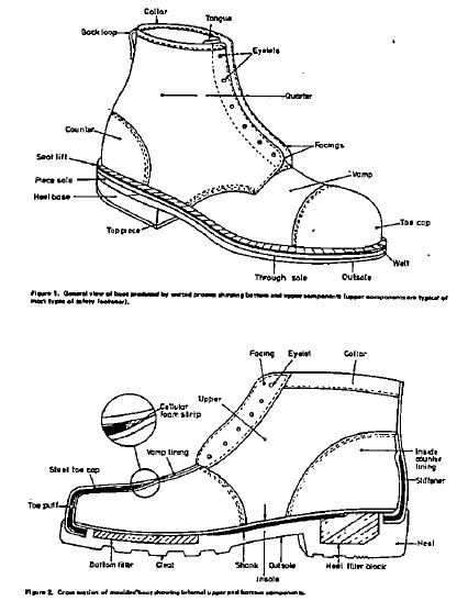
|
ZAMBIA BUREAU OF STANDARDS |
|
Zambian Standard ZS 189:1990 |
|
MAIZE MEAL (MEALIE MEAL) – Specifications |
|
1 SCOPE |
|
This Zambian Standard prescribes the requirements and methods of test for two types of maize meal, namely, Maize Breakfast Meal and Maize Roller Meal. |
|
2 DEFINITIONS |
|
For the purposes of this Standard the following definitions shall apply: |
|
2.1. Maize |
|
Zea mays and includes the maize endosperm and the germ. |
|
2.2. Maize breakfast meal |
|
The product obtained entirely from cleaned milling grades of maize at a minimum of 85% extraction rate. |
|
2.3. Maize roller meal |
|
The product obtained entirely from cleaned milling grades of maize at a minimum of 94% extraction rate. |
|
3 REQUIREMENTS |
|
3.1. Description |
|
Maize meal shall have a characteristic taste and smell free from rancidity, shall be free from fungal infestation, rodent contamination, dirt and other extraneous matter. |
|
3.2. Chemical Requirements |
|
Maize meal shall comply with the requirements specified in Table 1. |
|
4 PACKAGING AND MARKING |
|
4.1. Packaging |
|
Maize meal shall be packed in bags made of paper, rayon, polythene or hessian, protected from dust and moisture. |
|
4.2. Marking |
|
The labeling requirements of ZS 033: Part 1, in addition to the following information shall be shown on the label: |
|
TABLE 1. Requirements for Maize Meal |
||
|
Characteristic |
Requirements |
|
|
|
Maize breakfast meal |
Maize roller meal |
|
Moisture content, % max |
14.5 |
14.5 |
|
Protein content, % min |
5.0 |
5.0 |
|
Crude fibre, % max |
1.5 |
2.5 |
|
Crude oil, % max |
2.5 |
4.5 |
|
Free fatty acid, % max |
5.0 |
5.0 |
|
Total ash, % max |
1.0 |
2.0 |
|
Acid insoluble ash, % max |
0.2 |
0.2 |
|
Alcoholic acidity (as H2SO4) |
0.1 |
0.1 |
|
Colour grade No., max. |
5.5 |
10.0 |
|
Granularity, through 32 W (750U), % max |
90 |
80 |
|
(a) the name of the food; breakfast or roller meal whichever is applicable; |
|
(b) the branch name or trade mark; |
|
(c) the name and business address of manufacturer, parker of vendor; |
|
(d) the batch or code number; |
|
(e) the net mass; |
|
(f) the date of manufacture; and |
|
(g) the product may also be marked with the ZS Mark. |
|
NOTE: The use of the ZS Mark is governed by the Certification Mark Regulations. Information about the use of the mark may be obtained from the Zambia Bureau of Standards. |
|
5. Sampling |
|
Representative samples shall be drawn according to the methods prescribed in Annex A. |
|
6. Tests |
|
Tests shall be carried out in accordance with the methods prescribed in Annexes B to M. |
|
ANNEX A |
|
METHODS OF SAMPLING |
|
A.1 General Sampling Procedures |
|
A.1.1 Samples shall be drawn in a protected place not exposed to damp air, dust or soot. |
|
A.1.2 The sampling instrument shall be clean and dry when used. |
|
A.1.3 The samples, the material being sampled, the sampling instrument and the containers for the samples shall be protected from adventitious contamination. |
|
A.1.4 The samples shall be placed in clean and dry containers made of glass or polythene and of such size that they are almost completely filled by the sample. |
|
A.1.5 Each container shall be sealed airtight alter filling and marked with the following information: |
|
(a) the description of the sample; |
|
(b) the date of sampling; |
|
(c) the name and designation of samples; |
|
(d) the batch or code number; |
|
(e) the name of manufacturer; and |
|
(f) any other relevant particulars of the consignment or lot sampled. |
|
A.1.6 Samples shall be stored in a cool, dry place so that the temperature of the material does not vary unduly from the normal temperature. |
|
A.1.7 Sampling shall be done by a sampler acceptable to the purchaser and the vendor and shall be done in the presence of the purchaser the purchaser’s representative and the vendor or the vendor’s representative. |
|
A.2 SCALE OF SAMPLING |
|
A.2.1 Lot |
|
All the bags in a single consignment of the material drawn from a single batch of manufacture shall constitute a lot. If the consignment consists of different batches of manufacture, the batches shall be marked separately and the bags belonging to each batch shall constitute one separate lot. |
|
A.2.2 Gross sample |
|
A certain number of bags shall be selected for the purpose of sampling at random from a lot. The number of bags selected for sampling from lots of varying sizes shall be as here under indicated. |
|
TABLE 2. Sample Sizes |
|
|
Lot size (No. of bags) |
Sample size (Minimum No. of bags) |
|
2 to 8 |
2 |
|
9 to 27 |
3 |
|
28 to 64 |
4 |
|
65 to 125 |
5 |
|
126 to 216 |
6 |
|
217 to 343 |
7 |
|
344 to 512 |
8 |
|
513 to 729 |
9 |
|
730 to 1000 |
10 |
|
A.3 TEST SAMPLE AND REFEREE SAMPLE |
|
A.3.1 Preparation |
|
Using a suitable sampling instrument draw from the top, middle and bottom part of each bag in the gross sample about 0. 75 kg of the material and mix thoroughly to prepare a representative sample of that bag. |
|
A.3.2 Test sample |
|
Transfer a portion of the sample from each representative sample of a quantity being not less than 0. 25 kg into three separate sample containers. Seal the containers air-tight and label them with the particulars mentioned in A.1.5. A set of each sample containers from each bag sampled shall constitute the test sample. |
|
A.3.3 Referee sample |
|
One test sample shall be given to the purchaser and the second test sample shall be given to the vendor. The third test sample bearing the seals of the purchaser and the vendor shall constitute the referee sample, to be used in case of dispute. The referee sample shall be kept at a place agreed upon by the purchaser and the vendor. |
|
ANNEX B |
|
TEST FOR ACCEPTANCE |
|
B.1 Examination and Tests |
|
A purchaser may examine and test each of the portions constituting the test sample separately for compliance with the requirements of this standard or the purchaser prepare a composite sample representative of the whole lot by mixing all the portions constituting the test sample and the test composite sample. |
|
B.2 Criterion for Judgment |
|
When the individual portions in a test sample are separately examined and the results vary from one reduced sample to another the criterion for judging the lot for the purpose of acceptance on the basis of the results obtained shall be at the discretion of the purchaser, unless otherwise previously agreed between the purchaser and the vendor. |
|
ANNEX C |
|
Drying of Tests Samples |
|
Weigh accurately the amount of material required in a suitable moisture dish, previously dried in an electric oven and weighed. Place the dish in an electric oven maintained at 105 + 1°C for five hours. Cool the dish in a desiccator and weigh with the lid on. Repeat the process of heating, cooling and weighing at half-hour intervals until the loss in mass between two successive weighings is less than 1 mg. Record the lowest mass obtained. Preserve the dish containing this dried material in a desiccator, until required. |
|
ANNEX D |
|
DETERMINATION OF MAIZE |
|
D.1 Reagent |
|
Anhydrous ether. Wash commercial ethyl ether with three portions of water, add solid potassium hydroxide and let stand until most of the water is abstracted from ether. Decant the ether into a dry bottle and add small clean pieces of metallic sodium. Let stand until evolution of hydrogen ceases. Insert stopper and preserve the anhydrous ether over metallic sodium. |
|
D.2 Procedure |
|
Weigh accurately 2 g of sample dried as described in annex C and transfer to an extraction thimble. Extract using the anhydrous ether in a Soxhlet extraction apparatus. Adjust the heating to provide a condensation rate of 5 – 6 drops per second and extract for 4 hours. Transfer the ether extract to a weighed evaporating dish, evaporate the ether over a water bath and dry the residue at 100°C for 30 minutes. The difference in mass represents maize oil. Report the results as a percentage of the sample. |
|
ANNEX E |
|
DETERMINATION OF CRUDE FIBRE |
|
E.1 Reagent |
|
E.1.1 Dilute sulphuric acid, 1.25% m/v, prepared from analar sulphuric acid. |
|
E.1.2 Sodium hydroxide solution. 1.25%m/v, prepared from analar sodium hydroxide pellets. |
|
E.1.3 Prepared asbestos, spread asbestos, acid washed, medium fibre, on an evaporating dish and heat in a furnace for 16 hours at a temperature of 600°C. Remove from furnace, cool and boil with dilute sulphuric acid for 30 minutes, filter, wash once with dilute sulphuric acid and wash thoroughly with water. Dry and ignite for 2 hours at 600°C. Store in glass-stoppered containers. |
|
E.2 Procedure |
|
Weigh accurately about 2 g of well-mixed sample into an extraction thimble and extract using anhydrous ether (see D) in a Soxhlet apparatus for 2 hours. Transfer sample to a litre flask using a brush, add 1 g of prepared asbestos and 200 ml of boiling dilute sulphuric acid. Connect to reflux condenser and boil for 30 minutes. Rotate the flask and filter under suction using a 200 mesh stainless steel screen easily washed of digested residue. |
|
Wash with 75 ml boiling water. Drain filter, dry and transfer to the flask using 200 ml boiling sodium hydroxide solution. Boil for 30 minutes and filter as before. Wash with 25 ml boiling dilute sulphuric acid, followed by three 50 ml portions of boiling water and finally with 25 ml of methanol. Transfer the residue to a porcelain ashing dish by blowing back through filter. Dry the dish for 2 hours at 130 + 2°C. Cool in a desiccator and weigh. Ignite the dish at 600°C + 20°C for 30 minutes and re-weigh. Report difference in mass as crude fibre per cent. |
|
ANNEX F |
|
DETERMINATION OF TOTAL ASH CONTENT |
|
Weigh accurately about 3 g of a well-mixed sample in a porcelain dish that has been ignited, cooled in a desiccator and weighed soon after reaching room temperature. Ignite the sample in the dish over a small flame for an hour, transfer the dish to a muffle furnace and ignite at 550°C until light grey ash results. Cool in a desiccator and weigh soon after it reaches room temperature. Report the difference in mass as total ash; preserve the ash for determination of acid insoluble ash. |
|
ANNEX G |
|
DETERMINATION OF ACID INSOLUBLE ASH |
|
G.1 Reagent |
|
Dilute hydrochloric acid, 5N, approximately, prepared from Analar hydrochloric acid. |
|
G.2 Procedure |
|
Dissolve the ash obtained in Annex F in 25 ml of dilute hydrochloric acid, cover the porcelain dish with a watch glass and heat on a water bath for two minutes. Allow to cool and filter the contents of the dish through Whatman filter paper No. 42. Wash the filter with water until washings are free from acid. Return the filter paper and residue to the dish, incinerate over a small flame and remove the dish to a muffle furnace. Ignite at 600°C for 1 hour. Cool the dish in a desiccator and weigh. Repeat the heating, cooling and weighing at half hour intervals until the difference between two successive weighings is less than 1 mg. Report the results as percentage of the original sample. |
|
ANNEX H |
|
DETERMINATION OF ALCOHOLIC ACIDITY |
|
Weigh accurately about 10g of a well mixed sample, add to 100 ml of neutral 90% ethanol and allow to stand for 24 hours with occasional shaking, then titrate 50 ml of the supernatant liquid with 0. 05 M alcoholic sodium hydroxide solution to phenolphthalein. The acidity of the alcohol extract is calculated as sulphuric acid (H2SO4). |
|
ANNEX I |
|
DETERMINATION OF MOISTURE CONTENT |
|
Weigh accurately about 2 g of a well-mixed sample in a covered metal dish, previously heated to 130 + 3°C and weighed. Dry the dish and contents and the cover in an oven providing for ventilation at a temperature of 130 + 3 °C for 1 hour. The 1 hour period is to be counted from the time the oven reaches the temperature of 130°C. Cover the dish while still in the oven and transfer to a desiccator, containing re-ignited calcium oxide as drying agent. Weigh the dish and cover soon after it reaches room temperature. The loss in mass is reported as moisture per cent. |
|
ANNEX J |
|
DETERMINATION OF CRUDE PROTEIN |
|
J.1 Reagent |
|
All reagents shall be of analytical reagent quality and the water used shall be distilled water, or water of equal purity. |
|
J.1.1 Sulphuric acid (Concentrated) |
|
J.1.2 Sodium hydroxide (Concentrated) |
|
J.1.3 Indicator solution. Dissolve 0. 2 g each of methyl red and methylene blue indicators in a little water in a 500 ml volumetric flask and make up to the mark. |
|
J.l.4 Sodium hydroxide solution, 0.1 N or sulphuric acid, 0.1 N standardised. |
|
J.1.5 Boric acid solution, 4 % m/v |
|
J.1.6 Receiver solution, dilute 8 ml of methyl red/methylene blue mixed indicator solution with a litre of 4 % boric acid. |
|
J.1.7 Selenium, Kjeldahl catalyst tablets. |
|
J.2 Procedure |
|
Weigh accurately about 1 g of a finely ground sample and transfer to a 500 ml Kjeldahl flask containing 5 tablets of the selenium catalyst (or 8 g if it is in powder form) and 20 ml of concentrated sulphuric acid. Mix the contents of the flask, heat gently, until frothing has ceased, boil gently until the liquid is clear and then boil for 1.5 hours taking care that the flask is not directly heated above the level of the contents. |
|
When the digest is cool, add 150 ml of water, mix and add a few drops of antifoaming agent and 70 ml of concentrated sodium hydroxide poured down the side of the flask to form a bottom layer. |
|
Connect the flask to a condenser, with tight-fitting rubber stopper, the tip of which is immersed in 50 ml of receiver solution (K.1.6) contained in a 250 ml conical flask. Gently rotate the Kjeldahl flask to mix its contents thoroughly. Boil until all the ammonia has distilled (check with red litmus paper). Lower the conical flask to bring the tip of the condenser above the receiver solution and rinse the outside of the tip with water. Repeat the whole procedure with 5 ml of water in place of the sample for a blank determination. |
|
Titrate the sample and blank distillates to the same end point with standardised sodium hydroxide solution or standardized sulphuric acid solution. Subtract the sample titration from the blank titration to obtain the volume of standardised sodium hydroxide or sulphuric acid solution equivalent to the total nitrogen in the mass of sample taken. [1 ml of 0.1 N sodium hydroxide or sulphuric acid solution is equal to 0.0014 g of nitrogen] To obtain the percentage by mass of protein in the sample, multiply the percentage of total nitrogen by 6. 25. |
|
ANNEX K |
|
DETERMINATION OF FREE FATTY ACID |
|
K.1 Reagents |
|
K.1.1 Petroleum ether, (BP 40 – 60°C)3. |
|
K.1.2 Phenophthalein indicator, 5 g/m in methanol 50 % v/v. |
|
K.1.3 Sodium hydroxide, 0.1N standard volumetric solution. |
|
K.1.4 Ether or ethanol solution, 50: 50. Mix 225 ml diethyl ether, 225 ml methylated spirit and 50 ml of phenolphthalein indicator. |
|
K.2 Procedure |
|
Weigh accurately a dry and clean extraction flask. Weigh accurately 5 g of a thoroughly dried and finely ground sample and transfer into the extraction flask. |
|
Extract the oil with about 50 ml petroleum ether, contained in the flask which is now attached to a tube fitted with a cooling system. |
|
Detach the flask after 4 hours and dry off the excess solvent. Place the flask in an oven at 100°C to remove any moisture for 10 minutes, cool the flask in a desiccator and weigh the flask again. Dissolve the oil in about 2.5 ml 50:50 ether/ ethanol solution. Warm the contents a little and shake the flask, titrate with 0.1 N sodium hydroxide solution, to a faint pink colour. |
|
The end point of the titration is reached when the addition of a single drop produces a slight but definite colour change persisting for at least 15 seconds. |
|
K.3 Calculation |
|
The acidity expressed as percentage by mass of oleic acid, is given by the formula: 28. 2 (VN/m) |
|
Where: |
|
V is the volume in millilitres of sodium hydroxide solution; |
|
N is the normality of the sodium hydroxide solution; and |
|
m is the mass, in grams, of the test sample. |
|
ANNEX L |
|
DETERMINATION OF COLOUR GRADER NUMBER |
|
L.1 Apparatus |
|
L.1.1 Kent Jones apparatus |
|
L.1.2 Stop clock |
|
L.2 Procedure |
|
Weigh 30 g of sample into 250 ml beaker and add 50 ml of distilled water. Start the clock and mixing simultaneously. The mixing is done for 45 seconds only to achieve a smooth paste, which is then poured into a dead cell held at an angle of 45°. Place the cell in the holder and clamp in position. Check the zero at this point by pressing the Galvanometer key and make sure there is no movement of the spot. The cell holder is now lowered and the Galvanometer key control is pressed. The spot is returned to zero using the large control still holding the Galvanometer key down. This will have moved the circular scale from the working reference that it was set at to set zero. The reading on this scale is now the colour grade result in K.J.M. units. From the end of mixing to the point where the reading is taken should be 45 seconds making 90 seconds total. This timing is very important. |
|
ANNEX M |
|
SIEVING TEST (GRANULARITY) |
|
Weigh 100 g of the material and transfer to a laboratory sifter with a sieve of appropriate aperture size for 4 minutes. Brush the upper surface of the sieve and sieve again for 1 minute. Weigh the tails on the sieve, and report the result as percentage by mass. |
SECOND SCHEDULE
[Paragraph 3]
|
1. |
ZS 058 |
Laundry soap |
|
2. |
ZS 723 |
Peanut butter |
|
3. |
ZS 073 |
Industrial protective and safety footwear |
|
4. |
ZS 189 |
Maize meal (mealie meal) |
STANDARDS (COMPULSORY STANDARDS) (DECLARATION) ORDER, 2011
[Section 7]
Arrangement of Paragraphs
Paragraph
1. Title
2. Declaration of compulsory standards
3. Application of standards
SI 32 of 2011.
This Order may be cited as the Standards (Compulsory Standards) (Declaration) Order.
2. Declaration of compulsory standards
The Standards set out in the First Schedule are hereby declared as compulsory standards.
The Standards set out in the First Schedule shall apply to the respective commodities listed in the Second Schedule.
FIRST SCHEDULE
[Paragraph 2]
COMPULSORY STANDARDS
ZAMBIA BUREAU OF STANDARDS
ZS 547 Part I:2011
LUBRICATING OILS – SPECIFICATION
PART I
AUTOMOTIVE GEAR OILS
1. Scope
1.1 This Zambian Standard specifies requirements for automotive and manual transmissions, transaxles and axles operating under a variety of conditions of speed, load and gear types.
1.2 The automotive gear oil acceptance criteria, in terms of quality and performance level, shall be primarily based on the AP1 service designation. These are based on the type of service in which the gear oil will be used.
2. Note
AGMA American Gear Manufacturer’s Association
API American Petroleum Institute
ASTM American Society for Testing and Materials
CP centi Poise
COC Cleveland Open Cup
CSt centi Stokes
SAE Society of Automotive Engineers
ZS Zambian Standards
3. Normative reference
In this Standard, reference has been made to the following standards:
ASTM D92/IP 36 Test method for flash and fire points by Cleveland Open Cup (COC)
ASTM D130/IP 154 Test method for detection of copper corrosion from petroleum products by the copper strip test.
ASTM D2270/IP 226 Standard practice for calculating viscosity index from kinematic viscosity at 40ºc and 100 ºc.
ASTD 2983 Test method for low-temperature viscosity of automatic fluid lubricants measured by the Brook Field Viscometer.
ASTM D97/IP 15 Pour point method
ZS 317 Road tank vehicles for petroleum based flammable liquids-specification.
ZS 385 The Petroleum Industry: Part 1 – Storage and distribution of petroleum products in above ground bulk installations –Code of Practice.
ZS 396 Sampling petroleum products: Part 1 – manual sampling of liquid hydrocarbons.
4. Definitions
For the purpose of this Standard, the following definitions apply:
4.1 Additive
A compound added to engine oil to enhance properties and performance.
4.2 ASTM method
The test method published by the American Society for Testing and Materials, in the United States of America.
4.3 ASTM reference sequence
The reference test sequence given in STP 315H, published by the American Society for Testing and Materials in the United States of America.
4.4 Automotive
Equipment associated with self-propelled machinery usually vehicles driven by internal combustion engines.
4.5 Base oils
Refined additive-free oils of varying viscosity grades, which are used in the manufacture of formulated lubricants.
4.6 Category
A designation such as API GL-1 or API GL-5 for a given level of performance in specific filed tests.
4.7 Classifications
The systematic arrangement into categories according to different levels of performance in specified field tests.
4.8 Gear oil
A liquid that reduces friction and wear between the moving parts within a power transmission system, serves as a coolant and may contains additives to enhance its performance and inhibit rusting, oxidation and foaming.
4.9 IP Method
The test method published by the Institute of Petroleum in the United Kingdom.
4.10 SAE service classification
The internal combustion engine service classification as defined in SAE JI83, published by the Society of Automotive Engineers in the United States of America.
5. Requirements
5.1 General
5.1.1 The API service categories based on an open-ended alphanumeric gear lubricant designations (API GL1, API GL2, API GL3, API GL4 and API GL5) shall apply.
5.1.2 A marketer of automotive gear oil marketed in Zambia shall ensure that the automobile gear oil has a product data sheet which, apart from other proprietary information, shows all the details listed in Table 1 and 2 together with the corresponding properties.
6. Packaging and marking
6.1 Packaging
The condition of selling or transporting oil containers shall be such as not to be detrimental to the quality of the oil during normal storage or transportation and shall comply with the provisions and requirements of the following standards:
ZS 371 Road tank vehicles for petroleum based flammable liquids – specification.
ZS 385 The Petroleum Industry: Part I storage and distribution of petroleum products in above ground installations – Code of Practice.
Marking
The following information shall appear in legible and indelible marking on an automotive gear oil containers apart from other proprietary information:
(a) product brand name;
(b) manufacturer’s name;
(c) SAE Viscosity grade;
(d) API service category;
(e) Intended application;
(f) Quantity contained in litres or kilogrammes as applicable; and
(g) Safety, health and environmental information.
7. Sampling
Sampling shall be done in accordance with the provisions given in ZS 396 and ASTM D4057.
Table 1: Requirements for automotive API GL-4 gear oils
|
SAE Viscosity Grade |
SAE Grade |
75W |
80W |
75W/90 |
80W/90 |
90 |
85W/140 |
140 |
|
Product Identity |
Not applicable |
Brand |
Brand Name |
Brand Name |
Brand Name |
Brand Name |
Brand Name |
Brand Name |
|
Viscosity at 100ºC |
ASTM D445/I71 |
4.1 Min |
7.0 Min |
13.5 Min |
13.5 Min |
13.5-24.0 |
13.5-24.0 |
24.0-41.0 |
|
Viscosity |
ASTM |
90 Min |
90 Min |
90 Min |
90 Min |
90 Min |
90 Min |
90 Min |
|
Flash Point (COC), |
ASTM D92/IP36 |
144 Min |
190 Min |
178 Min |
200 Min |
200 Min |
200 Min |
200 Min |
|
Pour Point (ºC) |
ASTM D97/IP 15 |
-24 |
-24 |
-24 |
-24 |
-24 |
-24 |
-24 |
|
Copper Corrosion |
ASTM D130/IP |
2C Max |
2C Max |
2C Max |
2C Max |
2C Max |
2C Max |
2C Max |
Table 2: Requirements for automatic API GL-5 gear oils
|
TEST |
TEST METHOD |
REQUIREMENTS |
|
SAE Viscosity Grade |
SAE GRADE |
75W |
80W |
75W/90 |
80W/90 |
90 |
85W/140 |
140 |
|
Product Identity |
Not applicable |
Brand name |
Brand Name |
Brand Name |
Brand Name |
Brand Name |
Brand Name |
Brand Name |
|
Viscosity at |
ASTM D445/I71 |
4.1 Min |
7.0 Min |
13.5 Min |
13.5 Min |
13.5-24.0 |
24.0 |
24.0-41.0 |
|
Viscosity Index |
ASTM D2270/IP226 |
90 Min |
90 Min |
90 Min |
90 Min |
90 Min |
90 Min |
90 Min |
|
Flash Point (COC), ºC |
ASTM D92/IP36 |
200 Min |
200 Min |
200 Min |
200 Min |
184 Min |
200 Min |
200 Min |
|
Pour Point (ºC) |
ASTM D97/IP 15 |
-21 |
-21 |
-21 |
-21 |
-21 |
-21 |
-21 |
|
Viscosity of 150,000 |
ASTM D2983 |
-40 |
-26 |
-40 |
-26 |
– |
-26 |
– |
|
Copper Corrosion |
ASTM D130/IP 154 |
2C Max |
2C |
2C |
2C |
2C |
2C |
2C |
ZAMBIA BUREAU OF STANDARDS
ZS 547 Part 2: 2011
LUBRICATING OILS – SPECIFICATION
PART II
INDUSTRIAL GEAR OILS FOR OPEN GEARS
1. Scope
1.1 This Zambian Standard specifies requirements for open gear lubricants to be used for various methods of application to the general industrial helical, herringbone, spur and bevel open gears.
1.2 The open gear lubricants acceptance criteria shall primarily be based on the performance criteria stipulated by the American Gear Manufacturers Association. Reference will also be made to other institutions such as the International Organisation for Standard and the American Society for Testing and Material.
1.3 The industrial gear oil shall be a mineral oil blended with additives to provide the requisite level of oxidation and thermal stability, rust and wear protection, demulsibility and foam inhibition for application intended.
1.4 This Zambian Standard applies only to semi enclosed and open gearing systems, where associated bearings are lubricated separately.
2. Note
| AGMA | American Gear Manufacturer’s Association |
| API | American Petroleum Institute |
| ASTM | American Society for Testing and Materials |
| COC | Cleveland Open Cup |
| SAE | Society of Automotive Engineers |
| CSt | centi Stokes |
| CP | centi Poise |
| EP | Extreme Pressure |
| ISO | International Organisation for Standardisation |
| ISO VG | International Organisation for Standardisation |
| Viscosity grade | |
| PMCC | Pensky Martens Closed Cup |
3. Normative reference
In this Standard, reference has been made to the following standards:
|
ASTM D88 |
Test method for flash and fire points by Cleveland Open Cup (COC). |
|
ASSSTM D92/IP 36 |
Test method for flash and fire points by Cleveland Open Cup (COC). |
|
ASTM D93/IP 34 |
Test method for flash point of petroleum products by Pensky – Martens closed cup (PMCC). |
|
ASTM D130/IP 154 |
Test method for detection of copper corrosion form Petroleum Products by the copper strip tarnish test. |
|
ASTD D445/IP 71 |
Test method for Kinematic viscosity of transparent and opaque mineral oil in the presence of water. |
|
ASTM D892 |
Test method for forming characteristics of lubricating oils. |
|
ASTM D943 |
Test method for oxidation characteristics of inhibited mineral oils. |
|
ASTM D2270/IP 226 |
Practice for calculating viscosity index from kinematic viscosity at 40ºC to 100ºC. |
|
ASTM D2711 |
Test method for demulsibility characteristics of extreme pressure lubricating oils. |
|
ASTM D2893 |
Test method for oxidation characteristics of extreme pressure lubricating oils. |
|
ASTM D4057 |
Standard practice for manual sampling of petroleum and petroleum products. |
|
ZS 317 |
Road tank vehicles for petroleum based flammable liquids-specification. |
|
ZS 385 |
The Petroleum Industry: Part 1 – Storage and distribution of petroleum products in above ground bulk installations –Code of Practice. |
|
ZS 396 |
Sampling petroleum products: Part 1 – manual sampling of liquid hydrocarbons. |
4. Definitions
For the purpose of this Standard, the following definitions apply:
Additive
A compound added to engine oil to enhance properties and performance.
ASTM method
The test method published by the American Society for Testing and Materials, in the United States of America.
ASTM reference sequence
The reference test sequence given in STP 315H, published by the American Society for Testing and Materials in the United States of America.
Base oils
Refined additive-free oils of varying viscosity grades, which are used in the manufacture of formulated lubricants.
FZG
Foschungstelle fur Zahnrader und Getriebau (Research Institute for Gears and Gear Design, Germany).
Gear oil
A liquid that reduces friction and wear between the moving parts within a power transmission system, serves as a coolant and may contains additives to enhance its performance and inhibit rusting, oxidation and foaming.
AGMA Lubricant Number
Numbering as defined in AGMA 251.02, published by the American Gear Manufacturers Association.
R and O Gear Oils
Petroleum-based oils with rust and oxidation inhibitors (R and O).
4.9. EP Gear Oils
Gear oils that contain additives which prevent sliding metal surfaces from seizing under extreme pressure conditions.
4.10. IP method
The test method published by the Institute of Petroleum, United Kingdom.
5. Requirements
5.1 General
5.1.1 AGMA Lubricant based on an open-ended alphanumeric gear lubricant designations (AGMA ` to AGMA 13, inclusive for R and O Gear Oils and AGMA IEP to AGMA 13EP for EP Gear Oils) shall apply.
5.1.2 A marketer shall ensure that licensed open gear oils satisfied all bench testing performance requirements as stipulated in Table 1 to 4 of this standard and in selecting a particular lubricant, the user must take into account recommendations of the equipment manufacturer.
5.1.3 A manufacturer in the food and drug industry who uses lubricants recommended in this standard in food and drug industry applications shall ensure that accidental contact of the lubricant, with the products being manufactured in avoided.
5.2. Licensed Service Category
A marketer of open gear oil marketed in Zambia shall ensure that open oil has a product data sheet which, apart from other proprietary information, shows all the details in Tables 1, 2, 3 and 4 together with the corresponding properties.
6. Packaging and marking
6.1 Packaging
The condition of selling or transporting oil containers shall not be detrimental to the quality of the oil during normal storage or transportation and shall comply with the provisions and requirements of the following standards:
ZS 371 Road tank vehicles for petroleum based flammable liquids –specification.
ZS 385 The Petroleum Industry: Part I storage and distribution of petroleum products in above ground bulk installations –Code of Practice.
6.2 Marking
The following information shall appear in legible and indelible marking on an open gear oil containers apart from other proprietary information:
(a) product brand name;
(a) manufacturer’s name;
(b) ISO viscosity grade, or AGMA lubricant number or ASTM equivalent grade;
(c) Intended application;
(d) Quantity contained in litres or kilogrammes as applicable; and
(e) Safety, health and environmental information.
7. Sampling
Sampling shall be done in accordance with the provisions given in ZS 396 and ASTM D4057.
ZS 547 Part II:2011
Table 1 – AGMA Viscosity Grades for Open Gear Lubricants
|
AGMA Lubricant Number |
ASTM Equivalent Grade |
Corresponding ISO Viscosity |
Viscosity Ranges in cSt @ 37.8 Deg C |
|
|
R and O Gear Oils |
EP Gear Oils |
|
||
|
4 |
4EP |
S700 |
150 |
135 to 165 |
|
5 |
5 EP |
S1000 |
220 |
198 to 242 |
|
6 |
6 EP |
S1500 |
320 |
288 to 352 |
|
7 |
7 EP |
S2150 |
460 |
414 to 506 |
|
8 |
8 EP |
S3150 |
680 |
612 to 748 |
|
9 |
9 EP |
S7000 |
1500 |
1350 to 1650 |
|
10 |
10 EP |
S15000 |
– |
2880 to 3520 |
|
11 |
11 EP |
S21500 |
– |
4140 to 5060 |
|
12 |
12 EP |
S31500 |
– |
6120 to 7480 |
|
13 |
13 EP |
S15000 |
– |
25600 to 38400 |
Table 2 – Specification for R and O Gear Oils
|
Property |
Test Procedure |
Criteria for Acceptance |
|
Viscosity |
ASTM D 88 |
Must be as specified in Table 1 |
|
Viscosity Index |
ASTM D2270/IP/226 |
*90 min |
|
Oxidation stability |
ASTM D 94 number of |
Hours to reach a neutralisation |
|
|
2.0mg KOH |
|
|
|
|
AGMA Grade Hours (Mins |
|
|
|
1 and 21 500 |
|
|
|
3 and 4750 |
|
|
|
5, 6, 7, and 8500 |
|
Rust Protection |
ASTM D 665/IP/135 |
AGMA Lubricant Nos. 4 to 8 – no rust after 24 hours with synthetic sea water |
|
Corrosion Protection |
ASTM D 130/IP154 |
*#1 strip after 3 hours at 121 Deg ºC |
|
Foam Suspension |
ASTM D 892 |
*Must be within the limits specified in Table 4 |
|
Demulsibility |
ASTM D2711 |
*Must be within the limits specified in Table 4 |
|
Cleanliness |
None abrasives |
Must be free from grit and |
*Applicable to AGMA Lubricant Nos 4 to 8 only
Table 3 – Specification for EP Gear Oils
|
Property |
Test Procedure |
Criteria for Acceptance |
|
Viscosity |
ASTM D 88 |
Must be as specified in Table 1 |
|
Viscosity Index |
ASTM D2270/IP/226 |
*90 min |
|
Oxidation stability |
ASTM D 943 number of |
Hours to reach a neutralisation |
|
Rust Protection |
ASTM D 665/IP/135 |
AGMA Lubricant Nos. 4 to 8 – no rust after 24 hours with synthetic sea water |
|
Corrosion Protection |
ASTM D 130/IP154 |
*#1 strip after 3 hours at 121 Deg ºC |
|
Foam Suspension |
ASTM D 892 |
*Must be within the limits specified in Table 4 |
|
Demulsibility |
ASTM D2711 |
*Must be within the limits specified in Table 4 |
|
Cleanliness |
None abrasives |
Must be free from grit and |
|
|
|
|
|
|
|
|
|
|
|
|
|
Property |
Test Procedure |
Criteria for Acceptance |
|
Viscosity |
ASTM D 88 |
Must be as specified in Table 1 |
|
Viscosity Index |
ASTM D2270 |
*90 min |
|
Oxidation stability |
ASTM D 2893 |
*increase in Kinematic viscosity of oil sample @ 99 ºC degrees should not exceed 10 per cent. |
|
Rust Protection |
ASTM D 665 |
No rust after 24 hours with distilled water |
|
Corrosion Protection |
ASTM D 130 |
*#1 strip after 3 hours at 99 degrees(ºC) |
|
Foam Suspension |
ASTM D 892 |
*Must be within the limits specified in Table 4 |
|
Demulsibility |
ASTM D2711 |
*Must be within the limits specified in Table 4 |
|
EP Property |
Timken Test |
An oil which passes either a 20Kg Timken OK load or 9 stages on the FZG machine is considered acceptable. |
|
Additive Solubility |
None |
Must be filterable to 100 microns (wet or dry) without loss of EP additive |
*Applicable to AGMA Lubricant Nos. 4EP to 8EP only.
Table 4 – Test Procedure and Limits
|
1.0. Test Limits – ASTM D892 Foam Test |
|
|
|
|
|
|
Max Volume of Form (ml) After |
|
|
|
|
|
|
|
|
Temperature |
5 Minutes Blow |
10 Minutes Rest |
|
Sequence I |
24ºC |
75 |
10 |
|
Sequence II |
93ºC |
75 |
10 |
|
Sequence III |
24ºC |
75 |
10 |
|
2.0 Test Limits – ASTM D2711 Demulsibility |
|||
|
Max per cent water in the oil after 5-hour test |
0.50% |
||
|
Max cuff after centrifuging |
2.0 ml |
||
|
Min total free water collected during entire test |
30 ml |
||
|
3.0 Test Limits – ASTM D2711 Demulsibility Test (Modified for EP oils para 3.2.,ASTM D2711-69 |
|||
|
|
AGMA Grades |
||
|
|
|
|
|
|
Max per cent water in the oil after 5 – hour test |
2 EP to 6 EP |
7 EP to 8 EP |
|
|
Max cuff after centrifuging |
1.0 m% |
1.00% |
|
|
Min total free water collected during entire |
2.0 ml |
4.0 ml |
|
|
Test (Start with 90 ml of water) |
60 ml |
50 ml |
ZAMBIA BUREAU OF STANDARDS
ZS 547 Part III: 2011
LUBRICATING OILS – SPECIFICATION
Part III
INDUSTRIAL GEAR OILS FOR ENCLOSED GEARS
1. Scope
1.1 This Zambian Standard specifies requirements for mineral gear oils suitable for enclosed gear operating at various speeds and shock loadings.
1.2 The industrial gear oil shall be a mineral oil blended with additives to provide the requisite level of oxidation and thermal stability, rust and wear protection, demulsibility and foam inhibition for the intended application.
1.3 Industrial gear oil acceptance criteria in terms of quality and performance level shall primarily be based on the performance criteria stipulated by original equipment manufacturers such as David Brown and by institutions such as AGMA, ISO, Croft and US Steel.
2. NOTE
| AGMA | American Gear Manufacturer’s Association |
| API | American Petroleum Institute |
| ASTM | American Society for Testing and Materials |
| DIN | Deutsches Institute fur Normung (German Standards Institute) |
| SAE | Society of Automotive Engineers |
| API | American Petroleum Institute |
| ISO | International Organisation for Standardisation |
| SABS | South African Bureau of Standards |
| eSt | centi Stokes |
| mgKOH/g | milligrammes of potassium hydroxide per gramme of oil |
3. Normative references
In this Standard, reference has been made to the following standards:
|
ASTM D92/IP 36 |
Test method for flash and fire points by Cleveland Open Cup (COC) |
|
ASTM D445/IP 71 |
Test method for Kinetic viscosity of transparent and opaque liquids (the calculation of dynamic viscosity). |
|
ASTM D2270/IP 226 |
Practice for calculating viscosity index from kinematic viscosity at 40ºc and 100 ºc. |
|
ASTD D97/1P/15 |
Test method for pour of Petroleum Product. |
|
ASTM D 664 |
Total acid number of petroleum products by potentiometric titration. |
|
ASTM D665/IP 135 |
Test method for rust preventing characteristics of inhibited mineral oil in the presence of water. |
|
ASTM 943 |
Test method for oxidation characteristics of inhibited mineral oils |
|
ASTM D2270/IP 226 |
Practice for calculating viscosity index from Kinematic viscosity at 40ºc and 100 ºc. |
|
ASTM D 2893 |
Test method for oxidation characteristics of extreme pressure lubricating oils |
|
ASTM D4057 |
Standard practice for manual sampling of petroleum and petroleum products |
|
DIN 51354/IP334 |
Load carrying capacity test for oils – FZG Gear machine |
|
ZS 317 |
Road tank vehicles for petroleum based flammable liquids-specification. |
|
ZS 385 |
The Petroleum Industry: Part 1 – Storage and distribution of petroleum products in above ground bulk installations –Code of Practice. |
|
ZS 396 |
Sampling petroleum products: Part 1 – manual sampling of liquid hydrocarbons. |
4. Definitions
For the purpose of this Standard, the following definitions apply:
4.1 Additive
Material added to engine oil to enhance properties and performance.
4. 2 ASTM method
The test method published by the American Society for Testing and Materials.
4.3 ASTM reference sequence
The reference test sequence given in STP 315H, published by the American Society for Testing and Materials.
4.4 Base oils
Refined additive-free oils of varying viscosity grades, used in the manufacture of formulated lubricants.
4.5 Compound Gear Oil
Oil marked ‘Comp’ and compounded with 3% to 10% fatty or synthetic fatty oils.
4.6 Gear oil
A liquid that reduces friction and wear between the moving parts within a power transmission system, serves as a coolant and may contains additives to enhance its performance and inhibit rusting, oxidation and foaming.
4.7 Extreme Pressure Additive
Lubricant additive that prevents sliding metal surfaces from seizing under extreme pressure conditions.
4.7 FZG
Foschungstelle fur Zahnrader und Getriebau (Research Institute for Gear and Gear Design Germany).
4.9 IP Method
The test method published by the Institute of Petroleum in the United Kingdom
5. Requirements
5.1 General
5.1.1 Industrial Gear oils shall comply with the requirements detailed in Table 1 and Table 2.
5.1.2 An industrial gear oil shall not contain any lead additives.
5.1.3 A marketer shall ensure that all industrial gear oils marketed in Zambia has a product data sheet which, apart from other proprietary information, contains all the details listed in Table 1 and Table 2 together with the corresponding properties.
6. Packaging and marking
6.1 Packaging
The condition of selling or transporting oil containers shall be such as not to be detrimental to the quality of the oil during normal storage or transportation and shall comply with the provisions and requirements of the following standards:
ZS 371 Road tank vehicles for petroleum based flammable liquids –specification.
ZS 385 The Petroleum Industry: Part I storage and distribution of petroleum products in above ground bulk installations –Code of Practice.
6.2 Marking
All industrial gear oil containers shall bear apart from other proprietary information the following details.
(a) product brand name;
(b) manufacturer’s name;
(c) quantity contained in litres; and
(d) Safety, health and environmental information.
7. Sampling
Sampling shall be done in accordance with the provisions given in ZS 396 and ASTM D4057.
ZS 547 Part III: 2011
Table 1: Minimum requirements for EP industrial gear oil
|
TEST |
TEST METHOD |
REQUIREMENTS |
|||||||
|
ISO VG |
Not Applicable |
68 |
100 |
150 |
220 |
320 |
460 |
680 |
1000 |
|
AGMA |
Not Applicable |
2 EP |
3 EP |
4EP |
7EP |
7EP |
7EP |
8EP |
8AEP |
|
CROFT Designation |
Not Applicable |
B |
C |
D |
E |
F |
G |
– |
– |
|
David Brown Number |
Not Applicable |
2 |
3 |
4 |
5 |
6 |
7 |
8 |
9 |
|
Product Identity |
Not Applicable |
Brand name |
Brand name |
Brand name |
Brand name |
Brand name |
Brand name |
Brand name |
Brand name |
|
Viscosity at 40ºc, eST |
ASTM D445/IP 71 |
61.2-74.8 |
90-110 |
135-165 |
198-242 |
288-352 |
414-506 |
612-748 |
900-1100 |
|
Viscosity Index (min) |
ASTM D 2270/IP 226 |
90 |
90 |
90 |
90 |
90 |
90 |
90 |
90 |
|
Pour Point, ºc (Max) |
ASTM D97/IP 15 |
27 |
24 |
22 |
20 |
18 |
9 |
6 |
3 |
|
Flash Point (COC), ºc (min) |
ASTM (COC) ºC (min) |
200 |
200 |
200 |
200 |
200 |
200 |
200 |
200 |
|
Total Acid Number, KOH/g(max) |
ASTM D 664/IP 177 |
1.5 |
1.5 |
1.5 |
1.5 |
1.5 |
1.5 |
1.5 |
1.5mg |
|
FZG failure load stage (min) |
ASTM D 51354/IP 334 |
12 |
12 |
12 |
12 |
12 |
12 |
12 |
12 |
|
Rust Prevention |
ASTM D665/IP 135 |
Pass |
Pass |
Pass |
Pass |
Pass |
Pass |
Pass |
Pass |
|
Foaming characteristic Sequence I (max) |
ASTM D 892/IP 146 |
10/0 |
10/0 |
10/0 |
10/0 |
10/0 |
10/0 |
10/0 |
10/0 |
|
Sequence II (max) |
50/0 |
50/0 |
50/0 |
50/0 |
50/0 |
50/0 |
50/0 |
50/0 |
50/0 |
|
Sequence III (max) |
10/0 |
10/0 |
10/0 |
10/0 |
10/0 |
10/0 |
10/0 |
10/0 |
10/0 |
|
Oxidation |
ASTM |
Increase in Kinematic viscosity of oil sample at 95 ºC should not exceed stability D2893 10% |
Table 2: Minimum requirements for general industrial, gear oils-rust and oxidation oils
|
TEST |
TEST METHOD |
REQUIREMENTS |
|||||||
|
ISO VG |
Not Applicable |
68 |
100 |
150 |
220 |
320 |
460 |
680 |
1000 |
|
AGMA Designation |
Not Applicable |
2 |
3 |
4 |
5 |
6 |
7 COMP1 |
8 COMP1 |
8A COMP1 |
|
David Brown Number |
Not Applicable |
2M |
3M |
4M |
5M |
6M |
7M |
8M |
9M |
|
Product Identity |
Not Applicable |
Brand name |
Brand name |
Brand name |
Brand name |
Brand name |
Brand name |
Brand name |
Brand name |
|
Viscosity at 40ºc, eST |
ASTM D445/IP 71 |
61.2-74.8 |
90-110 |
135-165 |
198-242 |
288-352 |
414-506 |
612-748 |
900-1100 |
|
Viscosity Index (min) |
ASTM D 2270/IP 226 |
90 |
90 |
90 |
90 |
90 |
90 |
90 |
90 |
|
Pour Point, ºc (Max) |
ASTM D97/IP 15 |
27 |
24 |
22 |
20 |
18 |
9 |
6 |
3 |
|
Flash Point, ºc (min) (COC) |
ASTM D 92 IP 54 |
200 |
200 |
200 |
200 |
200 |
200 |
200 |
200 |
|
Total Acid Number, mgKOH/g (max) |
ASTM D 664/IP 177 |
1.5 |
1.5 |
1.5 |
1.5 |
1.5 |
1.5 |
1.5 |
1.5mg |
|
Foaming characteristic Sequence I (max) |
ASTM D 892/IP 146 |
10/0 |
10/0 |
10/0 |
10/0 |
10/0 |
10/0 |
10/0 |
10/0 |
|
Sequence II (max) |
50/0 |
50/0 |
50/0 |
50/0 |
50/0 |
50/0 |
50/0 |
50/0 |
50/0 |
|
Sequence III (max) |
10/0 |
10/0 |
10/0 |
10/0 |
10/0 |
10/0 |
10/0 |
10/0 |
10/0 |
|
Oxidation |
ASTM D2893 |
Increase in Kinematic viscosity of oil sample at 95 ºC should not exceed stability 10% stability |
|||||||
|
Oxidation stability |
ASTM D943 |
Hours to reach a neutralisation number of 2.0 |
Note: Oils marked ‘Comp’ are compounded with 3% to 10% fatty or synthetic fatty oils.
SECOND SCHEDULE
[Paragraph 3]
1.ZS 547 PART 1 Lubricating oils-automotive gear oils
2.ZS 547 PART 2 Lubricating oils-industrial gear oils for open gears
3.ZS 547 PART 3 Lubricating oils –industrial gear oils for enclosed gears.
STANDARDS (COMPULSORY STANDARDS) (DECLARATION) (NO. 1) ORDER
[Section 7]
Arrangement of Paragraphs
Paragraph
1. Title
2. Declaration of compulsory standards
3. Application of standards
SI 104 of 2011.
This Order may be cited as the Standards (Compulsory Standards) (Declaration) (No. 1) Order.
2. Declaration of compulsory standards
The Standards set out in the First Schedule are hereby declared as compulsory standards.
The Standards set out in the Second Schedule apply to the respective commodities listed therein.
FIRST SCHEDULE
[Paragraph 2]
COMPULSORY STANDARDS
ZAMBIA BUREAU OF STANDARDS
Zambian Standard ZS 201: 2011
EMULSION PAINTS FOR INTERIOR AND EXTERIOR USE—SPECIFICATION
1. SCOPE
1.1 This Zambian Standard covers the following types of paint:
(a) type 1 – suitable for exterior use; and
(b) type 2 – suitable for interior use.
1.2 Where the paint is meant for both interior and exterior use, it shall meet the requirements specified for both type 1 and type 2 paints.
2. REQUIREMENTS
2.1 Composition
The material of the paint shall consist of pigments and suitable extenders in suitable proportions, and in a medium consisting of a stable synthetic polymer dispersion in water with suitable ingredients as may be necessary to produce a material so as to satisfy the requirements of the Standard.
2.2 Condition of the Container
The paint on receipt in an unopened full container, which should be rust-free internally within the recommended shelf-life by the manufacturer, shall not have irritating or offensive odour and, if any separation of the liquid has taken place, the depth of the upper layer shall not exceed 5% of the total depth of the contents of the container. The paint shall be free from lumps and skins, shall not exhibit excessive settling, caking, granulation, levering or colour separation and shall be easily dispersed with a paddle to a smooth homogeneous state.
2.3 Volatile Content
The volatile matter content of the paint shall not be more than 50% (m/m).
2.4 Coarse Particles and Foreign Matter
The paint shall not leave a residue of more than 1% (m/m) on a sieve of nominal aperture size 75 lm.
2.5 Viscosity
The paint as supplied shall have a viscosity lying between 10 and 13 poises at 25 ± 0.5°C. As an alternative, the stormer viscometer can be used to determine the consistency which should be between 250 and 425 grams or 89 and 106 Krebs units at 25 ± 0.5°C.
2.6 Fineness of Grind
When tested in accordance with ZS 284, Part 18, the fineness of grind reading of the unthinned paint shall not exceed 20 lm.
2.7 Dilution Stability
When suitably thinned with water in accordance with the manufacturer’s instructions, for roller, brush or spray application, the material shall mix readily with a minimum amount of foaming to a smooth and homogeneous state. The foaming, if any, shall dissipate rapidly. After the well-mixed and reduced paint has been stored for seventy-two hours at 25 ± 5°C, it shall show no signs of instability of the emulsion. The paint shall readily re-mix to a smooth uniform state suitable for roller, brush or spray application.
2.8 pH Value
The pH value of the material when determined by a suitable glass electrode system shall be between 8.0 and 8.5.
2.9 Shelf-life
The paint, when stored at a temperature between 18°C and 30°C in shade and in fully sealed containers as delivered by the manufacturer, shall meet all the requirements of this Standard up to at least nine months from the indicated date of manufacture.
2.10 Temperature Stability
The paint when put into a 400 ml glass jar with ground-in cover, to about three quarters full, and kept fully closed in a suitable oven at a temperature of 40 ± 2°C for one month or 60 ± °C for forty-eight hours shall not develop an offensive odour and shall still comply with the requirements of 2.7, 2.13 and 2.14.
2.11 Mass in Kgs/Litre
The mass in kgs/litre of the material when tested in accordance with ZS 284, Part 17, shall not differ by more than + 5% from that of the approved sample.
2.12 Resistance to Alkali
The difference between the unsealed and the sealed material shall not be appreciable when examined visually.
2.13 Application
The material shall, after recommended thinning, be suitable for application by brush, spray or roller. The first coat shall work satisfactorily and during the application of the second coat, the paint shall brush, spray or work easily, flow, spread and join well. It shall show no floating, film coarseness or any other undesirable film characteristic in the wet or dry film.
2.14 Re-coating Properties
When three successive coats of paint, after suitable thinning with water, are applied under normal conditions on dry asbestos cement panel, at an interval of two hours between coats, by brushing, roller-coating or spraying at a spreading rate of approximately 12 square metres per litre, there shall be no lifting of the under-lying coats. The paint system shall not exhibit colour separation, sagging, pitting, flaking or cracking. No difficulty shall be experienced with the application of the successive coats by brushing, spraying or with the roller. The brush marks produced during brush application shall not be more pronounced than those on the first coat.
2.15 Drying Properties
Apply a coat of paint on a glass panel giving a wet film thickness of approximately 75 lm. The paint shall be surface dry at the end of twenty minutes and shall dry to a suitable condition for re-coating within two hours.
2.16 Specular Gloss at 85° (sheen)
Apply a coal of paint by means of a spreading device (e. g. doctor’s blade) on a glass panel.
2.16.1 giving a wet film thickness of approximately 75 lm.
2.16.2 The dry paint shall have the 85°C specular gloss given below, relevant to the type of finish specified by the manufacturer—
(a) flat finishes: 15 max; and
(b) egg-shell finishes: 16-50.
2.17 Colour
The colour of the paint specified shall be as agreed between the purchaser and vendor.
2.18 Reflectance of White Paints
White paint shall have a daylight 45°, 0° luminous directional reflectance relative to magnesium oxide of at least 85%.
2.19 Hiding Power
A paint that has the daylight 45°, 0° luminous directional reflectance value in column 1 of the Table below shall have the corresponding dry hiding power given in column 2.
|
TABLE: REQUIREMENTS FOR HIDING POWER |
|
|
Reflectance % |
Hiding Power, m2/l |
|
40 and more |
10 |
|
20-39.9 |
13.3 |
|
10 – 19.9 |
15.4 |
|
less than 10 |
10.0 |
2.20 Resistance to Wet Abrasion
For 1500 oscillations, the material shall be deemed to have passed the test if it does not show film defects like blistering, exposure of undercoat and finish and colour fading.
2.21 Resistance to Exterior Exposure
This test shall apply to type 1 paints. The paint shall not show more than a slight degree of dirt retention and shall show no sign of film breakdown, such as cracking, flaking or blistering after twelve months exposure.
2.22 Light Fastness
This test shall apply only to type 1 paints. Using a single carbon are apparatus and glass panels, the paint after one hundred and sixty-eight hours of exposure, shall not exhibit more than a slight change of colour.
2.23 Resistance to Staining
This test shall apply to both type 1 and type 2 paints. When tested, the paint film shall show no sign of staining.
2.24 Resistance to Development of Gloss
This test shall apply only to type 2 paints. Panels are prepared and aged. In the case of an egg-shell finish, the 85° specular gloss is measured. When the paint is tested, the 85° specular gloss (sheen) of flat finishes shall not increase by more than 50% over the original value.
2.25 Resistance to Fungal Growth
When the paint is specified as providing a fungus-resistant finish, the dry paint film both after forty-eight hours ageing and after six months ageing in standard air-drying conditions shall pass the test. This test applies to both type 1 and type 2 paints, except that for type 1 paints and for paints meant for both interior and exterior use, the test shall be carried out after six months’ exterior exposure instead of ageing for six months in standard air-drying conditions.
2.26 Water Drop Test
When an undiluted paint is applied to a glass panel to give a wet film thickness of about 120 lm and allowed to air-dry for twenty-four hours, no blistering, wrinkling, swelling or cracking of the paint film shall occur within a period of thirty minutes after 4 ml of distilled water in the form of circular drop is placed on the film.
ZAMBIA BUREAU OF STANDARDS
Zambia Standard ZS 295: 2011
HIGH GLOSS SYNTHETIC ENAMEL PAINT—SPECIFICATION
1. SCOPE
This Zambian Standard covers ready mixed high gloss synthetic resin based enamel paint for interior and exterior use as a finishing coat on metal, wood, sealed plaster walls and concrete surfaces, composition board and similar materials that have been primed or painted previously.
2. REQUIREMENTS
2.1 Viscosity
The viscosity of the paint at 25°C shall be between 70-75 Krebs units.
2.2 Application Properties
2.2.1 When tested with a lapping time of three minutes, the paint shall be judged to have good brushing properties if it can be applied, crossed, laid off and joined without difficulty.
2.2.2 It should also be able to be sprayed at a viscosity of twenty-eight to thirty seconds in a cup at 25°C when reduced with a suitable solvent as recommended by the manufacturer.
2.2.3 After the enamel has been reduced to spraying consistency and tested, there shall be no perceptible colour difference between the two dry surfaces.
2.3 Fineness of Grind
The fineness of grind reading for the unthinned paint shall not exceed 10 µm.
2.4 Drying Time
2.4.1 The drying time of a wet film of the unthinned paint produced by a standard 75 µm film applicator shall be as follows—
(a) surface dry ………………..not more than four hours; and
(b) hard dry ……………………not more than sixteen hours.
2.4.2 A pressure of 1 kg force shall be applied for the hard dry test.
2.5 Appearance
The paint when applied at a spreading rate of 10 m2/l to vertical surfaces shall be uniform and glossy with no evidence of runs, sags, brush marks, bloom, specks, flotation or other film defects.
2.6 Directional Reflectance for White Paint
The daylight 45°, 0°, luminous directional reflectance shall not be less than 85% relative to a freshly prepared surface of magnesium oxide. The application shall be by a suitable film applicator to produce a wet film of 60 to 65 µm per coat. The panels shall be aged for forty-eight hours at 25 ± 5°C and 60 ± 5% relative humidity before testing.
2.7 Gloss
2.7.1 The paint film, after drying for forty-eight hours at 25 ± 2°C and 60 ± 5% relative humidity, shall have specular reflection of not less than 80% (60° Head, glossmeter).
2.7.2 The same film after drying for seven days at 25 ± 5°C and 60 ± 5% relative humidity, shall have a specular reflection of not less than 80% (60° Head Glossmeter).
2.7.1 Retention of Gloss
The paint film shall have a specular reflection, after three months exposure, of not less than 70% (60° head glossmeter).
2.8. Yellowing of White Paint
2.8.1 When tested in accordance with the following method, the white paint shall show no yellowing after exposure in total darkness for a period of fourteen days and recovery for a period of seven days.
2.8.2 Apply two coats of the well mixed sample by brush at a spreading rate of 10 m2/l to the clean steel panels, of size 150 mm x 100 mm. Allow the panels to age for twenty-four hours in diffused daylight after application of the second coat at 25 ± 5°C and 60 ± 5% relative humidity. Place in a cupboard that excludes all light for a period of fourteen days. Do not open the cupboard during the testing period. At the end of this period, allow the panel to recover in diffused daylight then compare the test panels visually with a twenty-four hours old panel prepared in a similar manner.
2.9 Weathering
When tested for 1000, the paint film shall not—
(a) show chalking, checking or cracking;
(b) have a 60° specular gloss of less than 40; or
(c) have a colour change rating lower than the appropriate value given in Table 1.
|
TABLE 1: VISUAL COLOUR CHANGE RATING |
|
|
Colour |
Visual Colour Change Rating* min |
|
All colours, except yellow and orange |
6 |
|
Yellow and orange |
4 |
|
*Based on a figure of 10 for no defects |
2.10 Odour
The odour of the paint in the container and during and after application shall not be abnormally pungent, offensive or disagreeable.
2.11 Hiding Power
The wet hiding power of paints of the colours given in Table 2 using a morest chart, shall not be less than those specified in that Table.
Paints of other colours shall have wet hiding powers not less than the hiding powers of the colours they most nearly approximate in Table 2.
|
TABLE 2: HIDING POWER |
||
|
Colour |
Reflectance |
Minimum Wet Hiding Power |
|
White |
80 |
8.0 |
|
Black |
Nil |
25.0 |
|
Pastels – |
60 |
10.0 |
|
Light to medium colours – |
15-60 |
12.0 |
|
Dark colours – |
<<15 |
15.0 |
|
Yellow and orange – |
<<60 |
8.0 |
|
medium and dark |
<<60 |
10.0 |
|
Red |
<<30 |
7.0 |
|
Maroon |
<<5 |
5.0 |
|
Violet |
<<80 |
10.0 |
2.12 Storage Stability
2.12.1 The paint as supplied shall be free of any skin, dry sediment and coarse particles and shall show no evidence of livering or curdling or of other signs of container instability.
2.12.2 The paint shall be in such a condition that stirring readily produces a smooth uniform mixture of good brushing consistency within the viscosity limits.
2.12.3 The paint, when stored in the original sealed containers at temperatures between 15°C and 30°C, shall retain the properties detailed above for a period of not less than twelve months. The viscosity shall not increase by more than 10 Krebs units.
ZAMBIA BUREAU OF STANDARDS
Zambian Standard ZS 371: 2008
ROAD TANK VEHICLES FOR PETROLEUM-BASED FLAMMABLE LIQUIDS—SPECIFICATION
Introduction
This Standard covers road tank vehicles that are used predominantly for the transportation of petroleum based flammable liquids. It is assumed that discharge operations are carried out by the driver and take place using gravity or a pump. This Standard also makes provision for the commonly used type of road tank vehicle with compartments that are capable of transporting different types of petroleum products.
1. SCOPE
This Standard covers the requirements for tank vehicles intended for use on public roads, for transportation, at temperatures below their boiling point, of normally stable petroleum-based flammable liquids. Flammable liquids other than hydrocarbons are excluded from this Standard.
2. NORMATIVE REFERENCES
In this Standard, reference has been made to the following standards and legislation—
|
AISI |
– |
Steel products manual – stainless and heat-resisting steel; |
|
ASTM B209 |
– |
Standard specification for aluminium alloy, sheet and plate; |
|
BS 1470 |
– |
Specification for wrought aluminium and aluminium alloys for general engineering purposes – plate, sheet and strip; |
|
BS 1474 |
– |
Specification for wrought aluminium and aluminium alloys for general engineering purposes: bars, extruded round tubes and sections; |
|
BS 1490 |
– |
Specification for aluminium alloy ingots and castings for general engineering purposes; |
|
BS 5500 |
– |
Specification for unfired fusion welded pressure vessels; |
|
IEC 60529 |
– |
Degrees of protection provided by enclosures (IP Code); |
|
ISO 3874 |
– |
Series 1 Freight containers – handling and securing; |
|
ISO 7638 |
– |
Road vehicles – connectors for the electrical connection of towing and towed vehicles; |
|
SANS 141 |
– |
Glass-reinforced polyester (GRP) laminates; |
|
SANS 991 |
– |
Aluminium and alloy gravity die castings; |
|
SANS 1141 |
– |
Aircraft fuelling hose; |
|
SANS 1142 |
– |
Diesel engines modified for use in hazardous locations (other than in mines); |
|
SANS 1191 |
– |
High penetration – resistant laminated safety glass for vehicles; |
|
SANS 1207 |
– |
Motor vehicle safety standard specification for braking; |
|
SANS 1506 |
– |
Motor vehicle safety specification for braking; |
|
SANS 10123 |
– |
The control of undesirable static electricity; |
|
SANS 0228 |
– |
The identification and classification of dangerous substances and goods; |
|
SABS 10232 |
– |
Emergency information response system for road and rail; |
|
SANS 1518- 1 |
– |
Transportation of dangerous goods – Design requirements for road vehicles and portable tanks – Part 1 |
|
|
|
Requirements applicable to all vehicles; |
|
ZS 373 |
– |
Portable fire extinguishers; |
|
ZS 385-1 |
– |
The petroleum industry; |
|
Part 1 |
– |
Storage and distribution of petroleum products in above ground bulk installations – Code of Practice; |
|
ZS 385-2 |
– |
The petroleum industry |
|
Part 2 |
– |
Electrical installations in the distribution and marketing sector – Code of Practice; |
|
ZS 402 |
– |
The classification of hazardous locations and the selection of electrical apparatus for use in such locations; |
|
ZS437 |
– |
Pneumatic tyres – Specifications; |
|
ZS 675 |
– |
Road Vehicles – |
|
|
|
Road Speed Limiters – Guidelines; |
|
ZS 676 |
– |
Retro-reflective and fluorescent warning signs for road vehicles; |
|
ZS ISO 9001 |
– |
Quality management system – Requirements; |
|
|
|
The Energy Regulation Act (Cap. 436, Volume 24, Laws of Zambia); |
|
|
|
The Environmental Management Act, No. 12 of 2011; |
|
|
|
The Occupational Health and Safety Act, No. 36 of 2010; |
|
|
|
The Petroleum (Exploration and Production) Act, No. 10 of 2008; |
|
|
|
The Public Roads Act, No. 12 of 2002; |
|
|
|
The Road Traffic Act, No. 11 of 2002; and |
|
|
|
The Weights and Measures Act, Cap. 403 of the Laws of Zambia. |
NOTE:
All standards are subject to revision and since any reference to a standard is deemed to be a reference to the latest edition of that standard, parties to agreements based on this Standard are encouraged on currently valid national and international standards which may be obtained from the Zambia Bureau of Standards.
3. DEFINITIONS
For the purposes of this Standard, the following definitions apply—
3.1 Acceptable
Acceptable to the parties concluding the purchase contract, but in relation to the certification mark and to inspections carried out by the Zambia Bureau of Standards, acceptable to the Zambia Bureau of Standards.
3.2 Assize
To examine, verify or test an instrument to confirm it as an authorised measure.
3.3 Authorised Body
An organisation or person with acceptable qualifications, training and experience to carry out effective repair works on the road tank vehicle.
3.4 Auxiliary Engine
An engine that is additional to the main propulsion engine of the road tank.
3.5 Baffle
A non-liquid tight transverse or longitudinal partition in a tank.
3.6 Bulkhead
A liquid-tight transverse wall between adjacent compartments of a tank.
3.7 Calibration
A set of operations that establish, under specified conditions, the relationship between values of quantities indicated by a measuring instrument or measuring system, or values represented by a material measure or a reference material, and the corresponding values realised by standards.
3.8 Compartment
A liquid-tight division of a tank.
3.9 Compartment Tank
A tank that has two or more compartments, each of which has a total-volume capacity not exceeding 7,000 litres.
3.10 Demountable Tank
A tank that is designed to be lifted onto and mounted on a conventional truck that is to be used as a road tank vehicle.
NOTE:
A tank that is designed as a full load on rigid chassis, with attachment direct to the chassis in a positive and safe manner is not classified as a demountable tank for the purposes of this Standard.
3.11 Double Bulkhead
Two bulkheads that are placed in a tank next to each other, to divide the tank into two compartments.
3.12 Endurance Braking
A braking system intended to stabilise vehicle speed on a long descent, without the use of service, secondary or parking braking systems.
3.13 Explosion Protected
Descriptive of electrical apparatus that is designed and approved for use in for hazardous areas in accordance with one of the protection methods described in ZS 402 (or any acceptable equivalent).
3.14 Exposed Area
The area of the surface of a tank that is exposed to outside atmosphere direct.
3.15 Head
A liquid-tight transverse closure at the end of a tank.
3.16 Road Tank Vehicle
A tank truck, tank trailer, or truck-tractor and tank-semi-trailer combination.
3.17 Standard Reference Conditions
20°C and 101, 325 kPa absolute.
3.18 Tank
A container that has a liquid-full capacity in excess of 500 L, that is used for transporting petroleum-based flammable liquids and that is mounted permanently or temporarily on a vehicle other than for the purpose of supplying fuel for propulsion of the vehicle.
NOTE:
The term “tank” embraces the container and all components and ancillary equipment that affects its structural integrity.
3.19 Tank Semi-trailer
A vehicle with a tank mounted on it or built as an integral part of it, and so constructed that, when the semi-trailer is drawn by a truck tractor, through a fifth wheel connection, part of the load rests on the towing vehicle.
NOTE:
A tank semi-trailer, when coupled to a truck tractor, is an articulated vehicle.
3.20 Tank Trailer
A vehicle with a tank mounted on it or built as an integral part of it and so constructed that when the trailer is drawn by a motor vehicle, practically all its load rests on its own wheels.
3.21 Tank Truck
A single, self-propelled motor vehicle with a tank mounted on it.
3.22 Third Party
An independent body or person conducting an activity on behalf of another body
3.23 Type D Vehicle
A vehicle intended for the transportation of flammable, dangerous or sell reactive materials.
3.24 Ullage
That portion of the total-volume capacity of a tank that is not occupied by its liquid contents, expressed as a percentage of the total-volume capacity.
|
4. SYMBOLS AND ABBREVIATIONS |
||
|
ASTM |
– |
American Society for Testing and Materials; |
|
BS |
– |
British Standards; |
|
kPa |
– |
Kilopascal; |
|
IEC |
|
International Electro-technical Commission; |
|
IP |
– |
Degrees of protection provided by enclosures in accordance with IEC 60529; |
|
SANS |
– |
South African National Standards; |
|
Min |
– |
Minimum; and |
|
Kg/m3 |
– |
Kilograms per cubic metre. |
5. REQUIREMENTS
5.1 General Requirements
5.1.1 Road tank vehicles and their ancillary equipment shall comply with this Standard and all other relevant statutory requirements and regulations. The ancillary requirements on road tank vehicles, type D, shall include the items in Table 1.
|
TABLE 1: ANCILLARY REQUIREMENTS ON ROAD TANK VEHICLES |
||
|
Sub clause |
Requirement |
Vehicle Type D |
|
Electrical Equipment |
||
|
5.8.7.2 |
Wiring |
X |
|
5.8.7.3 |
Battery master switch |
X |
|
5.8.7.4 |
Batteries |
X |
|
5.8.7.5 |
Permanently energised circuits |
X |
|
5.8.7.6 |
Electrical installation at rear of drivers cabin |
X |
|
Braking Equipment |
||
|
5.9.1 |
General |
X |
|
5.9.2 |
Anti-lock braking system |
X |
|
5.9.3 |
Endurance braking system |
X |
|
Prevention of Fire Risks |
||
|
5.10.1 |
Vehicle cab |
X |
|
5.10.2 |
Fuel tanks |
X |
|
5.8.2 |
Engine |
X |
|
5.10.3 |
Exhaust system |
X |
|
5.10.4 |
Endurance braking |
X |
|
Combustion Heaters |
||
|
5.10.5.1 |
Heaters |
X |
|
5.10.3 |
Exhaust system |
X |
|
5.10.5.2 |
Operation |
X |
|
5.10.5.3 |
Switching |
X |
|
Recommended Equipments |
||
|
5.15 |
Speed limitation devices |
X |
|
|
Automatic speed and time recording devices |
O |
NOTE:
X – Mandatory requirement
O – Optional requirement
5.1.2 Tank compartments discharge valves shall be colour-tagged to identify product loaded and minimise the possibility of cross contamination. The international petroleum colour coding scheme shall apply as shown below—
|
Product |
Identification Colour Mark |
|
Leaded Petrol |
Orange |
|
Unleaded Petrol |
Green |
|
Diesel |
Straw |
|
Illuminating Kerosene (Paraffin) |
Blue |
|
Jet A-l |
Black |
5.2. Materials
5.2.1 Metals for Tanks
Tanks shall be constructed of an aluminium alloy, a low carbon steel, a high-strength low carbon steel, a high-strength low alloy steel, or a stainless steel as required. The metal shall be free from rust, scale, cracks, laminations and surface blemishes.
5.2.2 Aluminium Alloys
An aluminium alloy shall comply with requirements for—
(a) grade 5252 or 5083 of BS 1470 or grade 5454 of ASTM B209 or acceptable equivalent standards, in the case of sheets and plates;
(b) grade 6061, 6063 or 6082 of BS 1474 or equivalent and acceptable standard in the case of extrusions; and
(c) grade SA22 of SANS 991 or grade LM6 or LM18 of BS 1490 or equivalent and acceptable standards, in the case of castings.
5.2.2.1 Steel
A suitable low carbon or high-strength low alloy steel shall be of weldable quality and shall have physical properties at least equal to the appropriate minima given in Table 2.
|
TABLE 2: MINIMUM MECHANICAL PROPERTIES OF STEEL (OTHER THAN STAINLESS STEEL) |
||
|
Mechanical Property |
Low Carbon Steel |
High-strength Low Alloy Steel |
|
Yield stress, MPa, min |
172 |
310 |
|
Ultimate tensile strength MPa, min |
310 |
414 |
|
Elongation 5.65 |
20 |
25 |
|
Impact resistance at -20°C, J, min |
20 |
20 |
|
(1) Charpy V-notch |
|
5.2.2.2 Stainless Steel
A stainless steel shall comply with the requirements for one of the following grades of AISI steels (or acceptable equivalent):
304, 304L, 310, 316, 316L, 317, 317L, 321 or 347.
NOTE:
The attention of purchasers is drawn to the advisability of using (to avoid carbide precipitation) one of the low carbon grades or one of the stabilised grades.
5.2.3 Pipes, Fittings and other Ancillary Equipment
Materials for pipes, fittings, valves, manifolds, etc. shall be of a suitable material that is compatible with the material of the tank and with the flammable liquid that is to be transported in the tank.
5.2.4 Gasket Joint Rings and Other Components
Gasket joints and components designed to come into contact with the flammable liquid shall be of a suitable material that is compatible with the flammable liquid that is to be transported in the tank, preferably, cork and asbestos materials or an approved gasket material.
5.2.5 Other Materials
Components that do not come into contact with the flammable liquid may be of any material of adequate strength and that is acceptable for the required duty.
Note: Consideration should be given to the effects of galvanic corrosion when dissimilar metals (especially when one of these is aluminium or an aluminium alloy) are used in combination.
5.3 Tank Design
5.3.1 General
A tank and its ancillary equipment shall be designed in accordance with sound engineering principles, due consideration having been given to expected road conditions.
5.3.2 Capacity
5.3.2.1 The tank, which may be of the single-compartment or multi-compartment type, shall have a total-volume capacity, including a usage of between 2.5% and 5% of that capacity at 47°C of the liquid as required, and in no case shall the capacity of a compartment exceed 7,000 litres.
5.3.2.2 The maximum volumetric capacity shall not apply to heavy fuel oil. In addition, the total-volume capacity of a tank calculated on the liquid density of the product that is to be transported shall be such that when the road tank vehicle is fully loaded, its mass does not exceed the appropriate requirements of the Road Traffic Act, No. 11 of 2002 of the Laws of Zambia and the Public Roads Act, No. 12 of 2002 of the Laws of Zambia.
5.3.2.3 The volumetric quantity carried in the compartment shall be as calibrated by the Zambia Weights and Measures Agency and the usage mark sealed.
5.3.2.4 The Zambia Weights and Measures Agency shall conduct tank calibration and issue a certificate at least once a year or during the following instances—
(a) after the usage marks have been disturbed;
(b) after major repairs have been carried out on the tank;
(c) after vehicle combination changes;
(d) after any damage to the shell of the tank; or
(e) after any change of ownership.
5.3.2.5 The manhole covers shall be secured by four Zambia Weights and Measures seals, sealed diagonally for the bolted and hooked manhole types and one seal for the belted manhole type.
5.3.3 Shape
The tank may be of circular, elliptical or any other acceptable cross-section and shall be self-draining.
5.3.4 Maximum Stress Value
The maximum calculated stress value of a tank, including all stresses given in 5.3.5 to 5.3.7, shall not exceed 20% of the tensile strength of the material used for its construction.
5.3.5 Design Pressure
The design pressure shall be at least 23 kPa plus the pressure exerted by the static head of liquid in the fully loaded tank in the normal position. This shall be based on the greater of the density at 20°C of the flammable liquid for which the tank is being designed or 865kg/m3.
5.3.6 Dynamic Loading
Each tank and its components and ancillary equipment shall be designed to withstand dynamic loading in all directions and for all load configurations. The total dynamic loading shall be deduced by multiplying the static loads in question by the following acceleration factors considered individually—
(a) 2g in the direction of travel;
(b) 1g in the vertically upwards direction;
(c) 2g in the vertically downwards direction; and
(d) 1g in the transverse horizontal direction.
NOTE: For the safety factors in paragraphs (a) to (d) above, the safety devices discussed in 5.5 shall apply.
5.3.7 Additional Loads
The following additional loads shall be taken into account and, where applicable, a vector summation of all the loads under dynamic loading conditions shall be made—
(a) superimposed loads such as operating equipment, insulation, linings, hose tubes, cabinets and piping;
(b) reactions at supporting lugs and at saddles or other supports; and
(c) differential thermal expansion of dissimilar metals.
5.3.8 Distribution of Loads
The loads from supports shall be borne by bulkheads, baffles or ring stiffeners and shall be distributed as widely over the members as is practicable by using pads, gussets or other appropriate means of avoiding stress concentration.
5.3.9 Towing
For tank trailers the calculated D-value of the tow-eye and the tow-hitch shall always be less than that of the actual rating on the tow-eye. The tow-eye and the tow-hitch shall both be supplied by an approved supplier.
5.3.10 Shell, Meads, Bulkheads and Baffles
5.3.10.1 Thickness of the Shell, Heads, Bulkheads and Baffles
Thickness of the shell, the heads, and where fitted, the bulkheads and baffles shall be—
(a) such that, under dynamic loading conditions, the maximum stress value given in 5.3.4 is not exceeded; and
(b) not less than the relevant minimum given in Table 3 or 4 as appropriate and in no case, except at the knuckle-radius, shall the thickness of a tank head be less than the thickness of the shell.
NOTES:
1. The material thickness given in Tables 2 and 3 are based on a liquid density of 865 kg/m3. Where the liquid density of the flammable liquid to be conveyed in the tank exceeds 865 kg/m3, the thickness of the shell will have to be proportionally increased.
2. Where an aluminium alloy is used for the construction of a head, bulkhead, baffle or ring stiffener it shall be in the O (annealed) or stronger temper. A shell shall be constructed of material with properties at least equal to grade 5454 of ASTM B209 in the H32 or H34 tempers, or where lower tensile strength tempers are used, the minimum thickness of shell material given in Table 2 shall be proportional increased.
3. Consideration should be given to the loss of strength of an aluminium alloy in the welded condition (see 5.4.2.3).
5.3.10.2 Stiffening of Heads, Bulkheads and Baffles
Unless a proven equivalent form of stiffening is provided, the following requirement shall apply—
Heads, bulkheads and baffles for all tanks shall be dished to a depth, exclusive of any flange of at least 120 mm/m of the depth of the minor axis of the tank cross section.
|
TABLE 3: MINIMUM THICKNESS OF SHELL MATERIAL(1) |
||||||||||
|
Rated Capacity V l/m of Tank Length |
Maximum Shell Radium |
Maximum Thickness |
|
|
|
|
|
|
||
|
R |
L<<0.9m |
|
0.9m <<1<<1.4m |
|
1.4m<<1<<1.5m |
|
||||
|
|
M |
LCS |
SS HSLA |
AL |
LCS |
SS HSLA |
AL |
LCS |
SS HSLA |
AL |
|
V<< 1 400 |
1.8< |
2.0 |
1.6 |
2.2 2.2 |
2.0 |
1.6 |
2.2 |
2.0 2.4 |
1.8 |
2.4 |
|
|
2.3< |
2.0 |
1.6 |
2.4 |
2.0 |
1.8 |
2.4 |
2.8 |
2.0 |
2.8 |
|
|
3.2< |
2.0 |
1.8 |
2.8 |
2.4 |
2.0 |
2.8 |
3.0 |
2.4 |
3.0 |
|
|
|
2.4 |
2.0 |
|
2.8 |
2.4 |
3.0 |
|
2.8 |
3.8 |
|
|
1.8<<R |
2.0 |
1.6 |
2.2 |
2.0 |
1.8 |
2.4 |
2.4 |
2.0 |
2.8 |
|
|
1.8< |
2.0 |
1.8 |
2.4 |
2.4 |
2.0 |
2.8 |
2.8 |
2.4 |
3.0 |
|
1 400< |
2.3< |
2.4 |
2.0 |
2.8 |
2.8 |
2.4 |
3.0 |
3.0 |
2.8 |
3.8 |
|
|
3.2< |
2.8 |
2.4 |
3.0 |
3.0 |
2.8 |
3.8 |
3.5 |
3.0 |
4.4 |
|
|
1.8<<R |
2.0 |
1.8 |
2.4 |
2.4 |
2.0 |
2.8 |
2.8 |
2.4 |
3.0 |
|
|
1.8< |
2.4 |
2.0 |
2.8 |
2.8 |
2.4 |
3.0 |
3.0 |
2.8 |
3.8 |
|
2 100< |
2.3< |
2.8 |
2.4 |
3.0 |
3.0 |
2.8 |
3.8 |
3.5 |
3.0 |
4.4 |
|
|
3.2< |
3.0 |
2.8 |
3.8 |
3.5 |
3.0 |
4.4 |
4.0 |
3.5 |
5.0 |
|
|
1.8<<R |
2.4 |
2.0 |
2.8 |
2.8 |
2.4 |
3.0 |
3.0 |
2.8 |
3.8 |
|
|
1.8< |
2.8 |
2.4 |
3.0 |
3.0 |
2.8 |
3.8 |
3.5 |
3.0 |
4.4 |
|
V> 2 700 |
2.3< |
3.0 |
2.8 |
3.8 |
3.5 |
3.0 |
4.4 |
4.0 |
3.5 |
5.0 |
|
|
3.2< |
3.5 |
3.0 |
4.4 |
4.0 |
3.5 |
5.0 |
4.0 |
4.0 |
5.5 |
|
(1) The minimum thickness given in the Table can be less than those required in terms of 5.3.10.1(a). |
||||||||||
|
Legend— |
||||||||||
|
L indicates distance between heads, bulkheads, baffles or ring stiffeners |
||||||||||
|
LCS indicates low carbon steel |
||||||||||
|
SS indicates austenitic stainless steel |
||||||||||
|
HSLA indicates high-strength low alloy steel |
||||||||||
|
AL indicates aluminium alloy |
|
TABLE 4: MINIMUM THICKNESS OF HEADS (1), BULKHEADS AND BAFFLES |
|||
|
Rated Capacity V |
Minimum Thickness (mm) |
||
|
l/m of tank length |
LCS |
SS |
AL |
|
V<<1 400 |
2.0 |
1.8 |
2.4 |
|
1 400 < |
2.4 |
2.0 |
2.8 |
|
2 100< |
2.8 |
2.4 |
3.0 |
|
V>2 700 |
3.0 |
2.8 |
3.8 |
|
(1) The minimum thickness given in the Table can be less than those required of 5.3.10.1(a). |
|||
|
Legend— |
|||
|
L indicates distance between heads, bulkheads, baffles or ring stiffeners |
|||
|
LCS indicates low carbon steel |
|||
|
SS indicates austenitic stainless steel |
|||
|
HSLA indicates high-strength low alloy steel |
|||
|
AL indicates aluminium alloy |
5.3.11 Circumferential Reinforcement
5.3.11.1 Double bulkheads, where fitted, shall be separated by means of an air space that is vented and provided with drainage facilities.
5.3.11.2 Each ring stiffener shall be continuous around the circumference of the shell and where an air space is enclosed, the space shall be vented and provided with drainage facilities.
5.3.11.3 Baffles shall be adequately vented on the horizontal and vertical structure.
A ring stiffener shall have a section modulus about the neutral axis of the ring section parallel to the shell that is at least equal to the value calculated by the following formula—
I/C = KWL
Where—
I/C is the section modulus in cubic millimetres;
K is 0.0069 of low carbon, high-strength low alloy, and austenitic stainless steel and 0.01186 for aluminium alloys;
W is the width or diameter of the tank in millimetres; and
L is the ring spacing (distance from the midpoint of the unsupported shell on one side of the ring stiffener to the midpoint of the unsupported shell on the opposite side of the ring stiffener) in millimetres.
5.3.11.4 Where a ring stiffener is welded to the shell in accordance with 5.4.3 a portion of the shell maybe used as part of the ring section modulus. The portion of the shell used in this calculation shall not exceed the relevant maximum given in column 3 of Table 5.
|
TABLE 5: CIRCUMFERENTIAL RING STIFFENERS – SHELL SECTION CREDIT THAT MAY BE INCLUDED IN RING SECTION MODULUS |
||
|
Number of welds between ring stiffener and shell |
Distance between parallel ring stiffener to shell weld |
Shell section credit, max |
|
1 |
— |
20 d |
|
2 |
less than 20 d |
d + 20 d |
|
3 |
more than or equal to 20 d |
40 d |
|
Where – d is the shell thickness in millimetres |
5.4. Construction
5.4.1 General
All welding shall be carried out by a certified welder by means of an acceptable welding process and using a suitable filler metal. The welding procedure used shall be such as to ensure that the filler metal, the heat affected zone and the surrounding parent metal are free from cracks, unacceptable cavities and trapped slag, and when relevant, acceptable free from tungsten inclusions. Butt welds shall have complete penetration. Fillet welds shall have a leg length at least equal to the thickness of the thinner of the parts being joined.
NOTE:
The welding of aluminium alloys should be carried out in accordance with BS 3019-1 and BS 3571-1 (or equivalent standards).
5.4.2. Welding
5.4.2.1 Welds in Steel and Stainless Steel
The mechanical properties of welded joints shall be equal to at least 85% of (and the corrosion resistance at least equal to) the minimum specified for the parent metal.
5.4.2.2 Welds in Aluminium Alloys
When subjected to transverse tensile test, a weld joint in an aluminium alloy, with the reinforcement removed shall have a tensile strength of at least the relevant value given below.
5.4.2.3 In the case of a joint between two dissimilar alloys, the tensile strength shall be at least that of the alloy that has the lower tensile strength.
|
Alloy Designation |
Ultimate Tensile Strength |
|
5083 |
275 |
|
5251 |
160 |
|
5454 |
215 |
|
6061 |
165(1) |
|
6063 |
120(1) |
|
6082 |
165(1) |
(1) These values are for material welded in the TF condition after natural ageing for three days.
Where—
TF is the Temper Designation of Aluminium; and
F — As fabricated, applies to products in which no thermal treatments or strain-hardening methods are used to shape the product.
5.4.3 Baffle and Ring Stiffener Joints
A baffle (or baffle-attaching ring) or a ring stiffener used for tank reinforcement (see 5.3.11) shall be fully welded around the circumference of the tank.
5.4.4 Overturn Protection
Each closure for opening, including manhole, fill or inspection openings and each valve fitting, pressure relief device, vapour recovery stop valve or the filling retaining located within the upper two-thirds of a cargo tank circumference (or cross-section perimeter in the case of non-circular tanks) shall be protected by being enclosed inside the body of the tank or by being enclosed inside an overturn damage protection device or being 125% as strong as such damage protection device would be.
5.4.4.1 An overturn damage protection device on a road tank shall be designed and installed to withstand any load normal (perpendicular to the tank surface) or tangential (in any direction perpendicular to the normal load) to the tank shell, applied anywhere over the protected part of the tank and equal to at least twice the weight of the load tank vehicle. The design shall be based on the ultimate strength of the material used.
5.4.4.2 These design loads may be considered independently. If more than one overturn protection device is used, each device shall be capable of carrying its proportionate share of the applicable loads and in each case at least a quarter of the applicable total tangential load. The design shall by means of calculations, tests, or a combination of test and calculations be proven capable of carrying the applicable loads. Deformation of the damage protection device is acceptable provided that the devices being protected are not damaged.
5.4.4.3 An overturn damage protection device that would otherwise allow the accumulation of liquid on the top of the tank shall be provided with drain that directs the liquid to a safe point of discharge, away from any structural component of the road tank vehicle.
5.4.4.4 The overturn damage protection device shall be so constructed to at least 60 mm above the manhole covers.
5.4.5 Manholes and Fill Openings
Each tank compartment shall be provided with a manhole of diameter at least 400 mm, or with a 400 mm x 300 mm oval manhole. In the case of an oval manhole, the orientation shall be in line with the Weights and Measures Act, Cap. 403 of the Laws of Zambia. The manhole cover can be fitted with a hatch for opening and filling. The manhole cover and when relevant the hatch closure, shall not leak or fail when the tank is subjected to the test given in 7.2. The manhole shall always be in the centre.
5.5 Fitting and Attachments
5.5.1 General
All attachments to a tank shall be made from materials that are compatible with the material of the tank. The filling and discharge devices (including flanges and threaded plugs) and any protective caps shall be capable of being secured against unintended opening.
5.5.2 Valves
5.5.2.1 Design and Mounting
5.5.2.1.1 Each liquid discharge opening shall be provided with a spring-loaded valve that opens towards the tank interior and is of a type that, when de-energised, will close automatically (fail safe). The valve seat shall be located within the mounting pad and the valve stem shall not be attached to the actuator.
5.5.2.1.2 The valve assembly shall be of a design such that in the event of an accident, the actuator and the outlet pipe can break away, causing the valve to close automatically (fail safe). Alternatively, where the valves do not have a breakaway section, they shall be adequately protected by an under-rail damage protection device.
5.5.2.2 Controls
Valve actuators shall be operated by spring-loaded mechanical levers, hydraulic or pneumatic means, with controls designed to give rapid response. An additional spring loaded mechanical lever, hydraulic or pneumatic control (emergency trip) shall be situated in a position away from any discharge point, and an acceptable means of automatically closing the valve(s) in the event of a fire shall be provided.
5.5.3 Vents
Each tank compartment shall be provided with at least one pressure-and-vacuum vent that is so designed as to prevent loss of liquid through the vent owing to surge or to the vehicle’s overturning. The vent(s) shall be mounted, shielded and drained in such a manner as to prevent the accumulation of water. The exit of all vents other than emergency vents shall be covered with wire gauze of nominal aperture size in the range 425µm to 600µm. Each vent shall comply with the requirements given in 5.5.3.1 to 5.5.3.4.
5.5.3.1 Normal Vents
A normal vent shall have an unrestricted outlet area of at least 280mm2. When tested the vent shall start to open at a pressure not exceeding 7 kPa.
5.5.3.2 Filling and Discharging Vents
Where a tank compartment is designed for filling and discharging with the hatch closure closed, it shall be provided, where necessary, with an artificial vent at the specified liquid load and discharging rates for the tank (see 6.1), in addition to the venting provided in terms of 5.5.3.1.
5.5.3.3 Emergency Vents
5.5.3.3.1 The following requirements shall be complied with—
5.5.3.3.2 Each tank or compartment of a tank (as relevant) shall be provided with one or more emergency vents of total capacity determined in accordance with Table 6.
5.5.3.3.3 Pressure-actuated emergency vents shall be of a design that in the case of a pressure increase the vent(s) will function in any overturn attitude of the vehicle. Each such vent shall open at a pressure between 23.5 kPa and 25.0 kPa and close as soon as the pressure drops below this value and shall have a flow rate corrected to standard reference conditions of at least 170 m3 of free air per hour.
5.5.3.3.4 Where the pressure-actuated emergency vent(s) cannot provide the total minimum venting capacity required one or more fusible emergency vents shall be fitted to increase the rate to at least the required value. The venting capacity of a fusible vent shall be determined at a pressure of 35 kPa.
5.5.3.3.5 A fusible vent shall—
(a) be actuated by an element that operates at a temperature not exceeding 120°C;
(b) have an unrestricted outlet area of at least 800 mm2; and
(c) be so positioned that under normal conditions, it cannot come into contact with the flammable liquid transported in the tank.
TABLE 6: MINIMUM EMERGENCY VENTING CAPACITY
|
Exposed Area of Tank Compartment |
Emergency Venting Capacity |
Exposed Area of Tank Compartment |
Emergency Venting Capacity |
|
m2 |
m3 of air/h(1) |
m3 |
m3 of air/h(1) |
|
2 |
480 |
30 |
6650 |
|
3 |
720 |
35 |
7260 |
|
4 |
960 |
40 |
7830 |
|
5 |
1200 |
45 |
8370 |
|
6 |
1440 |
50 |
8880 |
|
7 |
1680 |
55 |
9370 |
|
8 |
1920 |
60 |
9840 |
|
9 |
2160 |
65 |
10300 |
|
10 |
2400 |
70 |
10700 |
|
12 |
2880 |
75 |
11200 |
|
14 |
3360 |
80 |
11600 |
|
16 |
3840 |
85 |
12000 |
|
18 |
4320 |
90 |
12400 |
|
20 |
4800 |
95 |
12800 |
|
25 |
6000 |
100 |
13200 |
|
(1) Free air measured under standard reference conditions. |
5.5.3.4 Flow Rate of Vents
The flow rate of a vent in cubic metres per hour (m3/h) corrected to standard reference conditions shall be at least that claimed by the manufacturer.
5.5.3.5 Vents Over 25mm
All vents over 25mm shall be sealed using a Zambia Weights and Measures or equivalent authority approved device.
5.5.4. Piping and Fittings
5.5.4.1 The piping and fittings shall be designed for the pressure involved and before attachment to the tank, shall be subjected to a pressure of 200 kPa but in the case of valves, manifolds and fittings that are subject to bottom loading, to a pressure of 800 kPa and shall have shown no sign of leaking. Piping and fittings shall comply with the following requirements (see also 5.2.2).
5.5.4.2 They shall not project beyond the sides or the ends of the vehicle and shall be protected as to minimise accidental damage.
5.5.4.3 Piping and flexible couplings shall be designed for a maximum flow rate of 7m3/s, and to withstand the most severe combined stresses of the vapour pressure of the product at a temperature of 55°C and either the superimposed pumping pressure or the shock loadings caused by vehicle movements.
5.5.4.4 Fill pipes of diameter exceeding 50mm shall terminate not less than 50 mm and not more than the pipe diameter from the bottom of the tank while fill pipes of diameter 50 mm and smaller shall terminate not more than 50 mm and not less than the pipe diameter from the bottom of the tank.
5.5.4.5 Unless located inside the manhole cover, a fill shall be vented to the vapour space of the tank by a vent of diameter at least 10 mm (or equivalent area), fitted with wire gauze of nominal aperture size in the range 425 mm to 600 mm and so shrouded as to redirect the liquid down to the fill pipe and have a closure of a type such that excess pressure is automatically relieved before the closure is opened.
5.5.5 Dip Tubes
Where a dip opening is provided, it shall comply with the relevant requirements of 5.5.4 for venting and pressure relief. The tube shall be stayed and of length such that it will guide the dip stick towards a reinforcing plate of thinness at least equal to that of the tank shell but not less than 3 mm.
5.5.6 Access to Manholes and Fill Openings
Ready access to each manhole or fill opening shall be provided by means of a fixed skid-proof access ladder, except that a tank that has more than one manhole or fill opening may be equipped with a skid-proof catwalk that makes the fitting of more than one ladder unnecessary.
5.5.6.1 All tankers shall be equipped with a retractable hand rail.
5.5.7. Attachment of Non-liquid Carrying Openings
5.5.7.1 Where practicable, attachment of non-liquid carrying components shall be made to the overturn damage protection device or sub frame of the vehicle and the following requirements shall in all cases be complied with.
5.5.7.2 Attachment of heavy components to the shell or head of the tank shall be made by means of mounting pads of shape and size such that excessive stress concentration on the tank is prevented. The thickness of a pad shall not exceed the thickness of the shell or head (as relevant) or the weld joint design shall be such that, when force is applied in the region of the pad, shear failure of the weld will occur without causing the tank to rupture (see also BS 5500).
5.5.7.3 Skirting structures, conduit clips, brake line clips and similar light components of a suitable metal of thickness not exceeding 70% of that of the shell or head to which they will be attached, or of construction or material appreciably less strong than the shell or head, may be secured directly to the shell or head provided that each component is so designed and installed that damage will not affect the flammable-liquid retention integrity of the tank. Light components shall be secured to the tank shell by continuous welding or in such a manner as to preclude formation of pockets that could become sites for corrosion.
5.6. Pumping Systems
5.6.1 Power Source
Where a pumping system is fitted to the vehicle, it shall be driven by one of the following means—
(a) the tractive engine of the vehicle;
(b) a flameproof electric motor (see ZS 402 or any other equivalent standard);
(c) an air motor or an hydraulic motor; or
(d) an auxiliary compression-ignition engine of sound design and construction (see also SANS 1142) that—
(i) has an air intake, fitted with an efficient flame arrester or located in a position such that in the case of a backfire, flammable vapour in the atmosphere will not be ignited;
(ii) has an exhaust system free from leaks, that is mounted at least 100 mm from the tank and from all liquid-carrying components and that discharges the gases at the rear of the cab as specified in 5.8.7;
(iii) has an electrical system (if fitted) that complies with the applicable requirements of ZS 402 or any other equivalent standard; and
(iv) is located in a suitable position and so shielded that flammable vapours are not drawn towards the engine and that spillages or leaks do not come into contact with the engine or the exhaust system but that is not so enclosed that overheating or the accumulation of explosive vapours can occur.
WARNING—A spark-ignition auxiliary engine shall not be used to operate the pumping system.
5.6.2 Pumps
The pump shall be suitable for the required application and shall have a rotational speed that is so controlled that the rating of the pump cannot be exceeded. The body shall be non-porous and made of a non-flammable material. The pump shall be mounted on the vehicle in a suitable position and protected from accidental damage.
5.6.3 Working Pressure
The working pressure of a pumping system shall be as required. The entire system after assembly, when hydraulically tested in accordance with 6.4 at its normal working pressure, shall not leak.
5.7 Hoses
5.7.1 Normal Hoses
5.7.1.1 A normal hose for the conveyance of flammable liquids shall be compatible with the liquid to be transported and its length, normal size, maximum working pressure and type (which shall be one of the following) shall be as required—
(a) type B – a hose that has electrical continuity; or
(b) type C – a hose that has an anti-static cover and no electrical bonding.
5.7.1.2 When tested in accordance with the relevant method given in SANS 1141 after flexing, type B hose shall have electrical continuity from end to end and 1 m length of a type C hose shall have an electrical resistance of not less than 104U and not more than 107U.
5.7.1.3 When tested in accordance with hydraulic pressure lest given in SANS 1141, a hose shall withstand a pressure of twice the maximum working pressure without bursting.
5.7.2 Aircraft Fuelling Hoses
When an aircraft fuelling hose is specified, it shall comply with all the relevant requirements of SANS 1141 or any acceptable equivalent.
5.8 The Road Tank Vehicle
5.8.1 Cab
5.8.1.1 The cab of a road tank vehicle shall be of sound design and construction and so mounted that a distance of at least 150 mm is provided between the back of the cab and the front of the tank.
5.8.1.2 Where a steel cab is fitted, it shall preferably be insulated with a material that has a fire rating of class II and in the case of a glass-reinforced polyester cab, the laminate shall comply with all the relevant requirements of type F of SANS 141.
5.8.1.3 Where a window is provided in the back of the cab, it shall be non-opening and of safety glass that complies with the relevant requirements of SANS 1191.
5.8.1.4 Provision shall be made for the fitment of an orange diamond at the front of the vehicle.
5.8.1.5 A special clearly marked document holder shall be mounted in a conspicuous position in the cab (see 5.8.6.2). If the vehicle is used for different commodities on different legs of a trip, a lockable document storage container shall be mounted in a conspicuous position in the cab (see 5.8.6.3).
5.8.1.6 A fire extinguisher complying with ZS 648 shall be located in an easily accessible position for the driver to reach whilst in the driving seat.
5.8.2 Shielding of Engine
Where the engine or any component part of the engine extends beyond or is exposed at the rear of the cab, it shall be shielded from overhead spillage by a metal shield. Care shall be taken to ensure that engine cooling is not restricted.
5.8.3 Chassis and Mounting of Tank
The chassis of a road tank vehicle and the means of attachment of a tank shall be designed to withstand the loading given in 5.3.6 and 5.3.7 based on the mass of the fully loaded tank complete with fittings and attachments subject to a permissible stress of not more than the value given in terms of 5.3.4. The tank shall form an integral part of or be attached to the chassis in a positive and safe manner and such that relative movement between a tank and the chassis is restricted and no excessive stress due to loading or vehicle movement is introduced into the shell.
5.8.4 Stability
The height of the centroid of the tank cross-section at half the tank length shall fall within an isosceles triangle that has abase length at ground level equal to the overall width between the outside walls of the outside tyres of the major load axles and that has base angles not exceeding 62.
5.8.5. Demountable Tanks
A demountable tank shall comply with all the appropriate requirements of this standard, except that an ISO container tank designed for the conveyance of petroleum-based flammable liquids may be used, provided that such a tank is properly secured (see ISO 3874) to the truck through the bottom corner fittings by means of acceptable securing devices, e. g. twist locks or pin-type securing devices.
5.8.5.1 When so required, a demountable tank shall be fitted with lifting lugs. Such lugs shall be so designed as to withstand the maximum stress values induced when a fully loaded tank is being lifted. A demountable tank of capacity not exceeding 3,0001 shall be exempt from the requirements given in—
(a) 5.5.3.3 (emergency vents); and
(b) 5.4.4 (overturn protection) provided that each fitting is protected by at least a vertical metal strip a thickness at least 4.5 mm and that extends continuously around it and projects at least 25 mm above the fitting, or unless each fitting is provided with equivalent protection.
5.8.6. Placard and Document Holders
5.8.6.1 Holders for Identification Placards
When required, a holder for identification placards shall be fitted on each side and rear of a tank. Holders shall be of such size and shape that suitable placards can be fitted that identify the type of liquid being conveyed and describe the action to be taken in the event of an emergency. Placard holders are not required when a decal type of placard is affixed on the tank direct. The placard holders shall be at least 710mm by 410mm.
5.8.6.2 Document Holder in Cab
5.8.6.2.1 A container shall be provided to store emergency information documents during transportation.
The container shall be installed as a permanent fixture towards the front of the cab and near the entre of the cab so that the documents can be reached in an emergency, either from the inside of the cab or through a broken front windshield. The container shall be orange in colour and shall be marked with the word “DOCUMENTS”. The holder shall be large enough to store—
(a) tremcards;
(b) dangerous goods information; and
(c) route information.
5.8.6.2.2 No other items shall be stored in the document holder.
5.8.6.3 Document Storage Container
A separate unmarked container shall be available to hold any documents related to the current load such as signed-off delivery notes for offloaded products.
5.8.7 Electrical Equipment
5.8.7.1 Electrical System
5.8.7.1.1 The electrical system shall comply with the requirements given below and shall be certified through a valid electrical certificate issued by a qualified auto-electrician registered with the Engineering Institution of Zambia.
5.8.7.1.2 Annex E gives a typical check list of electrical inspections and tests to be performed.
5.8.7.2 Wiring
5.8.7.2.1 The conductors shall be large enough to avoid overheating. Conductors shall be adequately insulated. All circuits shall be protected by fuses or by automatic circuit breakers, except for the following—
(a) from the battery to the cold start and stopping systems of the engine;
(b) from the battery to the alternator;
(c) from the alternator to the fuse or circuit breaker box; and
(d) from the battery to the starter motor and from the battery to the power control housing of the endurance braking system if this system is electrical or electromagnetic.
5.8.7.2.2 The above protective systems shall be as short as possible.
5.8.7.2.3 The cables shall be securely fastened and positioned in such a way that the conductors are adequately protected against mechanical and thermal stresses.
5.8.7.3 Battery Master Switch
5.8.7.3.1 The vehicle shall be fitted with a master switch comprising the following requirements—
5.8.7.3.2 A four pole isolating switch for breaking the electrical circuits shall be placed as close to the battery as is practicable. It shall be protected against inadvertent operation and shall be easily operated by someone standing next to the vehicle.
5.8.7.3.3 The switch shall have a casing with protection degree IP 65 in accordance with IEC 60529. The cable connections on the switch shall be of protection degree IP 54. However this does not apply if these connections are contained in housing, such as the battery box. In this case it is sufficient to insulate the connections against short circuits, for example with rubber cap.
5.8.7.4 Battery
5.8.7.4.1 The battery terminals shall be electrically insulated and covered by a non-conducting battery box cover. If the batteries are not located under the engine bonnet they shall be fitted with a vented box.
5.8.7.4.2 The batteries shall be properly secured by clamping to ensure minimum movement.
5.8.7.4.3 Batteries with cell to cell connection exposed are not allowed.
5.8.7.5 Permanently Energised Circuits
5.8.7.5.1 Those parts of the electrical installation that include the leads that remain energised when the battery master switch is open shall be suitable for use in hazardous areas. Such equipment shall meet the general requirements.
5.8.7.5.2 Permanently energised electrical equipments, including the leads for which there are no requirements in 5.8.7.3 and 5.8.7.4, shall meet the requirements for zone 1 for electrical equipment in general, or shall meet the requirements for zone 2 of electrical equipment situated in the drivers cab (See ZS 402 or any other equivalent standard).
5.8.7.5.2 The requirements for explosion group II, temperature class T6 shall be met.
5.8.7.6 Electrical Installation at the Rear of the Drivers Cab
5.8.7.6.1 General
The installation shall be so designed, constructed and protected that it cannot provoke any ignition or short circuit under normal conditions of use of vehicles, and these risks can be minimised in the event of impact or deformation.
5.8.7.6.2 Wiring
The wiring located to the rear of the drivers cab shall be protected against impact, abrasion and chafing during normal vehicle operation. Examples are as shown in the pictures below. The sensor cables of anti-lock braking devices do not need additional protection.
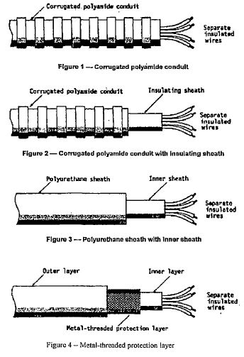
5.8.7.6.3 Lighting
Lamp bulbs with screw caps shall not be used.
5.8.7.6.4 Electrical Connections
Electrical connections between motor vehicles and trailers shall be of protection degree IP 54 in accordance with IEC 60529 and shall be designed to prevent accidental disconnection. Examples of appropriate connections are given in ISO-7638-1 and ISO-7638-2.
5.8.7.6.5 Electrical Bonding
The chassis, tank, piping and associated equipment, including all covers shall be bonded together so as to ensure electrical continuity. This bonding shall be connected to two clearly marked earthing points one on each side of the vehicle, each of which shall be connected to the earth bond wire when the tank is being filled or discharged. The final discharge electrical hose connection shall be bonded to the road tank vehicle or shall be completely insulated from the road tank vehicle by means of an insulating block or a non-conductive hose. (See also ZS 385-2). No earth point shall be insulated or painted.
5.9 Braking Equipment
5.9.1 General Requirements
Motor vehicles shall comply with the requirement of 5.9.2 and 5.9.3, in accordance with Table 1.
5.9.2 Anti-lock Braking System
5.9.2.1 Motor vehicles of GVM exceeding 16 000 kg, and motor vehicles authorised to tow trailers of GVM exceeding 10 000 kg, shall be equipped with anti-lock braking systems of category 1 in accordance with SANS 20013.
5.9.2.2 Trailers of GVM exceeding 10 000 kg shall be equipped with anti-lock braking systems of category A, in accordance with SANS 20013.
5.9.3 Endurance Braking System
5.9.3.1 Motor vehicles of GVM exceeding 16 000 kg, and motor vehicles authorised to tow trailers of GVM exceeding 10 000 kg, shall be fitted with endurance braking system. The system may be a single device or a combination of several devices and each device may have its own control.
5.9.3.2 The effectiveness of the endurance braking system shall be controlled by the anti-lock braking system so that the axle(s) braked by the endurance system cannot be locked by the endurance braking system at speeds above 15 km/h. This requirement shall not apply to that part of braking system constituted by natural engine braking.
5.10 Prevention of Fire Risks
5.10.1 Vehicle Cab
Any windows in the rear of the cab or in the shield shall be hermetically closed and shall be made of fire resistant safety glass with fire resistant frames that prevent the glass from falling out in the event of a fire. Furthermore there shall be a clear space of at least 150mm between the tank and the cab or the tank and the shield.
5.10.2 Fuel Tanks
In the event of any leakage from the fuel tank supply of the vehicle, the fuel shall drain to the ground without coming into contact with hot parts of the vehicle or the load.
5.10.3 Exhaust System
The exhaust shall discharge sideward on the right hand side of the vehicle at the point not closer than 1m from any tank outlet or liquid discharge point. Parts of the exhaust situated directly below the fuel tanks shall either have a clearance of at least 100 mm or be protected by a thermal shield.
5.10.4 Endurance Braking
5.10.4.1 Vehicles equipped with endurance braking systems that raise the temperature and that are placed behind the rear wall of the driver’s cab, shall be equipped with thermal shield, securely fixed and located between the system and the tank or load so as to avoid any heating, even local, of the tank wall or the load.
5.10.4.2 In addition, the thermal shield shall protect the braking system against any outflow or leakage, even accidental, of the load. Protection that includes a twin-shell shield is considered satisfactory.
5.10.5 Combustion Heaters for Heavy Fuel Oil and Bitumen Road Tank Vehicles
5.10.5.1 Combustion heaters and their exhaust gas routing shall be designed, located and protected or covered so as to prevent any unacceptable risk of heating or ignition of the load.
5.10.5.2 Combustion heaters shall be capable of being put out of operation by at least the following methods—
(a) intentional manual switching from the driver’s cab;
(b) stopping of the vehicle engine, in which case the heating device may be restarted manually by the driver; and
(c) start-up of a feed pump on the vehicle for the dangerous goods carried.
5.10.5.3 The combustion heater shall be switched on manually. Programming devices shall not be used.
5.11 Fire Extinguishers
5.11.1 One portable (1 kg to 4.5 kg maximum) dry chemical powder fire extinguisher, or any acceptable type, shall be carried in the cabin. The two portable fire extinguishers shall be carried on the outside of each road tank vehicle, one on each side. An extinguisher shall be of the multipurpose dry powder type (suitable for fires of classes A, B, and C) and shall comply with the relevant requirements of ZS 373 and be of capacity at least 9.0 kg. The suitable mounting position provided for the extinguishers must allow for easy access to the equipment.
5.11.2 Multiple combination vehicles shall carry one fire extinguisher per unit in the combination:
5.11.3 Rigid vehicles shall have two fire extinguishers and on a truck tractor, as in the case of ISO containers (see 5.8.5), there shall be two fire extinguishers.
5.12. Rear Bumper and Under Run
5.12.1 Stout steel guard s on the frame of the vehicle shall be used to protect the lower part of the rear of the tank and piping in the event of a collision and to minimise the possibility that the tank will be truck by any part of a colliding vehicle. The tank must not go beyond the chassis. The rear bumper shall be placed at least 300 mm beyond the rear end of the tank.
5.12.2 Road tank vehicles of GVM exceeding 3500 kg shall be fitted with rear and side under run protection devices at a maximum height of 500mm from the ground.
5.13. Manhole Covers
5.13.1 Manhole cover, including fill openings shall comply with the requirements of one of the following tests—
(a) a drop test (see 7.6.1) after which there shall be no leakage; or
(b) a pressure test (see 7.6.2).
5.13.2 The unit shall be structurally capable of withstanding, without leakage or permanent deformation that would affect its structural integrity, the greater of a static internal fluid pressure of 25 kPa or the tank test pressure (sec 7.2).
5.14. Tyres
The mechanical horse and drawbar trailer shall be fitted with non-retreaded front tyres (steering axle). All other tyres shall be in good condition as provided for in ZS 437. A combination of steel belted and nylon tyres on the same side of an axle is prohibited.
5.15. Speed Limiting Device
Road Tank Vehicles shall be fitted with speed limiters complying with ZS 675.
6. MARKING
6.1 Tanks
The tank serial number shall be stamped on a suitable part of the tank. Each tank shall in addition bear the following information legibly and durably marked on a flameproof data and inspection plate that is adequately secured to the tank or attached structure and that is preferably located on the left side (facing forward) of the tank near the front and in a place readily accessible for inspection—
(a) the manufacturer’s name, trade name or trade mark;
(b) the serial number of the tank;
(c) the date of manufacture;
(d) the date of test;
(e) the design pressure;
(f) the tank capacity in litres per compartment (front to rear);
(g) the maximum liquid load in kilograms;
(h) the maximum design liquid density in kilograms per cubic metre;
(i) the maximum fill rate in litres per minute and pressure, in kilopascals;
(j) the maximum discharge rate in litres per minute; and
(k) the Zambia Bureau of Standards certification mark (issued by ZABS).
6.2. Vents
Each vent shall be legibly and durably marked with its flow capacity and the pressure at which this was determined or with a reference number. Where a vent is marked with a reference number, the supplier shall provide in a pamphlet or booklet, details of the flow capacity and pressure for that reference number.
6.3. Warning Signs (HAZCHEM, Reflectors, No smoking, No Naked Flame and Switch Off Cell Phone)
6.3.1 For the purpose of fire handling alert, each tanker must carry HAZCHEM signs and adjacent No smoking and No Naked Flame signs at the rear and at the front side of the cargo tank (See Annex D).
6.3.2 The tank trailer must have high density orange reflectors along its sides for the safety of other road users. The reflectors shall be continuous along the sides of the tractor, tanks or trailer.
6.3.3 The rear of the trailer shall have a chevron and adequate red reflectors.
The tractor and the trailer(s) shall have certified number plates for easy identification.
7. INSPECTION AND METHODS OF TEST
7.1 Inspection
7.1.1 Visually examine and using any means that will provide the required accuracy, then measure the tank and components of the road tank vehicle for compliance with all the relevant requirements of clauses 5 and 6 which tests are not given in 7.2 to 7.6, inclusive. Ongoing inspection of road tank vehicles for flammable liquid shall include the evaluation of the operator’s quality system. In this connection it should be noted that ZS ISO 9001 covers the provisions of an integrated quality system.
7.1.2 Internal and External Inspection of the road tank vehicle shall be undertaken by an authorised inspections body at least once every two years. In addition to this requirement, the internal and external inspections shall be carried out after any major repairs are undertaken (e.g. road accident repairs, structural repairs).
7.1.3 A certificate shall be issued to show the test results of the inspection carried out as shown in 7.2 to 7.6.
7.2. Resistance of the tank to Hydrostatic or Pneumatic Pressure
7.2.1 With the manhole cover removed the manhole opening covered with a plate and all relief valves clamped, plugged or otherwise rendered inoperative, subject the tank to an internal hydrostatic or pneumatic test pressure equal to the higher of the marked design pressure (see 6.1(e)) or 35 kPa.
7.2.2 Maintain the pressure for a period of 30 minutes at 1.25 MAWP (Maximum Available Working Pressure) to verify that the tank does not burst or leak (see 5.4.1 and 5.4.5). If it is a compartmentalised tank, test each compartment separately, ensuring that the adjacent compartments are empty and at atmospheric pressure.
7.3. Hydrostatic or Pneumatic Testing of Pipes, Valves, Manifold and Fittings
Prior to attachment, subject each pipe, valve, manifold and fitting used for conveying liquid to an hydrostatic or a pneumatic test at the relevant pressure given in 5.5.4. Maintain the pressure long enough to detect any leaks.
7.4. Resistance of the Pumping System to Hydraulic Pressure
After final assembly subject, the entire pumping system (if fitted) of the road tank vehicle to a hydraulic pressure test at normal working pressure (sec 5.6.3). Continue pumping long enough to detect any leaks.
7.4.1 This shall be carried out to determine the residual thickness of the shell plate in comparison to the minimum allowable retirement thickness.
7.5 Welding Tests
These shall be carried out after any welding repairs on the tank as set out in ASME 9.
7.5.1 Pressure, Vacuum and Flow Testing of Vents
7.5.1.1 Apparatus
Shall consist of the following—
(a) steel test tank of depth 0.3m and of length and width 1 m each, suitably constructed to withstand a pressure of at least 50 kpa, with provision for mounting a manhole cover, adapters for fitting additional vents where required, and an 80 mm screwed inlet at the bottom;
(b) pressure gauge, capable of reading from – 10 kPa to + 100 kPa;
(c) pressure;
(d) air flow meter;
(e) water flow meter;
(f) exhauster;
(g) compressed air supply; and
(h) water supply.
7.5.1.2 Procedure
Fit in the normal operating positions the manhole cover, the hatch and where relevant any additional vent of the prototype.
7.5.1.2.1 Connect the exhauster, air flow meter and pressure gauge to the tank. Operate the exhauster, record the vacuum at which the vent starts to open and check normal vents for compliance with 5.5.3.1.
7.5.1.2.2 Where relevant, slowly increase the rate of exhaustion to a value corresponding to the maximum liquid discharging rate (see 6.1(j)). Check that filling and discharging vents do not allow the vacuum to exceed 7 kPa (see 5.5.3.2).
7.5.1.2.3 Disconnect the exhauster and replace it with the compressed air supply. Slowly introduce dry air and check the pressure at which the vent starts to open for compliance with 5.5.3.1, in the case of normal vents, and with 5.5.3.3(b), in the case of pressure actuated emergency vents.
7.5.1.2.4 Adjust the air flow until steady operating conditions are obtained at a pressure corresponding to the pressure claimed by the manufacturer (see 6.2). Except in the case of fusible vent record the flow rate and check for compliance with 5.5.3.4.
7.5.1.2.5 When relevant, adjust the air flow until a steady pressure of 35 kPa is obtained and check the flow rate of pressure actuated emergency vents for compliance with 5.5.3.3.
7.5.1.2.6 When relevant, adjust the rate of air flow to the maximum liquid filling rate for the tank (see 6.1 and check filling and discharging vents for compliance with 5.5.3.2).
7.5.1.2.7 Adjust the air flow to obtain a pressure in excess of 25 kPa, slowly decrease the air flow and check the pressure at which the emergency pressure vent closes for compliance with 5.5.3.3(b).
7.5.1.2.8 When relevant, connect the tank to the flow meter, pressure gauge and water supply. Adjust the flow rate to the maximum liquid filling rate for the tank (see 6.1(i) and check the filling vent for compliance with the relevant requirement of 5.5.3.2).
7.5.1.2.9 Dry the tank manhole cover and vents. Where a fusible vent is fitted remove the plug. Connect the air supply, flow meter and pressure gauge to the tank and by introducing dry air at a steady pressure of 35 kPa, verify that the total venting capacity of the emergency vents complies with 5.5.3.3(a).
7.5.1.2.10 Where a fusible vent is fitted with the plug removed and with all other vents scaled verify the accuracy of the flow rate claimed by the manufacturer (see 6.2 and 5.5.3.3(c)).
7.6 Testing of Manhole Covers (and Hatch Closures, When Fitted)
7.6.1 Drop Test
7.6.1.1 Conduct the test as follows—
(a) attach the base plate of the manhole cover, including the fill opening of the prototype (see NOTE (b) clause 1) to the end of a steel tube of such thickness that it will not distort during the test and that it has a length of 1.5 to 1.6 m and a shape such that the sealing ring of the base plate forms a liquid tight joint with the tube and with a suitable stop at the end of the tube;
(b) place the assembly in a suitable apparatus with the manhole cover at the bottom. Fill the tube with water to a depth of 0.9 m to 1.0 m;
(c) raise the assembly vertically to height of 1.45m to 1.55m (measured from its lowest point); and
(d) allow the tube and fitted manhole cover to fall freely through a distance of 1.20m – 1.21m and arrest the fall abruptly by means of the stop at the open end of the tube.
7.6.1.2 Consider the manhole cover (and hatch closure, if fitted) to have passed the test if the assembly remains liquid-tight throughout, except that sight is permissible on impact, provided that the leak stops immediately thereafter.
7.6.2 Pressure Test
Conduct the test as follows—
(a) fit each manhole cover including the fill opening with a safety device that prevents the cover from opening fully when internal pressure is present;
(b) secure each cover with fastening that will prevent opening of the covers as a result of vibration under normal conditions of transportation or of shock impact due to a rollover accident on the roadway or shoulder, provided that the area is not struck by a substantial obstacle; and
(c) mark each cover permanently by stamping or other means with—
(i) the manufacturers name;
(ii) the test pressure in kPa; and
(iii) a statement certifying that the manhole cover meets the pressure test requirements.
ANNEX A
(Normative)
NOTES TO PURCHASERS
The following requirements shall be specified in tender invitations and in each order or contact—
(a) the type and grade of metal required for the tank (see 5.2.1);
(b) the type of road tank vehicle;
(c) the total volume capacity of the tank in litres (see 5.3.2);
(d) when relevant, the orientation of oval manholes (sec 5.4.5);
(e) the normal working pressure of the pumping system (see 5.6.3);
(f) the length normal size maximum working pressure and type of hoses (see 5.7);
(g) whether lifting lugs arc to be fitted to demountable tanks (see 5.8.5);
(h) whether identification placard holders are to be fitted (see 5.8.6); and
(i) when relevant, the volume capacity of the individual compartments (see 5.3.2).
ANNEX B
(Normative)
INFORMATION TO BE SUPPLIED BY MANUFACTURER
The manufacturer shall supply the purchaser with the following information in the form of a data book with each road tank vehicle produced—
(a) details of the markings required for tanks and vents in terms of clause 6;
(b) design calculations that prove compliance with the relevant requirements of 5.3;
(c) where applicable, certificates covering the chemical analysis and tensile properties of the metal used for the construction of the tank piping and fitting (sec 5.2.1 and 5.2.2);
(d) where applicable, certificates covering the Charpy V-notch impact values for the metal and weld deposit used in the construction of the tank(s) (to prove compliance with the requirements of 5.2.1 and 5.4.2.2);
(e) weld procedure test results that prove compliance with 5.4.2;
(f) proof of compliance of the prototype and of road tank vehicles of the same model designation with the requirements for manhole covers (see 5.4.5), vents (see 5.5.3) and hoses (see 5.7); and
(g) the results of pressure tests carried out in accordance with 7.2 to 7.6.
ANNEX C
INSPECTION RECORD
Inspection of a road tank vehicle during and after its fabrication shall include the following items and shall be supported by a full detailed inspection report—
|
Sub clause |
Item inspected |
|
5.2.1 |
metal for tank; |
|
5.2.2 |
materials for pipes, fittings and other ancillary equipment; |
|
5.2.3 |
gasket joint rings and other components; |
|
5.2.4 |
other materials, if any; |
|
5.3.2 |
capacity of each tank; |
|
5.3.9 |
thickness of the shell, heads, bulk-heads and baffles; |
|
5.3.10 |
stiffening of heads, bulk-heads and baffles; |
|
5.3.11 |
circumferential reinforcement; |
|
5.4.2.1 |
welding-general; |
|
5.4.2.2 |
welds in steel and stainless steel; |
|
5.4.2.3 |
welds in aluminium alloys; |
|
5.4.3 |
baffle and ring stiffener joints; |
|
5.4.4 |
overturn protection; |
|
5.4.5 |
manholes and fill openings; |
|
5.5.2.1 |
valves – design and mounting; |
|
5.5.2.2 |
valve controls; |
|
5.5.3.1 |
normal vents; |
|
5.5.3.2 |
filling and discharging vents; |
|
5.5.3.3 |
emergency vents; |
|
5.5.4 |
piping and fittings; |
|
5.5.5 |
dip tubes; |
|
5.5.6 |
access to manholes and fill openings (ladder, catwalk, hand rail etc.); |
|
5.5.7 |
attachment of non-liquid carrying components; |
|
5.6.1 |
power source for pumping; |
|
5.6.2 |
pump; |
|
5.6.3 |
working pressure; |
|
5.7.1 |
normal hoses; |
|
5.7.2 |
aircraft fuelling hoses; |
|
5.8.1 |
cab; |
|
5.8.2 |
shielding of engines; |
|
5.8.3 |
chassis and mounting of tank; |
|
5.8.5 |
demountable tanks; |
|
5.8.6 |
placard and document holders; |
|
5.8.6.1 |
holders for identification placards, if applicable; |
|
5.8.6.2 |
document holder in cab; |
|
5.8.6.3 |
document storage container; |
|
5.8.7 |
electrical equipment; |
|
5.8.7.1 |
electrical system; |
|
5.8.7.2 |
wiring; |
|
5.8.7.3 |
battery master switch; |
|
5.8.7.4 |
battery; |
|
5.8.7.5 |
permanently energised circuits; |
|
5.8.7.6 |
electrical installation at the rear of the driver’s cab; |
|
5.9 |
braking system; |
|
5.10 |
prevention of fire risks; |
|
5.10.1 |
vehicle cab; |
|
5.10.2 |
fuel tanks; |
|
5.10.3 |
exhaust system; |
|
5.10.4 |
endurance braking; |
|
5.10.5 |
combustion heaters for heavy fuel oil and bitumen road tank vehicles; |
|
5.11 |
fire extinguishers; |
|
5.12 |
rear bumper and under run; |
|
5.13 |
manhole covers and openings; |
|
5.14 |
tyres; |
|
5.15 |
speed limiters; |
|
6 |
marking; |
|
6.1 |
marking of tanks; |
|
6.2 |
marking vents; |
|
7 |
inspection and methods of test; |
|
7.2 |
resistance of the tank to hydrostatic or pneumatic pressure; |
|
7.3 |
hydraulic or pneumatic testing of pipes, valves, manifolds and fittings; |
|
7.4 |
resistance of the pumping system to hydraulic pressure; |
|
7.5 |
pressure, vacuum and flow testing of vents; and |
|
7.6 |
testing of manhole covers (and hatch closures, when fitted). |
ANNEX D
(Normative)
REFLECTOR AND HAZCHEM SIGN POSITIONS
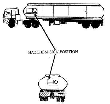
ANNEX E
(Normative)
ELECTRICAL INSPECTION AND TESTING CHECK LIST
Under listed are mandatory electrical checks for a road worthy vehicle. These checks shall be considered to the minimum requirements.
Vehicle registration number:
Check serviceability of— Condition
1. Battery master switch
2. Battery electrolyte and terminals
3. Battery bracket and cover
4. Indicator and lenses
5. Parking lights and lenses
6. Brake lights and lenses
7. Headlights and lenses
8. Wipers
9. Horn
10. Starter motor cables and connections
11. Charging system
12. Ignition system
13. General cable insulation and wiring
14. Tachograph
15. Bonding cable
16. Earth pins
VALIDITY PERIOD: Three months
DATE OF ISSUE:
EXPIRY DATE:
CHECKED BY: Company name:
Address:
Name of Inspector:
Qualification:
Signature:
ANNEX F
(Informative)
NOTE ON THE USE OF THE CERTIFICATION MARK
The Zambia Bureau of Standards is the owner of the registered certification mark shown below, the independent assurance that the product complies with the requirements of this Zambian Standard.
This certification mark may be used by manufacturers only under license from the Zambia Bureau of Standards. Particulars of the conditions under which licenses are granted may be obtained from the Executive Director, Zambia Bureau of Standards, P.O. Box 50259, LUSAKA, 15101, Zambia.

Manufacturers producing road tank vehicles to this Standard may, under a licence issued by the ZABS, apply the certification mark as illustrated above to the commodity as evidence to the purchaser that the commodity is being made in accordance with the standard and that compliance with its requirements is met and inspections carried out by ZABS.
NOTES:
1. In terms of the Standards Act, Cap. 416 of the Laws of Zambia, it is a punishable offence for any person, other than a licence holder, to apply a certification mark to a commodity, to refer to the ZABS or any of its standards in a manner likely to create the impression that the commodity has been approved by the ZABS.
Furthermore, a person shall not claim or declare that the person or any other person complied with a standard unless—
(a) such claim or declaration is true and accurate in all material respects; and
(b) the identity of the person on whose authority such claim or declaration is made is clear.
2. It is recommended that authorities who wish to incorporate any part of this standard into any legislation in the manner intended by section 14 of the Act, consult ZABS regarding the implications.
ZAMBIA BUREAU OF STANDARDS
Zambian Standard ZS 429-4:2011
THE HANDLING STORAGE, AND DISTRIBUTION OF LIQUEFIED PETROLEUM GAS (LPG) IN DOMESTIC, COMMERCIAL, AND INDUSTRIAL INSTALLATIONS
Part 4: Transportation of LPG in Bulk by Road – Code of Practice
1. SCOPE.
1.1 This part of the code of practice contains recommendations for the design, construction, inspection, fittings and filling ratio of tanks used in the transportation of LPG in bulk by road, the design of vehicles and ancillary equipment, and operating practice.
1.2 Fire precautions are also covered, but protection against a major fire outbreak that leads to direct flame impingement on the vehicle cargo tank for any considerable period cannot be provided for in the design features. Sound engineering land good operating practice will lead to the avoidance of this contingency and, where thought necessary, recommendations are made in respect of these aspects.
1.3 The suitability of vehicle cargo tanks for use under cold temperature conditions has been provided for in the design parameters of the tank.
1.4 The attention of users of this part of the code is drawn to the “Hazchem” system of marking of tankers, which is at present finding wide application in industry, to identify (particularly for the purpose of indicating the actions required of Fire Authorities in the case of accidents involving such tankers) the hazardous product that is being conveyed. The adoption of such a system for the identification of LPG road tankers is mandatory.
NOTE:
Where the contents of supply vehicles are to be transferred by fixed compressor or pump to the storage tank of the consumer, the recommendations given in this part of the code shall be followed. Any additional requirements shall be agreed upon between the supplier and the consumer and shall be to the satisfaction of the approving authority.
2. NORMATIVE REFERENCES
The following Standards and legislation contain provisions that, through reference in this text, constitute provisions of this part of ZS 429 Standard—
|
ZS 429-2: |
The Handling, Storage and Distribution of Liquefied Petroleum Gas in Domestic, Commercial and Industrial Installations – Code of Practice; |
|
ZS 372: |
Transportation of Petroleum Products: Operational Requirements |
|
for Road |
Tank Vehicles – Code of Practice; |
|
SANS 1186: |
Symbolic Safety Signs; |
|
IEC 60529: |
2001/SANS 60529: 2001: Degrees of Protection provided by enclosures (IP Vode); |
|
The Mines and Minerals Development Act, No. 7 of 2008; |
|
|
The Occupational Health and Safety Act, No. 36 of 2010; |
|
|
The Factories, Act, Cap. 441 of the Laws of Zambia; |
|
|
The Public Roads Act, No. 12 of 2002; and |
|
|
The Road Traffic Act, No. 11 of 2002. |
NOTE:
All Standards are subject to revision and, since any reference to a Standard is deemed to be a reference to the latest edition of that Standard, parties to agreements based on this part of ZS 429 are of the most recent editions of the Standards indicated below. Information on the currently valid National and International Standards can be obtained from the Zambia Bureau of Standards.
3. DEFINITIONS
For the purposes of this part of the Standards, the following definitions apply—
3.1 Approved
Approved by the approving authority.
3.2 Approving Authority
(a) The Weights and Measures Act, Cap. 403;
(b) The Energy Regulation Act, Cap. 436;
(c) The Petroleum (Exploration and Production) Act, No. 10 of 2008;
(d) The Road Traffic Act, No. 11 of 2002;
(e) The Public Roads Act, No. 12 of 2002;
(f) The Occupational Health and Factories Act, Cap. 441;
(g) The Environmental Management Act, No. 12 of 2011;
(h) The Mines and Minerals Act, No. 7 of 2008; and
(i) The Local authority concerned (within the scope of the jurisdiction of local authorities).
3.3 Filling Ratio
The ratio of the mass or volume of LPG introduced into a tank to the mass or volume of water (determined at, or corrected to 20°C for Volume) that would fill the tank.
NOTE: The term “filling ratio” applies when the filling of a container with liquefied gas is controlled on the basis of the mass of gas introduced.
3.4 Liquefied Petroleum Gas (LPG)
Commercial butane, commercial propane, or a mixture of light hydrocarbons (predominantly propane, propene, butane and butene) that is gaseous under conditions of ambient temperature and pressure and that is maintained in the liquid state by an increase of pressure or a lowering of temperature.
NOTE: Commercial butane, liquefied petroleum gas mixtures and commercial propane are covered by ZS 426.
3.5 Maximum Permissible Service Pressure
The maximum internal pressure that is permitted for a tank during service.
3.6 Semi-trailer
A trailer having no front axle and so designed that at least 15% of its tare is superimposed on and borne by a vehicle drawing the trailer.
3.7 Tank
A pressure vessel designed for the conveyance of LPG and as defined in, and complying with, the regulations framed under ZS 429, Part 2, the Occupational Health and Safety Act, No. 36 of 2010, the Factories Act, Cap. 441 of the Laws of Zambia and the Mines and Minerals Development Act, No. 7 of 2008.
NOTE: A tank that is suitable for the conveyance of commercial propane may also be used to convey commercial butane and LPG mixtures.
4. DESIGN, CONSTRUCTION AND TESTING OF CARGO TANKS
4.1 General
4.1.1 Cargo tanks shall be designed and constructed in accordance with ZS 429, Part 2, or its equivalent, sound engineering practice and the relevant regulations framed under the Occupational Health and Safety Act, No. 36 of 2010, and the Factories Act, Cap. 441 of the Laws of Zambia.
4.1.2 In the case of a large tank, suitable buffer plates shall be provided to minimise surging of the contents.
4.2 Capacity
The gross laden mass of the tank is determined by the design capacity of the vehicle. Unless otherwise allowed, the axle loadings of vehicles must be in accordance with the appropriate requirements of the Public Roads Act, No. 12 of 2002.
4.3 Connecting Points and Manholes
Connecting points shall be provided with studs for flanged fittings. Connections shall be designed to withstand the most severe combined stresses to which they may be subjected by the pressure of the LPG, the pumping pressures and shock loadings caused by transport conditions.
Each tank shall be provided with a manhole or with inspection openings such that the whole of the interior can be examined.
Wherever possible, fixtures or connections that may trap water shall be avoided.
4.4 Gauges and Fittings
4.4.1 General
4.4.1.1 All gauges and fittings shall be suitable for use in the range of temperatures and pressures for which the tank has been designed, shall be able to withstand normal road shocks and shall be protected against physical damage and tampering.
4.4.1.2 It is recommended that gauges be placed so that they can be read from ground level.
4.4.1.3 Instrument drain cocks, sampling valves and other shut-off valves that communicate directly with the outer atmosphere and that are not in use shall be fitted with caps or blank flanges.
4.4.1.4 Provision shall be made for the connection of bonding leads, where applicable (see 8.5).
4.4.2 Contents Gauge
Each tank shall be equipped with a contents-gauging device that is subject to the relevant of the following precautions—
(a) each gauging device (such as a rotary tube, fixed tube or slip tube) that relies on bleeding to the atmosphere shall be so designed that—
(i) unless it is protected by a suitable emergency shut-off valve, the maximum opening of the bleed hole does not exceed 1.4 mm; and
(ii) it cannot be withdrawn completely during normal gauging operations;
(b) any maximum liquid level indicator shall be located as near to the midpoint (front to rear) of the tank as is practicable and shall be readily accessible; and
(c) if the contents of the tank are to be measured with a rotary tube, magnetic or slip-tube gauge, at least one fixed tube gauge, set at 85% of the water capacity of the tank, shall in addition be provided for checking the accuracy of the variable gauge.
4.4.3 Temperature Gauge
4.4.3.1 Each tank shall be provided with a suitable temperature measuring instrument. Bulbs or sensing heads of temperature measuring instruments shall not be mounted in direct contact with the contents of a tank unless they are fire proof, of high resistance to fracture and designed to operate at a pressure of at least 1,725 kPa.
4.4.3.2 For standard instruments, thermometer pockets (in the form of blind tubes of suitable strength and filled with oil) shall be permanently fitted into a tank in a manner that complies with the standard to which the tank is constructed.
4.4.4 Pressure Gauge
Each tank shall be equipped with a suitable pressure gauge connected to the vapour space of the tank. Pressure gauge connections shall be protected internally by means of a suitable excess-flow valve, or by a pressure tapping reduced internally to a bleed hole of diameter not exceeding 1.4 mm, and a manually-operated isolating valve shall be fitted externally between the tank and the pressure gauge.
4.4.5 Pressure-Relief Devices (see also the relevant regulations framed under the Occupational Health and Factories Act, Cap. 441 of the Laws of Zambia).
4.4.5.1 Each tank shall be equipped with at least one pressure-relief device (of stainless steel spring-loaded of equivalent type), each having direct communication with the vapour space of the tank.
4.4.5.2 Each pressure-relief device shall be set to start to discharge at a pressure in the range 1,725-1,900 kPa (inclusive), and shall be of such size and so designed and installed that the device discharges (at not less than the appropriate rate given in Table 1) before the pressure in the tank exceeds 2,070 kPa.
4.4.5.3 Pressure-relief devices shall be such that it is not possible to tamper with the relief-valve settings.
4.4.5.4 Emergency shut-off valves shall not be installed between a tank and any pressure-relief device except as allowed in terms of 4.4.5.5.
4.4.5.5 The size and the number of pressure-relief devices shall be sufficient to provide the full relief flow capacity required for the tank when any one is inoperative.
4.4.5.6 Provision may be made to isolate any relief valve for testing or servicing provided that the provisions of 4.4.5.4 are observed and that the remaining relief valve or relief valves provide the full relief capacity required in terms of 4.4.5.1.
4.4.5.7 Each pressure-relief device shall be legibly and permanently marked with the following—
(a) the pressure at which the device is designed to open; and
(b) the maximum discharge rate of air in cubic metres per second at ambient temperature and pressure (see Table 1).
4.4.5.8 Pressure-relief devices shall be tested for accuracy of set-to-discharge pressure at intervals that do not exceed five years.
4.4.5.9 The pressure-relief device shall vent upward, away from the tank, along an unobstructed path and into the open air.
4.4.5.10 The vents shall be fitted with loose-fitting rain caps drained at the bottom, the drain holes being so positioned as not to permit venting of vapour or liquid directly on the surface of the tank.
4.4.6 Emergency Shut-off Valves
4.4.6.1 Subject to the provisions of 4.4.5.1 all liquid and vapour connections in the tank, other than those for pressure relief valves and gauges for measuring temperature, pressure and liquid content and those permanently fitted with blank flanges, shall be fitted with an emergency shut-off valve (e.g. an excess-flow valve, an automatically operated valve or a remotely controlled valve) or a non-return valve.
4.4.6.2 As sludge, scale, dirt, etc. may cause excess-flow valves and non-return valves to stick in the open position, drain outlets need not be fitted with such valves, provided that the drain is fitted with two valves (one of which is of the quick-closing type) not less than 600 mm apart.
4.4.6.3 Where the emergency shut-off valve is of the excess-flow type, the rate of flow required to close it shall be less than that likely to result from a complete fracture of the line it is protecting (calculated under the most adverse conditions likely to be experienced) and in no case shall it exceed 1.5 times the design flow for the line.
4.4.6.4 Excess-flow valves shall have a rated closing capacity sufficiently above normal flow requirements to prevent valve chatter.
4.4.7 Protection of Valves and Accessories
All valves and accessories shall be safe-guarded against interference and accidental damage. They shall be mounted and protected in such a way that risk of accidental rupture of the branch to which they are connected is minimised. In addition, valves at the rear of a vehicle shall be mounted so that they are protected from damage by the rear cross-member of the frame of the vehicle.
TABLE 1: RATE OF DISCHARGE OF PRESSURE-RELIEF DEVICES (FOR TANKS OF SURFACE AREA UP TO 200 M2)*
|
Surface Area, m2 |
Flow Rate m3/s of Air, min. |
Surface Area, m2 |
Flow Rate m3/s of Air, min. |
Surface Area, m2 |
Flow Rate m3/s of Air, min. |
|
<<1.5 |
0.248 |
16.5 |
1.77 |
55.0 |
4.75 |
|
2.0 |
0.313 |
17.0 |
1.81 |
60.0 |
5.10 |
|
2.5 |
0.377 |
17.5 |
1.86 |
65.0 |
5.45 |
|
3.0 |
0.437 |
18.0 |
1.90 |
70.0 |
5.79 |
|
3.5 |
0.497 |
18.5 |
1.94 |
75.0 |
6.13 |
|
4.0 |
0.553 |
19.0 |
1.99 |
80.0 |
6.46 |
|
4.5 |
0.610 |
19.5 |
2.03 |
85.0 |
6.79 |
|
5.0 |
0.665 |
20.0 |
2.07 |
90.0 |
7.11 |
|
5.5 |
0.718 |
21.0 |
2.16 |
95.0 |
7.44 |
|
6.0 |
0.772 |
22.0 |
2.24 |
100.0 |
7.75 |
|
6.5 |
0.825 |
23.0 |
2.32 |
105.0 |
8.07 |
|
7.0 |
0.877 |
24.0 |
2.41 |
110.0 |
8.39 |
|
7.5 |
0.927 |
25.0 |
2.49 |
115.0 |
8.70 |
|
8.0 |
0.977 |
26.0 |
2.57 |
120.0 |
9.01 |
|
8.5 |
1.03 |
27.0 |
2.65 |
125.0 |
9.31 |
|
9.0 |
1.08 |
28.0 |
2.73 |
130.0 |
9.62 |
|
9.5 |
1.13 |
29.0 |
2.81 |
135.0 |
9.92 |
|
10.0 |
1.17 |
30.0 |
2.89 |
140.0 |
10.2 |
|
10.5 |
1.22 |
31.0 |
2.97 |
145.0 |
10.5 |
|
11.0 |
1.27 |
32.0 |
3.05 |
150.0 |
10.8 |
|
11.5 |
1.32 |
33.0 |
3.12 |
155.0 |
11.1 |
|
12.0 |
1.36 |
34.0 |
3.20 |
160.0 |
11.4 |
|
12.5 |
1.41 |
35.0 |
3.30 |
165.0 |
11.7 |
|
13.0 |
1.46 |
36.0 |
3.36 |
170.0 |
12.0 |
|
13.5 |
1.50 |
37.0 |
3.43 |
175.0 |
12.3 |
|
14.0 |
1.55 |
38.0 |
3.51 |
180.0 |
12.6 |
|
14.5 |
1.59 |
39.0 |
3.58 |
185.0 |
12.8 |
|
15.0 |
1.64 |
40.0 |
3.66 |
190.0 |
13.1 |
|
15.5 |
1.68 |
45.0 |
4.03 |
195.0 |
13.4 |
|
16.0 |
1.72 |
50.0 |
4.39 |
200.0 |
13.7 |
|
*For tanks with a total outside surface area greater than 200 m2, the required flow rate can be calculated from the following formula— |
|||||
|
Flow rate, m3/s of air = 0.17763 A0.82 |
4.5 Mountings
The mounting structure shall be of steel and so designed as to limit, as far as is practicable, movement of the tank in relation to the chassis of the vehicle. The design of the mounting structure, based on the ultimate strength of the material used, shall be such that, subject to a safety factor of at least four, the structure will withstand a static load in any direction equal to twice the weight of the tank and attachments when the tank is filled with the maximum mass of liquid permitted (see 4.2). Where the mounting structure is designed as an integral part of the tank shell, it shall be continuously welded to the shell.
4.6 Finish and Marking
4.6.1 Finish
Tanks shall be painted with a suitable corrosion-resistant and light-reflective paint.
4.6.2 Marking
A plate, securely attached to the shell of the tank in a conspicuous place, shall, in the terms of the relevant statutory regulations, be marked by the manufacturer with the following information—
(a) manufacturer’s name;
(b) country of origin;
(c) manufacturer’s serial number;
(d) year of construction;
(e) date of initial pressure test (4.7.1);
(f) test pressure, in kilopascals;
(g) maximum permissible service pressure, in kilopascals;
(h) water capacity, in cubic metres (or litres) at 20°C; and
(i) number and title of the standard to which the tank was constructed.
4.7 Inspection and Testing
4.7.1 Initial—
(a) tanks shall be constructed and subjected to initial inspection and testing, under the supervision of an approved inspecting authority, in accordance with the appropriate requirements of the ZS 429 Part 2; and
(b) a certificate giving the following information shall be provided with each tank—
(i) maximum permissible service pressure;
(ii) water capacity, in cubic metres (or litres) at 20°C;
(iii) date of test;
(iv) pressure at which tested;
(v) number and title of the standard to which the tank was constructed; and
(vi) any other data considered necessary.
4.7.2 Periodic
Each tank shall be subjected to periodic inspection and testing in accordance with the appropriate regulations framed in this Standard.
NOTE: It must be noted that only the approving authorities may grant permission for deviation from requirements for inspection and testing.
5. FILLING RATIOS AND FILLING OF TANKS
5.1 Filling Ratios
The safe filling ratio of a tank is a function of ambient temperature conditions. Table 2 gives the appropriate values for the maximum permissible filling ratios for LPG.
|
TABLE 2: FILLING RATIOS |
||
|
Relative density of LPG at 15°C/4°C |
Maximum Permissible Filling Ratios |
|
|
|
Tanks of capacity less than 5000 litres |
Tanks of capacity 5000 litres or more |
|
0.495 – 0.499 |
0.42 |
0.45 |
|
0.500 – 0.504 |
0.43 |
0.45 |
|
0.505 – 0.509 |
0.43 |
0.46 |
|
0.510 – 0.514 |
0.44 |
0.47 |
|
0.515 – 0.519 |
0.44 |
0.47 |
|
0.520 – 0.524 |
0.45 |
0.48 |
|
0.525 – 0.529 |
0.46 |
0.49 |
|
0.530 – 0.534 |
0.46 |
0.49 |
|
0.535 – 0.539 |
0.47 |
0.50 |
|
0.540 – 0.544 |
0.47 |
0.50 |
|
0.545 – 0.549 |
0.48 |
0.51 |
|
0.550 – 0.554 |
0.49 |
0.52 |
|
0.555 – 0.559 |
0.49 |
0.52 |
|
0.560 – 0.564 |
0.50 |
0.53 |
|
0.565 – 0.569 |
0.50 |
0.53 |
|
0.570 – 0.574 |
0.51 |
0.54 |
|
0.575 – 0.579 |
0.52 |
0.55 |
|
0.580 – 0.584 |
0.52 |
0.55 |
|
0.585 – 0.589 |
0.52 |
0.56 |
|
0.590 – 0.594 |
0.53 |
0.56 |
|
0.595 – 0.599 |
0.54 |
0.57 |
|
0.600 – 0.604 |
0.55 |
0.58 |
|
NOTE: The relative density is represented by the ratio of the mass of LPG at 15°C to that of water at 4°C |
5.2 Filling by Mass
The maximum mass, M (in kilograms), of liquid that may be introduced into a tank may be calculated from the following formula—
M = C x D
Where—
C = water capacity of the tank, kg; and
D = filling ratio.
5.3 Filling by Volume
5.3.1 The maximum volume (at a particular temperature, T) of liquid, VT, (expressed as a percentage of total tank capacity) that may be introduced into a tank may be calculated from the following formula, the temperature of the LPG being obtained by means of a thermometer placed in a thermometer pocket installed in the tank—

Where—
D = filling ratio
G = relative density of the LPG at 20°/20°C
F = liquid volume correction factor (see IP 250 and consider the relative density at 20°/20°C to be the density at 20°C);
T = temperature of liquid LPG in the tank, °C.
5.3.2 The actual maximum volume of LPG that may be introduced into the tank is obtained by multiplying the water capacity of the tank by VT/100.
6. VEHICLES
6.1 General
6.1.1 Vehicles used for the transportation of LPG shall comply with the appropriate requirements of the Public Roads Act No. 12 of 2002 and the Road Traffic Act, No. 11 of 2002.
6.1.2 LPG shall not be transported in a tank mounted on a conventional draw-bar trailer.
6.1.3 More than one tank may be mounted on a single chassis.
6.1.4 Separate hand-operated rear wheel braking, controlled from the cab, is recommended for semi-trailers.
6.1.5 The tank shall be either a component part of the chassis of the vehicle or securely attached to the chassis.
6.1.6 A composite vehicle carrying a tank or tanks shall be deemed to comply with (e) above if each tank, though removable, is securely fastened to a cradle that is fixed to the chassis, or, in the case of an ISO container tank designed for the conveyance of LPG, it is properly secured (see ISO 3874) to the carrying vehicle through its bottom corner fittings by means of acceptable securing devices, e.g. twist locks or pin securing devices.
6.2 Protection Against Fire and Electrical Hazards (See Also ZS 402 and SANS 10089: Part II)
6.2.1 Fire Precautions
6.2.1.1 A quick-action cut-off valve is not required in the fuel line if the fuel supply of the vehicle is not gravity-fed but supplied by a feed pump driven directly from the engine. However, such a valve shall be fitted to any vehicle that has a gravity-fed fuel supply.
6.2.1.2 If the fuel used to propel the vehicle gives off a flammable vapour at a temperature below 55°C, the vehicle shall not be allowed to tow an LPG trailer.
6.2.1.3 If a window is provided in the back of the cab, it shall be non-opening and of wired glass (or other approved heat resisting material) fitted in fire-resisting framing.
6.2.1.4 The exhaust system of the vehicle, including the muffler and the exhaust pipe, shall have ample clearance from the fuel system and any combustible material in the vehicle. The exhaust discharge shall be directed away from any tank and its appurtenances, and to the outside of the frame of the vehicle and any skirting of the vehicle. A muffler cut-out shall not be used.
6.2.1.5 Stout steel guards or the frame of the vehicle shall be used to protect the lower part of the rear of the tank from damage.
6.2.1.6 One fire extinguisher (dry chemical powder type with a B:C rating of at least 1 kg) shall be provided in the cab of the vehicle to be used as a first defense against a fire in the engine compartment.
6.2.1.7 At least two 9 kg serviceable fire extinguishers of the dry chemical powder type, located in an accessible position, shall be carried on each side of the vehicle.
6.2.1.8 Vehicle drivers and their assistants shall not smoke or allow smoking on or near the vehicle (within 15 metres around the vehicle) whether it is stationary or in motion, or while deliveries are being made or filling of the tank(s) is in progress, or while any repairs to the vehicles are being carried out.
6.2.1.9 Vehicle drivers and their assistants shall not use cell phones or allow usage of cell phone in or near (within 15 metres) the vehicle whether it is stationary or in motion, or while deliveries are being made or filling of the tank is in progress, or while any repairs to the vehicle are being carried out. The cell phone shall remain off during the aforementioned operations.
6.2.1.10 Each vehicle shall carry non-metallic chocks and anti-tow away device which shall be used to prevent rolling of the vehicle when it is parked and during loading and unloading.
6.2.2 Electrical Precautions
6.2.2.1 Electrical Equipment
Electrical System
The electrical system shall comply with the requirements given below and shall be certified through a valid electrical certificate issued by a qualified auto-electrician registered with the Engineering Institution of Zambia.
6.2.2.2 Wiring
(a) the conductors shall be large enough to avoid over-heating. Conductors shall be adequately insulated. All circuits shall be protected by fuses or by automatic circuit breakers, except for the following—
(i) from the battery to the cold start and stopping systems of the engine;
(ii) from the battery to the alternator;
(iii) from the alternator to the fuse or circuit breaker box; and
(iv) from the battery to the starter motor and from the battery to the power; control housing of the endurance braking system if this system is electrical or electromagnetic;
(b) the above protective systems shall be as short as possible; and
(c) the cables shall be securely fastened and positioned in such a way that the conductors are adequately protected against mechanical and thermal stresses.
6.2.2.3 Battery Master Switch
(a) the vehicle shall be fitted with a master switch comprising the following requirements;
(b) a four pole isolating switch for breaking the electrical circuits shall be placed as close to the battery as is practicable, it shall be protected against inadvertent operation and shall be easily operated by someone standing next to the vehicle;
(c) the switch shall have a casing with protection degree ip65 (dust tight and protected against water) in accordance with IEC 60529;
(d) the cable connections on the switch shall be of protection degree ip54 (protects against water and dust), however this does not apply if these connections are contained in housing, such as the battery box, in this case it is sufficient to insulate the connections against short circuits, for example with rubber cap; and
(e) the switch shall be labelled.
6.2.2.4 Battery
(a) the battery terminals shall be electrically insulated or covered by a non-conducting battery box cover, except that where the batteries are not located under the engine bonnet they shall be fitted with vented box;
(b) the battery shall be easily accessible;
(c) the batteries shall be properly secured by clamping to ensure minimum movement; and
(d) batteries with cell to cell connection exposed shall not be allowed.
6.2.2.5 All portable lighting equipment shall conform to ZS 402, or any other relevant standards.
6.2.2.6 Lighting circuits shall have suitable over-current protection such as fuses or automatic circuit-breakers.
6.2.2.7 All electrical circuits shall be heavily insulated and independent of the chassis except that the chassis may be used as the earth return for starter and ignition high voltage circuits
6.2.2.8 The wiring shall have adequate carrying capacity and mechanical strength and shall be so fixed, insulated and protected as to minimise accidental damage and undue wear.
6.2.2.9 The generator switches and fuses shall be in front of the cab. The battery shall, preferably, also be in front of the cab, but where this is impracticable, adequate precautions shall be taken.
6.2.2.10 The tank, ancillary equipment, pipe circuit and hoses shall have electrical continuity with the chassis, including the axles and springs.
6.3 Warning Notices
Each vehicle shall display at least two notices, one on each side of the vehicle, that are painted on or securely attached to the sides of the vehicle and that consist of the following words or of the corresponding pictogram (i.e. Types PV1, PV2 and PV3) given in SANS 1186—
DANGER—NO SMOKING—NO NAKED LIGHTS—SWITCH OFF CELL PHONE
The notices shall be printed in black letters on a yellow background (see also SANS 10140) and in English, in letters of height at least 60 mm in the case of the word “DANGER” and of height at least 30 mm in the case of the remainder of the wording. (Warning Signs).
6.4 Inspection
The roadworthiness of the vehicle shall be checked daily, in accordance with the Road Traffic Act, No. 11 of 2002. An example of a checklist is given in Annex A.
6.5 Maintenance
Each vehicle, its pipe-work, hoses and ancillary equipment shall be overhauled at frequent and regular intervals as per manufacturer specification.
7. ANCILLARY EQUIPMENT
7.1 Pumps
7.1.1 The design and construction of each pump shall be suitable for the duty for which it is required (see ZS 402 or any other relevant standard).
7.1.2 The pump body shall be made of non-porous, non-flammable materials capable of withstanding the jarring and vibration effects incident to vehicular use.
7.1.3 The rotational speed of the drive shall be suitably controlled to prevent the rating of the pump from being exceeded.
7.1.4 Pumps shall be protected from accidental damage by suitable positioning.
7.1.5 If electrically operated pumps are employed, the electrical installation shall be flame-proof (see also ZS 402 and SANS 10089: Part 2).
7.1.6 In the case of a hose that is carried on the vehicle and that is connected to the pump discharge piping, an automatic device (such as a differential regulator or equivalent device) shall be installed between the discharge piping and the hose connection to prevent discharge of liquid when the pump is not in operation. If a meter is fitted to the discharge piping, the device shall be installed between the meter outlet and the hose connection. An excess-flow valve may also be used but shall not be the exclusive means of putting the recommendations mentioned above into practice.
7.2 Meters
7.2.1 The design and construction of each meter shall be suitable for the duty for which it is required.
7.2.2 The meter body shall be made of non-porous, non-flammable materials capable of withstanding the jarring and vibration effects incident to vehicular use.
7.2.3 Meters shall be protected from accidental damage by suitable positioning.
7.2.4 Should a meter be used for trade purposes, it shall be certified in accordance with the Weights and Measure Act, Cap. 403 of the Laws of Zambia.
7.3 Pipe-Work and Pipe Fittings
7.3.1 All pipe-work and pipe fittings shall be designed in accordance with an approved code for piping systems carrying fluids subject to pressure, such as ASME B31, BS 3351, BS 3602 and ISO 15649.
The purchaser shall specify the applicable design code or specification with which the pipe-work and pipe fittings are to comply. Piping shall be so sized as to provide adequately for the required flow rate.
7.3.2 Any portion of piping between a tank and a pump inlet, and any hose or piping that contains liquid and that may at any time be closed at each end, shall be provided with a hydrostatic relief valve having a pressure setting of 3 000 kPa.
7.3.3 Pipe joints may be flanged or welded. Adequate provision shall be made for movement between a tank and the chassis that may affect connections. This may be accomplished by using flexible connections.
7.3.4 All welded joints shall be subject to examinations and tests during and after production, as prescribed in the relevant code of practice or specification.
The quality of each weld shall be at least equal to that prescribed for a Grade A weld in SANS 10044: Part III. The quality of the welds shall be established by examination of at least 10% of all welded joints by radiographic or ultrasonic methods for butt welds or by magnetic particle and dye penetrant methods where radiography cannot be applied.
NOTE: It is advisable to lay down a specific procedure for additional examination in case the initial examination shows unsatisfactory results.
7.3.5 All piping and fittings, as well as pumps and meters, permanently mounted on a vehicle must be designed to withstand the most severe combined stresses imposed by the following—
(a) the vapour pressure of the product under maximum temperature conditions; and
(b) either—
(i) the superimposed pumping pressure; or
(ii) the shock loadings caused by road movements.
7.3.6 Neither piping nor fittings shall project beyond the sides or the ends of a vehicle. All piping and equipment must be adequately protected to minimise accidental damage that might be caused by rough usage, collision or overturning.
7.3.7 All piping and fittings shall be tested (at a pressure of at least 3 000 kPa) after assembly and shall not be put into service until certified free from leakage.
7.3.8 Aluminium or aluminium alloy pipe or tubing shall not be used.
7.4 Hoses
7.4.1 Hoses for the conveyance of LPG shall be resistant to the solvent action of the gas. They must be designed to withstand a minimum bursting pressure of five times the maximum pressure to which they will be subjected in service. (This maximum pressure is equal to the vapour pressure of the LPG under maximum temperature conditions plus the differential pumping pressure.)
NOTE: Hoses complying with BS 4089 have been found to satisfy these requirements (see also SANS 1156: Part 1).
7.4.2 Hoses in service shall be visually examined every day for—
(a) wear caused by abrasion of outer cover;
(b) cuts, gouges, tears and other damage that may affect the condition of the hose braiding;
(c) wear of the hose braiding;
(d) chafing and kinking;
(e) damage that causes leakage and insecurity of end-couplings;
(f) damage to any part of the hose that may cause leakage; and
(g) bulges, ballooning or unusual soft spots.
Where any such damage is noticed, the hose must not be used until it has been repaired and hydraulically tested at its service pressure.
7.4.3 The following tests on hoses must be conducted at regular intervals not exceeding six months—
(a) a hydraulic test at the service pressure, the results being recorded; and
(b) a test for electrical continuity.
7.4.4 Hoses must be rejected at the end of a service period not exceeding three years or as per manufacturers expiry date (whichever comes first).
7.4.5 On a vehicle, hoses shall be so carried that they are protected from accidental damage.
8. DRIVER INSTRUCTION AND TRAINING
8.1 A high standard of driving skill (shall have passed handling of dangerous goods training and shall be in possession of a PSV driving licence for the vehicle code that corresponds to the type of vehicle he intends to drive) and physical fitness is required for drivers. Other requirements shall be as detailed in ZS 372.
8.2 Drivers shall be certified medically fit to drive by a doctor recognised by the Medical Council of Zambia. Extra medical checks, such as annual checks and proficiency test for the driver shall be done (if considered necessary) after absence from work for over thirty days owing to illness or any other cause.
8.3 Every vehicle while engaged in the conveyance of LPG shall, except while halted at a place approved for the purpose by the local authority or as allowed in terms of 9.1, be constantly attended to by the driver or other competent person who is at least 25 years of age.
8.4 When a vehicle is stationary, the driver (or other competent person who is at least 25 years of age) may be regarded as being in attendance of it if he is within 15 metres from the tank in whatever direction.
8.5 A semi-trailer, while attached to a drawing vehicle, shall be regarded as forming part of the vehicle to which it is attached and shall not be regarded as a separate vehicle.
8.6 Safe operating methods for the conveyance of LPG, the filling of tanks with LPG, the discharge of LPG, use of correct PPE and emergency procedures shall be covered during instruction and training of the driver.
9. FILLING OF TANKS WITH LPG AND DISCHARGE OF LPG
9.1 A vehicle shall be positioned with its hose within easy reach of the filling connection of the tank to be charged or of the discharge connection of the tank to be discharged.
9.2 The hand brake of the vehicle shall be on, and the engine of the vehicle shall not be running and master switch switched off, except when the engine is being used to drive the pump.
9.3 The surroundings, the tank and the connections shall be visually checked to ascertain that there are no unusual or dangerous situations.
9.4 Appropriate pictograms (or warning notices in English) shall be displayed.
9.5 It shall be ensured that there is a bond path between the discharge or filling connection (as relevant) and the vehicle before flow of the product commences.
9.6 The accumulation of static electricity is reduced by earthing and bonding filling/discharge equipment in accordance with the recommendations given in SANS 10089: Part 2 – to check if exists and the connection of bonding leads shall be the first connections made between a storage tank and the vehicle.
9.7 When operations are commenced, a further examination for leakage at connections shall be carried out.
9.8 After completion of the transfer of LPG, all connections shall be disconnected and a full examination shall be made to ensure that the vehicle is in a fit condition to be driven away.
10. PARKING AND GARAGING OF LPG VEHICLES
10.1 Except during an emergency, or in the case of stops made at designated points in connection with a delivery, or a stop for rest or a meal, a vehicle containing LPG shall not be left unattended by day or by night on any street, highway, avenue or alley. A vehicle when unattended shall be securely and safely parked and shall be well lit.
10.2 Vehicles containing LPG shall not be stored, parked or garaged in any building other than a building designed for or specifically approved by the local authority or ERB for such use.
10.3 When it is necessary to garage LPG vehicles for service on the chassis or engine the following essential precautions shall be taken—
10.3.1 All primary shut-off valves shall be closed and liquid and vapour in the hose and piping shall be vented to a safe location before the vehicle is moved inside the building.
10.3.2 The system shall be checked for any leaks and shall any be found it is essential that they be repaired before the vehicle is moved inside the building.
10.3.3 The cargo tank shall be gauged to ensure that it is not filled beyond its maximum filling ratio. If it is found to be so filled, this shall be corrected before the vehicle is moved inside the building.
10.3.4 The vehicle shall not be parked near a source of heat, near an open flame or near a similar source of ignition, or within the path of hot air being blown from a blower type heater.
10.3.5 Unless the LPG is removed from the cargo tank and the pressure is reduced to atmospheric pressure, the driver shall inform the responsible people in the garage as to the nature of the contents of the tank and shall instruct them not to tamper with the valves and fittings.
10.4. Repair work shall not be carried out on a cargo tank or its primary shut-off valves if the tank contains LPG.
10.5. When a vehicle is stationary at public places, the horse shall not be unhooked from the trailer.
ANNEX A
APPLICABLE STANDARDS
|
Reference is made to the latest issues of the following Standards— |
||
|
ASME 1331 |
– |
Piping and piping systems; |
|
BS 3351 |
– |
Piping systems for petroleum refineries and petrochemical plants; |
|
BS 3602 |
– |
Specification for steel pipes and tubes for pressure purposes; carbon and carbon manganese steel specified elevated temperature properties; |
|
with BS 4089 |
– |
Rubber hose and hose assemblies for liquefied petroleum gas lines; |
|
IP 250 |
– |
Petroleum measurement tables based on a reference temperature of 20°C; |
|
ISO 3874 Series 1 |
– |
Freight containers – Handling and securing; |
|
SANS 1156 |
– |
Rubber hoses for liquefied petroleum gas (LPG), Part I – Hoses used in road and rail transport; |
|
SANS 1186 |
– |
Symbolic safety signs; |
|
SANS 10044 Part III |
– |
Welding – The fusion welding of steel (including stainless steel): Tests for the approval of welding procedures and production welds; |
|
SANS 10089 |
– |
Code of practice for the petroleum industry, Part II – Electrical code; |
|
SANS 10140 |
– |
Identification of colour marking; |
|
ZS 402 |
– |
The Classification of Hazardous Locations and the Selection of Apparatus for Use in Such Locations – Code of Practice; |
|
ZS 426 |
– |
Liquefied petroleum gas mixtures; and |
|
ZS 372 |
– |
Transportation of petroleum products. Operational requirements for road tank vehicles – Code of Practice. |
ANNEX B
(Informative)
TYPICAL DAILY PRE-TRIP INSPECTION SHEET
An example of a typical daily inspection schedule is given below—
|
Date of Inspection: |
Registration Number of Horse: |
|
|
Registration Number of Trailer: |
B.1. When you approach the vehicle—
(a) look for water, oil, fuel and other leaks and for bodywork damage at the front of the vehicle; and
(b) look for any other obvious faults.
B.2. Check the condition of the following at the front of the vehicle—
(a) windscreen;
(b) windscreen wiper arms and blades;
(c) rear view mirrors;
(d) rh and lh front white reflectors;
(e) headlamps;
(f) lamp and indicator lenses; and
(g) number plate licence and permit disc present on the screen.
B.3. Enter the cab and while seated—
(a) check that there are no loose items in the cab;
(b) check the parking brake: has it been applied and does it work?;
(c) check the oil and water levels (on some vehicles this is done from outside);
(d) start the engine: check the reading of the oil pressure gauge, is there any unusual engine noise?;
(e) check the reading of the air pressure gauge: check the build-up time of the air pressure—
(i) Max 12 min in the case of a drawing vehicle; and
(ii) Max 8 min in the case of other vehicles;
(f) check the gauge and warning lights for correct operation;
(g) depress the service brake a couple of times until the warning buzzer sounds;
(h) stop the engine: keep the service brake pedal depressed and check for leaks of air system;
(i) check the operation of the clutch pedal and the horn; check the steering for free play;
(j) check the tachograph for damage and insert the correct chart where fitted;
(k) check that the warning triangle(s) are stowed in the cab;
(l) check for cab fire extinguisher;
(m) check that seat belts are functional; and
(n) switch on all the lights and leave the cab.
B.4. Walk-around inspection—
(a) check the RH and LH front tyres and the wheel nuts: check that the fifth wheel is properly locked, (applies to articulated vehicles only);
(b) make sure that the pump meter on RH side of the vehicle is secured, inspect the pump hose and nozzle stowed on the tank top on rigid units for damage;
(c) make sure that all manhole lids are correctly closed and locked: check for obvious damage;
(d) check the condition of the air reservoirs and operate the drain valves;
(e) make sure that the yellow side reflectors are fitted and are undamaged;
(f) check the RH and LH rear tyres and the wheel nuts (applies to rigid vehicles, tractors and semi trailers): check the mudguards for damage, (and wheel nut indicators);
(g) make sure that the two wheel chocks are properly stowed on the rigid chassis of the semi-trailer frame;
(h) make sure that all the lights are operative and that the reflectors and the chevron are not damaged; check the rear bumper for damage and make sure that the registration plate light is operative;
(i) check the stowage of the gravity hose and check for obvious damage (fraying etc);
(j) check the security of the fuel filler cap and make sure that the tank is properly filled;
(k) make sure that the gravity meter is secure;
(l) make sure that the control box for the pneumatic system is secure;
(m) check the locks of the manifold valves, especially for leaks;
(n) make sure that the fire extinguisher is correctly fitted and check it for obvious damage (is the inspection date overdue?);
(o) make sure that all the front lights are operative;
(p) make sure that the RH and LH front and rear indicators are working (get assistance, if possible, to look at the rear indicators);
(q) enter the cab and switch off all the lights;
(r) make sure that the brake lights are operative (get assistance to depress the service brake pedal and check if the lights are operative); and
(s) fill in the logbook and faults book.
Name of driver:
Signature of driver:
Date:
STANDARDS (COMPULSORY STANDARDS) (FEES) REGULATIONS
[Section 37]
Arrangement of Regulations
Regulation
1. Title
2. Fees
SI 49 of 2012.
These Regulations may be cited as the Standards (Compulsory Standards) (Fees) Regulations.
The fees set out in the Schedule are payable by an importer or manufacturer of a product to which a compulsory standard applies.
SCHEDULE
[Regulation 2]
CERTIFICATION FEES FOR COMPULSORY STANDARDS
A. IMPORT FEES
|
Item |
Consignment(s*) CIF Value (ZMK) |
Fee units |
|
1. Application fee |
1,528 (per application) |
|
|
2. Inspection of an imported consignment |
3,611 |
|
|
3. Certification of a consignment and imported certificate annual |
All values |
0.5% of FOB |
|
4. Application for annual import certificate |
All values |
25,556 |
B. DOMESTIC FEES
|
Item |
Annual Ex-Factory Income (,000,000,000 ZMK) |
Fee units |
|
1. Application fee |
……………….. |
1,528 (per application) |
|
2. Inspection of a factory establishment |
……………….. |
4,166 per inspector days |
|
3. Annual product certification |
Up to 100 101 – 500 |
0.15% of ex-factory income with a minimum of 5,556 0.075% of ex-factory income |
|
4. Inspection fee – road tanker |
……………….. |
4,722 (per road tanker) |
|
5. Inspection fee – pre-fitted road speed limiter |
……………….. |
1,944 (per pre-fitted road limiter) |
|
6. Inspection fee – timber |
……………….. |
139 (per m) |
C. TESTING FEES
|
Product Type |
Tests |
Fee Units |
|
1. Meat, Poultry, Fish, Vegetables, Fruits, Oils, Fats, Grains, Dairy Products, Animal Feed, Non-Alcoholic Beverages, Water |
Physical Chemical Residual antibiotics, pesticides, Fungicides, hormones and vitamins Microbiological |
1,944 per sample 3,387 per sample 1,985 per Parameter 3,389 per sample |
|
2. Bakery products |
Physical Residual antibiotics, pesticides, Fungicides, hormones and vitamins |
1,944 per sample 1,985 per Parameter 3,387 per sample |
|
3. Alcoholic Beverages |
Physical Residual antibiotics, pesticides, Fungicides, hormones and vitamins |
1,944 per sample 1,985 per parameter 3,387 per sample |
|
4. Leather, Textiles, Wood, Paper, Rubber, Plastics and related products |
Physical |
7,778 per sample |
|
5. Refined petroleum products |
Physical |
3,256 per sample |
|
6. Basic chemicals, fertilisers, nitrogen compounds, paints, vanishes, soaps, Detergents, cleaning and polishing preparations, toilet preparations, and related products |
Physical |
3,167 per sample |
|
7. Cement, lime, plaster, articles of concrete basic iron, steel, ferro-alloys, bars, wires, tubes, pipes, hollow profile and related fittings of steel; copper and other non-ferrous alloys; cast metal products, computer, electronic and optical products, electrical equipment |
Physical Chemical |
13,889 per sample 13,889 per sample |
STANDARD (COMPULSORY STANDARDS) (CHALK) (DECLARATION) ORDER
[Section 7]
Arrangement of Paragraphs
Paragraph
1. Title
2. Declaration of compulsory standards
SI 44 of 2013.
1. Title
This Order may be cited as the Standards (Compulsory Standards) (Chalk) (Declaration) Order.
2. Declaration of compulsory standards
The standards set out in the Schedule apply to school chalk and are declared as compulsory standards.
SCHEDULE
[Paragraph 2]
ZAMBIA BUREAU OF STANDARDS
Zambian Standard
SCHOOL CHALK — Specification
ZS 071:2012
SCOPE,
This Zambian Standard specifies the materials, size, mass, free moisture and breaking strength of moulded white and coloured chalks primarily intended for writing on chalkboards.
REQUIREMENTS
2. 1 Materials
Chalk shall be made from calcined gypsum and to this may be added other materials for pigmentation or other manufacturing processes. Chalk shall not contain, in quantities which may cause harm to the health of a person, silica, aluminium, iron, phosphorous, sulphur, manganese, copper, titanium, sodium oxide, potassium oxide, fluorine, arsenic or strontium. Chalk shall be of homogenous mass, free from grease, grit, sandy abrasives and not leave more than 50 per cent of residue when passed a 250 jam sieve.
2. 2 Finish
2.2.1 Chalk shall be of smooth uniform shape and size, circular in cross-section, tapered at one end and free from external blow-holes.
2.2.2 Chalk shall produce freely, without scratching or damaging chalkboards, visible and distinct marks that can easily be erased with a dry eraser.
2.2.3 Chalk shall, when tested, comply with the requirements in table 1.
TABLE 1: REQUIREMENTS FOR SCHOOL CHALK
|
SL No. |
Characteristics |
Requirements |
|
(i) |
Calcium sulphate (as CaSO4. 1/2H2O) minimum per cent by mass |
80 |
|
(ii) |
Maximum free moisture per cent by mass |
15 |
|
(iii) |
Length of stick (millimetres) |
80+3 |
|
(iv) |
Diameter at thicker end (millimetres) |
11+1 |
|
(v) |
Diameter tapered end (millimetres) |
9+1 |
|
(vi) |
Minimum mass per 100 sticks (grammes) |
500 |
|
(vii) |
Minimum transverse breaking strength, (kilogrammes) |
0.9 |
3. PACKING
Chalk shall be tightly packed in suitable paperboard boxes which prevent damage of chalk during transportation. A box of chalk shall contain one hundred pieces of chalk, unless otherwise agreed between a purchaser and a supplier.
4.1A box of chalk shall be marked on the outside with the following:
(a) the name of the product;
(b) the colour of the chalk;
(c) the number of pieces of chalk in the box;
(d) the manufacturer’s name or trade-mark; and
(e) an identification mark or code for tracing records from the lot of manufacture.
STANDARDS (COMPULSORY STANDARDS) (DECLARATION) ORDER, 2013
[Section 7]
Arrangement of Paragraphs
Paragraph
1. Title
2. Declaration of compulsory standards
3. Application of standards
SI 59 of 2013.
1. Title
This Order may be cited as the Standards (Compulsory Standards) (Declaration) Order.
2. Declaration of compulsory standards
The standards set out in the First Schedule are declared as compulsory standards.
The standards set out in the First Schedule shall apply to the respective commodities listed in the Second Schedule.
FIRST SCHEDULE
[Paragraph 2]
COMPULSORY STANDARDS
ZAMBIA BUREAU OF STANDARDS
Zambian Standard 688
PART 1
GENERAL
ELECTRIC CABLES WITH EXTRUDED SOLID DI-ELECTRIC INSULATION FOR FIXED INSTALLATIONS
(300/500 V, 600/1000 TO 1 900/3 300 V) – SPECIFICATION
1. Scope
1.1 This Part of the Zambian standard specifies the requirements for packing and marking, and informative Annexes for single-core and multicore extruded solid di-electric insulated cables of rated operating voltage (U0/U) in the range 300/500 V, 600/1 000 V and 1 900/3 300 V, for use in fixed installations, as covered by Zambian standard ZS 688-2 to ZS 688-6.
1.2 Specific requirements are given for the types cables in common use which are—
(a) single-core and multicore cables, armoured and unarmoured;
(b) multicore flat cables with and without an earth continuity conductor;
(c) multicore round cables with aluminium/PVC laminate and an earth continuity conductor;
(d) cables with concentric conductors;
(e) cables with split concentric neutral and earth conductors;
(f) panel/cubicle cables, excluding flexible cables and cords; and
(g) insulated earth conductors.
1.3 This specification also covers cables that reduce the overall risk associated with fires.
2. Terms and definitions
For the purposes of this Part of ZS 688, the following definitions shall apply:
2.1 Acceptable
Acceptable to the authority administering this standard or to the parties concluding the purchase contract, as relevant.
2.2 Armour
A layer of wires applied to a cable to provide mechanical protection or earth continuity, or both.
2.3 Bedding
A layer of extruded compound applied to a cable to form a circular base beneath the armour in order to prevent damage to the insulation by the armour or to form a base for the sheath.
2.4 Cable
One or more cores with or without an overall protective covering.
2.5 Concentric conductor
A conductor in the form of a single layer of wires that are laid helically around one or more central cores.
2.6 Core
A single insulated conductor without protective covering.
2.7 Di-electric
The covering of a conductor that is intended to insulate the conductor electrically.
2.8 Di-electric of lay
The lateral direction of inclination to the axis (either left hand or right hand) of the receding helix formed by a wire or a core in a cable.
2.9 Filler
The material that fills the interstices of the cores of a multicore cable.
2.10 Fire retardant cable
A cable modified in construction or composition, or both, and contains properties which are less affected by fire.
2.11Flame propagation
Spreading a flame along a cable or cables under defined fire conditions.
2.12 Halogen emission
The release of halogen gas from cable material under defined fire conditions.
2.13 Lay ratio
The ratio of the axial length of a complete turn of the helix formed by an individual core in a multicore cable to the pitch circle diameter of the helix formed by the same core.
2.14 Operating voltage is the voltage designation of cables U0/U (Um) as follows:
U0- is the rated power frequency voltage between conductor and earth for which the cable is designed;
U – is the rated power frequency voltage between conductors for which the cables is designed;
and
Um– is the maximum value of the highest system voltage for which the equipment may be used.
2.15 Routine test
A test conducted on the manufacturer’s works on all cable lengths during manufacture after the manufacture of the cables.
2.16 Sample test
A test conducted on a regular basis on the manufacturer’s works or on representative samples taken by the manufacturer, or as requested by the purchaser at the time of enquiry or order.
2.17 Sheath
An extruded protective covering applied to a cable.
2.18 Turned core
A core found in a shaped conductor cable that has, at any point along the length of the cable, deviated from its intended angular orientation.
2.19 Type test
A test conducted before a type of cable covered by this standard is supplied on a general commercial basis, in order to demonstrate that the cable has the necessary performance characteristics for the intended application. The test, when successfully completed, need not be repeated unless changes are made in the cable materials or design that might change the performance characteristics of the cable.
ABBREVIATIONS
2.20 ECC
Earth Continuity Conductor
3. Packing and marking
3.1 Packing
Cables shall be packed on drum, reels or in coils.
3.1.1 Drums and reels
The moisture content of the wood of a wooden drum or reel shall not exceed 20 %. Where wooden drums or reels are required to be resistant to biological attack, the wood shall be impregnated (by pressure or in a hot or cold open tank) in accordance with ZS 771 with a class C preservative or with chromatid copper arsenate.
3.1.2 Cable ends
Each end of the cable shall, before being secured to the drum or reel, be sealed by an acceptable method. The outer end shall be secured to the drum or reel, and the inner end shall be protected in an acceptable manner against mechanical damage.
3.2 Marking
3.2.1 Marking of cables
The information listed in the following paragraphs shall appear in legible and indelible marking on the external surface of each finished cable:
(a) the manufacturer’s name, trade name or trade mark;
(b) the operating voltage (U) for which the cable has been designed, given in volts or kilovolts(e.g. 500 V, 1 000 V or 3.3 kV), in two lines on opposite sides of the cable where the cable overall diameter exceed 15 mm;
(c) when applicable, information on the special properties of the cables in accordance with column 3 of table 1 (Optional additional marking can be done in accordance with column 2); and
(d) where required, a marking that indicates the cross-sectional area and the number of cores.
The letters and numerals shall be upright characters of maximum height of 13 mm and minimum height of 3 mm. In the case of cables that have an overall diameter of less than 6 mm, the height area of the characters may be less than 3 mm provided that the legend is acceptably legible. The gap between the end of one legend and the beginning of the next shall not exceed 150 mm.
Table 1 — MARKING OF CABLES
|
Property |
Marking |
Colour of strips |
|
General purpose |
— |
No stripe |
|
Reduced smoke emission |
LS |
No stripe |
|
Reduced halogen emission |
LH |
No stripe |
|
No halogen emission |
NHN |
No stripe |
|
Reduced flame propagation |
FR |
Red |
|
Reduced halogen emission and reduced propagation |
LHFR |
Blue |
|
No halogen, reduced smoke emission and reduced propagation |
NHLSER |
White |
3.2.2 Marking of coils
Each coil package shall bear the following information in legible and indelible marking:
(a) the manufacturer’s trade name or trade mark or both;
(b) the rated voltage, the cross-sectional area of phase conductor(s), and the number of cores; and
(c) the length of cable.
3.2.3 Marking of drums or reels
Each drum or reel shall bear the following information in legible and indelible marking:
(a) the information required in 3.2.2;
(b) a brief cable description;
(c) the gross mass;
(d) an identifying serial number;
(e) unless the manufacturer guarantees that the drum or reel may be laid flat without damage to the cable, the words “NOT TO BE LAID FLAT” (in capital letters), or a suitable pictogram;
(f) unless the manufacturer guarantees that the drum or reel may be rolled in either direction without damage to the cable, an arrow or the words “ROLL THIS WAY” (in capital letters, to indicate the direction in which the drum or reel is to be rolled in order to prevent the cable from unwinding); and
(g) if the wood of the drum or reel has been treated, a capital letter “T” of approximate height 50 mm surrounded by a circle of approximate outside diameter 65 mm.
ANNEX A
(Informative)
NOTES TO PURCHASERS
A.1 Before the purchaser orders cables produced to this specification, it is suggested that the following points be considered:
A.1.1 Identification of cores
The identification of cores, particularly in power cables, should preferably be done by colour coding.
Identification by numbers is also acceptable. The neutral must always be black or carry the number -0-, or both. Particular care should be taken to select the correct colours when a three-core or four-core cable intended for use on single-phase circuits is being ordered.
A.1.2 Current rating
The current rating of the cable and the applicable rating factors for a particular installation should be ascertained from the cable manufacturer. This information is also given in ZS 772.
A.1.3 Type of cable
Careful consideration should be given to the type of cable to be used for a particular installation. Alternatives such as copper or aluminium conductors, conventional PVC insulation and sheathing flame-retardant, low smoke emission, halogen-free cables, armoured or unarmoured cables, should be considered.
A.2 it is recommended that the following requirements be specified in invitations to tender and in each order or contract:
(a) the maximum permissible operating voltage;
(b) the conditions of service of the cable;
(c) the conductor material (copper, tinned copper or aluminium) and the type of conductor;
(d) the type of insulation material;
(e) colour coding or numbering of cores;
(f) the type of bedding material;
(g) whether the cable is to be armoured;
(h) if the cable is to be armoured, the material of the armour wires;
(i) in the case of a cable with steel wire armour, whether an earth continuity conductor (ECC) is required;
(j) the type of material of the sheath;
(k) in the case of a cable with a metallic sheath, whether the metal is to be lead or lead alloy of type (see Annex B of EN 12548:1999);
(l) whether fire retardant properties are required;
(m) in the case of cables packed on wooden drums, whether the wood of the drum is to be resistant to biological attack; and
(n) whether the number of cores and the cross-sectional area are to be indicated on the cable.
A.3ZS IEC 60332-3 denotes four optional categories, namely A, B, C and D. Current research indicates that cables that satisfy the requirements for Category C, comply with the flame propagation requirements for steel wire armoured cables in accordance with both national and international standards.
ANNEX B
(Informative)
QUALITY EVALUATION OF EXTRUDED SOLID DI-ELECTRIC INSULATED CABLES
When a purchaser requires ongoing verification of the quality of extruded solid di-electric cables, it is suggested that, the purchaser should, instead of concentrating solely on evaluation of the final product, also direct attention to the manufacturer’s quality system and consider Zambian condition ZS 150 9001 which makes provision for an integrated quality system.
ANNEX C
(Informative)
INSTALLATION OF EXTRUDED SOLID DI-ELECTRIC INSULATED CABLES
C.1 Information on the installation of extruded solid dielectric insulated cables
Information on the installation of extruded solid dielectric insulated cables is given in ZS 777-2 and ZS 777-8.
C.2 Minimum installation bending radii
Although cables that comply with this specification are designed to have a certain flexibility, it is necessary that bending (and any subsequent straightening) be done slowly and carefully. The radii of bending given in table C.1 (measured on the inside of the bent cable) represent recommended minimum values and should be exceeded whenever possible.
Table C.1 — RECOMMENDED MINIMUM INSTALLATION BENDING RADII
|
Construction of cable |
Cable diameter D, mm |
Minimum installation bending radius |
|
|
Exceeding |
Not exceeding | ||
|
Insulated only |
— |
10 |
3 D |
|
Insulated only |
10 |
25 |
4D |
|
Insulated only |
25 |
40 |
6 D |
|
Insulated only |
40 |
— |
8 D |
|
Sheathed only |
— |
— |
— |
|
Armoured |
— |
— |
10 D |
|
Lead sheathed |
— |
— |
15 D |
C.3 Voltage test for cables after installation
After installation, the cable may, if so required, be subjected to the appropriate test voltage given in table C.2. The test voltage (either ac or dc) should be applied between conductors and between each conductor and the metallic protection or earthed surroundings of the cable, as appropriate, it should be increased to the full appropriate value, and maintained at this value for 15 min.
Table C.2 — Test Voltages after Installation
|
Cable operating voltage |
Where test voltage is to be applied |
Test voltage V |
|
|
< |
de |
||
|
300 / 500 |
Between conductors or conductors and earth |
1 000 |
1 500 |
|
600/ 1 000 |
Between conductors or Conductors and earth |
2 000 |
3 000 |
|
1 900 / 3 300 |
Between conductors |
6 000 |
9 000 |
|
|
Between conductors and earth |
3 500 |
5 000 |
PART 2
WIRING CABLES
ELECTRIC CABLES WITH EXTRUDED SOLID II – ELECTRIC INSULATION FOR FIXED INSTALLATIONS
(300/500 V, 600/1000 V AND 1 900/3 300 V) -SPECIFICATION
1. Scope
1.1 This Part of the Zambian Standard specifies the requirements for construction, materials, dimensions and electric properties of unarmoured single-core and multicore extruded solid dielectric insulated cables with rated operating voltages (Uo/U) of 300/500 V and 600/1 000 V and a conductor cross-sectional area of 16 mm2 for use in fixed installations.
1.2 Specific types of cables covered by this Part are the following:
(a) insulated wires (600/1 000 V);
(b) multicore flat and circular sheathed cables (300/500 V);
(c) single-core unsheathed panel/cubicle cables (300/500 V); and
(d) multicore round cables with aluminium/PVC laminate and an earth continuity conductor (300/500 V).
2. Normative references
In this standard, reference has been made to the following standards:
ZS 756-1 Materials of insulated electric cables and flexible cords – Part 1: Conductors;
ZS 756-2 Materials of insulated electric cables and flexible cords – Part 2: Polyvinyl chloride (PVC);
ZS 688-1 Electric cables with extruded solid dielectric insulation for fixed installations (300/ 500 V to 1 900/3 300 V) – Part 1: General;
ZS 772 The wiring of premises – Part 1: Low-voltage installations;
ZS IEC 60811-1-1, Common test methods for insulating and sheathing materials of electric cables – Part 1: Methods for general application – Section 1: Measurement of thickness and overall dimensions – Tests for determining the mechanical properties;
ZS 764 Alternating current spark test on electric cables and cords;
ZS 765 Dielectric resistance of electric cables; and
ZS 769-3 Test methods for cross-linked polyethylene (XP).
NOTE
All standards are subject to revision and, since any reference to a standard is treated as a reference to the latest edition of that standard, parties to agreements based on this Part of ZS 688 are encouraged to take steps to ensure the use of the most recent editions of the standards indicated. Information on currently valid national and international standards can be obtained from the Zambia Bureau of Standards.
3. Definitions
For the purposes of this Part of the Zambian standard ZS 688, the definitions provided in Zambian standard ZS 688-1 shall apply.
4. General requirements
4.1 Cable Operating Voltage
The maximum permissible operating voltage of a cable shall be either 300/500 V or 600/1 000
V with the (Um) for the 600/1000V (1.2 kV).
4.2 Materials and Construction
4.2.1 Conductors
A conductor shall be of plain or tinned annealed copper, as required, and shall comply with the requirements of ZS 756-1.
4.2.2 Insulation
4.2.2.1 Material
The insulation shall be extruded PVC complying with the requirements for insulation grade PVC of ZS 765-2.
4.2.2.2 Thickness and insulation resistance
4.2.2.2.1Unless otherwise stated in the relevant specific requirements given in clause 5, the nominal thickness and the insulation resistance of the insulating material shall comply with the requirements given in table 7, as appropriate to the cross-sectional area of the conductor and operating voltage.
4.2.2.2.2 When the thickness of the insulation is determined in accordance with ZS IEC 60811-1-1, the average thickness shall be at least equal to the nominal value, and the minimum thickness at any point may be less than the nominal value, except that the difference shall not exceed 0.1 mm + 10 % of the nominal value.
4.2.2.3 Spark resistance of insulation
All core insulation shall be spark tested using the method given in Zambian standard ZS 764 at an ac rms test voltage of 5 000 V in the case of 300/500 V cables, or at 6 000 V in the case of 600/1 000 V cables, without breakdown of the dielectric. Alternatively a dc test voltage 1.5 times the appropriate ac rms test voltage may be used.
4.2.3 Core identification
4.2.3.1 Identification
Cores shall be identified durably and distinctly by colouring as specified in table 1.
4.2.3.2 Earthing cores
Where an earthing core is not bare it shall be coloured green and yellow, and the combination of the colours shall be such that one colour covers not less than 30 % and not more than 70 % of the surface of the core, and the other covers the remainder of the surface. There shall be no green or yellow coloured core in a two-core cable or in any non-earthing type cable.
NOTE: The combination of green/yellow is reserved exclusively for the identification of the earthing core.
Table 1 – CORE IDENTIFICATION
|
Numbers of phase cores |
Colours (s) of phase cores |
Colour of neutral core |
Colour of earthing core (if present and not bare |
Colour of special purpose core (if present) |
|
1 |
Any, except green |
— |
— |
— |
|
1 |
Red |
Black |
Green/yellow |
Orange |
|
2 |
Red and yellow |
Black |
Green/yellow |
Orange |
|
3 |
Red, yellow and blue |
Black |
Green/yellow |
Orange |
|
4 or more |
Any ase colour except green and orange with serial numbers (numerals or words) |
|
|
4.2.4 Assembly of cores
4.2.4.1 General
The cores of a multicore cable shall be compactly laid up with an acceptable lay and in the correct sequence of their identification colours or numbers.
4.2.4.2 Fillers
Fillers may be applied integrally with the bedding or the sheath, as applicable, and shall be used in the interstices of the cable where necessary to give the completed cable a compact circular cross-section. Filler materials shall be such as to be acceptable for the specific type of cable.
4.2.4.3 Binder
A binder may be applied over the laid-up cores and the material shall be such as to be acceptable for the specific type of cable.
4.2.5 Sheaths
4.2.5.1 General
Sheaths shall consist of a continuous extrudate that closely fits but does not adhere to the underlying core or assembled cores. The surface of the extrudate shall have a smooth finish and its profile shall be uniform and appropriate to the type of cable.
4.2.5.2 Material
The sheath shall consist of an extruded layer of PVC of type S1 to S4 of ZS 756-2.
4.2.5.3 Thickness
4.2.5.3.1 Unless otherwise stated in the relevant specific requirements given in paragraph 5, the nominal thickness of the sheath shall be as stated in table 2.
4.2.5.3.2 When the average thickness of the sheath is determined in accordance with ZSIEC 60811-1-1, nominal value provided that the difference does not exceed 0.1 mm + 15 % of the nominal value.
Table 2 —THICKNESS OF SHEATH
|
Nominal diameter under sheath mm |
Thickness of sheath mm |
|
|
Unarmoured cable Nominal |
Minimum |
|
|
<<10> |
1.6 |
1.26 |
|
10 <<15 |
1.8 |
1.43 |
|
15 <<20> |
1.8 |
1.43 |
|
20 <<25 |
2.0 |
1.60 |
|
25 <<30 |
2.0 |
1.60 |
|
30 <<35 |
2.2 |
1.77 |
4.3 Electrical Requirements for Finished Cables
4.3.1 Conductor resistance
The dc resistance of each conductor shall not exceed the appropriate maximum value given in ZS 756-1.
4.3.2 Voltage withstand
When a cable is factory tested in accordance with ZS 769-3, each core of the cable shall withstand, for 10 min without breakdown of the dielectric, a test voltage of the appropriate value given in column 3 or 4 of table 3. Alternatively, the test may be conducted for 5 minutes at a test voltage of the appropriate value stated in column 5 or 6 of table 3.
Table 3 — TEST VOLTAGES
|
Cables |
Alternating current rms test voltage V |
||||
|
Rated voltage V |
Type or cross- sectional area |
10 minute test |
5 minute test |
||
|
|
|
Between conductors |
Between any conductor |
Between conductor and earth |
Between any conductors and earth |
|
300/500 |
Single core cable or panel/cubicle cable |
— |
1 200 |
— |
1 800 |
|
300/500 |
Multicore cable |
1 500 |
1 500 |
2 250 |
2 250 |
|
600/1 000 |
Cables of cross sectional area not exceeding 16 mm2 |
2 000 |
2 000 |
3 000 |
3 000 |
4.3.3 Di-electric resistance
When a cable is tested in accordance with ZS 765, the insulation resistance of the cable shall be at least equal to the value given in the appropriate columns of tables 5, 6 and 7.
5. Specific requirements for types of cable in common use
5.1 Insulated Wire (600/1 000 V)
5.1.1 Construction
The conductor shall be circular stranded, annealed copper complying with the requirements of Zambian standard ZS 756-1, class 2. The insulation shall be coloured as stated in table 1 and shall meet the requirements of PVC type D1 or D2 of ZS 756-2.
5.1.2 Requirements
The thickness and insulation resistance of the PVC insulation shall comply the stipulations of columns 5, 6 and 7 in table 7.
5.2 Multicore Flat and Circular Sheathed Cables (300/500 V)
5.2.1 Construction
Each core of a multicore cable shall consist of a circular solid or stranded annealed copper conductor.
The insulation shall be coloured as stated in table 1 and shall meet the requirements of PVC type D1 or D2 of ZS 756-2.
The cores shall be adjacent in a circular or flat arrangement and shall be sheathed. The sheath shall completely surround the cores, shall be close fitting but shall not adhere to the cores. An uninsulated annealed copper earth continuity conductor, as stated in column 6 of table 5, may be included between the cores.
5.2.2 Requirements
Each cable shall be manufactured in compliance with the relevant requirements given in table 5.
5.3 Single-Core Unsheathed Panel/Cubicle Cables (300/500 V)
5.3.1 Construction
A single-core cable shall consist of a circular solid annealed copper conductor which shall be manufactured in compliance with the requirements of table 6. The insulation shall be coloured as per table 1 and shall meet the requirements of PVC type D1 of ZS 756-2.
5.3.2 Requirements
Each cable shall be manufactured in compliance with the relevant requirements given in table 6.
5.4 Circular Sheathed Multicore Cables With Bare Earth Continuity Conductors and Aluminium/ PVC Laminate (300/500v)
5.4.1 Cables shall have 2, 3 or 4 cores, coloured as stated in table 1.
5.4.2 Cables shall have solid or stranded conductors as stated in table 5.
5.4.3 Insulation thickness and insulation resistance shall be manufactured in compliance with columns 2, 3 and 4 of table 7.
5.4.4 Aluminium laminate shall consist of longitudinally applied aluminium tape of minimum thickness 0.1 mm, covered by a sheath.
5.4.5 Earth continuity conductors shall be tinned annealed copper and shall comply with the requirements given in table 5.
5.4.6 Earth continuity conductors for a four-core cable shall be manufactured in compliance with the requirements set out in table 5 for a three-core cable.
5.4.7 The sheath shall consist of extruded PVC that complies with type S1 of ZS 756-2.
5.4.8 The thickness of the sheath shall be at least 0.8 mm and shall be bonded to the aluminium laminate.
6. Inspection and methods of test
6.1 General
For convenience, the properties to be tested, the test category, the test methods and the sub-clause giving the requirements are listed in table 4:
Table 4 — LIST OF TESTS TO BE CONDUCTED
|
Component(s) |
Test Property |
Test Category |
Test method given in |
Requirement sub-clause |
|
Conductor |
Construction |
S |
ZS 756-1 |
4.2.1 |
|
PVC Insulation |
Physical properties of material |
S |
ZS 756-2 |
4.2.2 |
|
|
Thickness |
S |
ZS IEC 60811-1-1 |
4.2.2.2 |
|
|
Spark test |
R |
ZS 764 |
|
|
|
Core identification |
R, S |
Visual examination |
4.2.3 |
|
|
Assembly of cores |
R |
Visual examination |
4.2.4 |
|
PVC Sheath |
Physical properties of material |
S |
ZS 756-2 |
4.2.5.2 |
|
|
Thickness |
S |
ZSIEC 60811-1-1 |
4.2.5.3 |
|
Finished cable |
Marking |
R |
Visual examination |
4.2 of ZS 688-1 |
|
|
Conductor resistance |
R |
ZS 756-1 |
4.3.1 |
|
|
Voltage withstand |
R |
ZS 769-3 |
4.3.2 |
|
|
Dielectric resistance |
S |
ZS 765 |
4.3.3 |
|
|
|
|
|
|
|
NOTE 1: In column 3 of this table, a code letter is given that identifies the tests as suitable for use as routine tests (R) or sample tests (S), but compliance with the requirements of the specification may only be fully determined from the results of tests carried out on samples of completed cable(s), using all the test methods given and a sampling procedure agreed upon. During production control, a manufacturer may use any tests that he deems necessary to ensure compliance with the specification but, in the case of a dispute, only the appropriate standard test methods may be used. NOTE 2: In the administration of the standardisation mark scheme, the frequency of testing required and the tests to be used are the subject of a separate agreement between the Authority administering this standard and the permit holder. |
6.2 Conditions of Test
6.2.1 All tests are to be carried out at ambient temperature and pressure, unless otherwise stated in the test method.
6.2.2 Unless otherwise required in the test method, the frequency of the alternating test voltage used shall be approximately 50 Hz, and the waveform shall be substantially sinusoidal.
Table 5 – REQUIREMENTS FOR MULTICORE SHEATHED CABLES (300/500 V)
|
Number and cross-sectional area of the conductors mm2 |
Nominal radial thickness of Insulation mm |
Nominal radial thickness of sheathb mm |
Mean overall dimensions mm (flat cables) |
Earth continuity conductor cross-sectional Area mm2, min. |
Insulation resistance at 23 °C M .km, min. |
|
|
|
|
|
Lower limit |
Upper limit |
|
|
|
2 x a1.0 |
0.6 |
0.9 |
4.0 x 7.2 |
4.7 x 8.6 |
1.0a |
10 |
|
2 x a1.5 |
0.7 |
0.9 |
4.4 x 8.2 |
5.4 x 9.6 |
1.0a |
10 |
|
2 x a2.5 |
0.8 |
1 |
5.2 x 9.8 |
6.2 x 11.5 |
1.5a |
10 |
|
2 x 4.0 |
0.8 |
1.1 |
5.6 x10.5 |
7.2 x 13.0 |
1.5a |
10 |
|
2 x 6.0 |
0.8 |
1.1 |
6.4 x 12.5 |
8.0 x 15.0 |
2.5a |
10 |
|
2 x 10.0 |
0.9 |
1.2 |
7.8 x 15.5 |
9.6 x 19.0 |
4 |
10 |
|
2 x 16.0 |
0.9 |
1.3 |
9.0 x 18.0 |
11.0 x 22.0 |
6 |
10 |
|
3 x a1.0 |
0.6 |
0.9 |
4.0 x 9.6 |
4.7 x 11.0 |
1.0a |
10 |
|
3 x a1.5 |
0.7 |
0.9 |
4.4 10.5 |
5.4 x 12.5 |
1.0a |
10 |
|
3 x a2.5 |
0.8 |
1 |
5.2 12.5 |
6.2 x 14.5 |
1.5a |
10 |
|
3 x 4.0 |
0.8 |
1.1 |
5.6 x 14.5 |
7.4 x 18.0 |
1.5a |
10 |
|
3 x 6.0 |
0.8 |
1.1 |
6.4 x16.5 |
8.0 x 20.0 |
2.5a |
10 |
|
3 x 10.0 |
0.9 |
1.2 |
7.8 x 21.0 |
9.6 x 25.5 |
4.0a |
10 |
(a) may be a solid or stranded conductor
(b) Sheath thickness for 4 core cables to be same as for 3 core cables
Table 6 – REQUIREMENTS FOR SINGLE CORE UNSHEATHED PANEL/CUBICLE CABLES (300/500 V)a
|
Cross-sectional area conductor mm2 |
Diameter of wire in conductor mm |
Approximate diameter of conductor mm |
Thickness of insulation mm |
Conductor resistance at 20 °C /km, max |
Insulation resistance at 23 °C M km, min. |
|
|
|
|
|
Nominal |
Min.b |
|
|
|
Calculated |
Nominal |
|
|
|
|
|
|
0.196 |
0.5c |
0.5 |
0.5 |
0.4 |
89.6 |
10 |
|
0.312 |
0.63c |
0.63 |
0.5 |
0.4 |
56.4 |
10 |
|
0.396 |
0.71 |
0.71 |
0.55 |
0.45 |
44.4 |
10 |
|
0.504 |
0.8 |
0.8 |
0.55 |
0.45 |
35 |
10 |
|
0.636 |
0.9 |
0.9 |
0.55 |
0.45 |
27.6 |
10 |
|
0.785 |
1 |
1 |
0.55 |
0.45 |
22.4 |
10 |
|
0.985 |
1.12 |
1.12 |
0.55 |
0.45 |
17.9 |
10 |
|
1.227 |
1.25 |
1.25 |
0.55 |
0.45 |
14.3 |
10 |
|
1.539 |
1.4 |
1.4 |
0.55 |
0.45 |
11.4 |
10 |
|
2.011 |
1.6 |
1.6 |
0.55 |
0.45 |
8.75 |
10 |
a In terms of the provisions of ZS 778-1, none of these cables may be used for the wiring of premises.
b This minimum is the nominal less 0.1 mm.
c These cables are suitable for use in pre-wired and nominally sealed sub-assemblies and in harnesses
Table 7 — THICKNESS AND INSULATION RESISTANCE OF PVC INSULATION OF TYPES D1, D2, D3, D4, D5 AND D6
|
Cross-sectional area conductor mm2 |
Voltage rating |
|||||
|
300 / 500 V600 / 1 000 V |
||||||
|
Thickness of insulation mm |
|
Insulation resistancea at 23 °C M ·km, min |
Thickness of insulation mm |
|
Insulation resistancea at 23 °C M ·km, min |
|
|
Nominal |
Min |
Nominal |
Min. |
|||
|
1.0 |
0.6 |
0.44 |
20 |
0.8 |
0.62 |
25 |
|
1.5 |
0.7 |
0.53 |
22 |
0.8 |
0.62 |
24 |
|
2.5 |
0.8 |
0.62 |
20 |
0.8 |
0.62 |
20 |
|
4.0 |
0.8 |
0.62 |
16 |
1.0 |
0.80 |
19 |
|
6.0 |
0.8 |
0.62 |
14 |
1.0 |
0.80 |
17 |
|
10.0 |
0.9 |
0.71 |
12 |
1.0 |
0.80 |
14 |
|
16.0 |
0.9 |
0.71 |
10 |
1.0 |
0.80 |
11 |
|
|
|
|
|
|
|
a Based on a minimum volume resistivity of 2,0 x 10¹¹ Ù.m at 23 °C and the nominal thickness of the dielectric.
PART 3
PVC DISTRIBUTION CABLES
ELECTRIC CABLES WITH EXTRUDED SOLID DI-ELECTRIC INSULATION FOR FIXED INSTALLATIONS
(300/500 V TO 1 900/3 300 V) –SPECIFICATION
1. Scope
1.1 This Part of the Zambian standard ZS 688 specifies the requirements for construction, materials, dimensions and electric properties of single-core and multicore extruded PVC insulated cables of rated operating voltages (U0/ U) 600/1 000 V and 1 900/3 300 V, for use in fixed installations.
1. 2 Specific types of cables covered by this Part are the following:
(a) single and multicore PVC insulated armoured and unarmoured circular cables with protective covering(s); and
(b) PVC Insulated earth conductors.
2. Normative references
In this standard, reference has been made to the following standards:
ZS EN 12548, Lead and lead alloys – Lead alloy ingots for electric cable sheathing and for sleeves.
ZS 756-1, Materials of insulated electric cables and flexible cords – Part 1: Conductors.
ZS 756-2, Materials of insulated electric cables and flexible cords – Part 2: Polyvinyl chloride (PVC).
ZS 756-6, Materials of insulated electric cables and flexible cords – Part 6: Armour.
ZS IEC 61034-2, Measurement of smoke density of cables burning under defined conditions – Part 2:
Test procedure and requirements.
ZS IEC 60811-1-1, Common test methods for insulating and sheathing materials of electric cables –Part 1: Methods for general application – Section 1: Measurement of thickness and overall dimensions – Tests for determining the mechanical properties.
ZS 764, Alternating current spark test on electric cables and cords. ZS 765, Dielectric resistance of electric cables ZS 767, ZS 688-1, Electric cables with extruded solid dielectric insulation for fixed installations (300/500 V to 1 900/3 300 V) – Part 1: General.
ZS 767 Acid gas evolved during combustion of cable materials.
ZS 768 Resistance of cables and cords to flame propagation – Bunched cables and cords.
ZS 769-2, Test methods for impregnated paper-insulated electric cables – Part 2: Tests on metallic sheaths.
ZS 769-3, Test methods for cross-linked polyethylene (XLPE) insulated electric cables
– Part 3: Tests on finished cable.
Note
All standards are subject to revision and, since any reference to a standard is deemed to be a reference to the latest edition of that standard, parties to agreements based on this part of ZS 688 are encouraged to take steps to ensure the use of the most recent editions of the standards indicated below. Information on currently valid national and international standards can be obtained from the Zambia Bureau of Standards.
3. Definitions
For the purposes of this Part of the Zambia Standard ZS 688, the definitions provided in ZS 688-1shall apply.
4. General requirements
4.1 Cable Operating Voltage
The maximum permissible operating voltage of a cable shall be 600/1 000 V (1.2kV) and 1 900/3 300 V (3.6kV)
4.2 Materials and Construction
4.2.1 Conductors
Conductors shall be manufactured out of plain or tinned annealed copper, or aluminium, as required, and they shall comply with the requirements of ZS 756-1.
4.2.2 Insulation
4.2.2.1 Material
The insulation shall be manufactured out of extruded PVC complying with the requirements for insulation grade PVC of ZS 756-2.
4. 2.2.2 Thickness and insulation resistance
4. 2.2.2.1 The insulation resistance of the insulating material shall meet the requirements stated in table 9, as appropriate to the cross-sectional area of the conductor and operating voltage.
4. 2.2.2.2 When the thickness of the insulation is determined in accordance with ZS IEC 60811-1-1, the average thickness shall at least be equal to the nominal value given in table 9, and the minimum thickness at any point may be less than the nominal value provided that the difference does not exceed 0.1 mm + 10 % of the nominal value.
4. 2.2.3 Spark testing of insulation
Core insulation be continuously spark tested, using the method given in Zambian standard ZS 764 at the appropriate spark test voltage stated in table 1, without breakdown of the dielectric.
Table 1 — SPARK TEST VOLTAGE
|
Cross-sectional area of the conductor mm2 |
Alternating current rms test voltage Va |
||
|
Above |
Up to and including |
Up to and including cables |
1 900/3 300 V cables |
|
— |
16 |
6 000 |
12 000 |
|
16 |
240 |
10 000 |
12 000 |
|
240 |
— |
12 000 |
12 000 |
| earth continuity conductor Alternatively, a dc spark test voltage 1,5 times the appropriate ac rms value may be used. |
4.2.3 Core identification
4.2.3.1 Identification
Cores shall be identified durably and distinctly by colouring or numbering the insulation as follows:
(a) colour coding: where colour coding is used, the cores shall be insulated in the colours stated in table 2.
(b) numbering: where numbers are used, the marking shall be in a contrasting colour to that of the insulation, and the interval between any two adjacent numbers or words on the same core shall not exceed 75 mm.
Table 2 — CORE COLOUR CODING
|
Number of phase cores |
Colour(s)of phase cores |
Colour of neutral core |
Colour of earthing (if present) |
|
1 |
Red |
Black |
Green / yellow |
|
2 |
Red and yellow |
Black |
Green / yellow |
|
3 |
Red, yellow and blue |
Black |
Green / yellow |
|
4 or more |
Any base colour except green, with serial numbers (numerals or words) |
Numbered as for phase cores |
Green / yellow |
|
NOTE: Control cables may have uniquely coloured or numbered cores or both. |
4.2.3.2 Colour application
Colour shall be applied—
(a) throughout the thickness of the insulation; or
(b) on the entire surface of the insulation in a durable manner.
4.2.3.3 Earthing cores
An earthing core shall be coloured green and yellow, and the combination of the colours shall be such that one of the colours covers not less than 30 % and not more than 70 % of the surface of the core, and the other covers the remainder of the surface. There shall be no green/yellow coloured core in a two-core cable or in any non-earthing type cable.
NOTE: The combination of green and yellow is reserved exclusively for the identification of the earthing core.
4.2.4 Assembly of cores
4.2.4.1 General
(a) The cores of a multicore cable shall be compactly laid up with an acceptable lay and in the correct sequence of their identification colours or numbers.
(b) There shall be no turned cores in an assembly of shaped cores.
4.2.4.2 Fillers
Fillers may be applied integrally with the bedding or the sheath, as applicable, and shall be used in the interstices of the cable where necessary to give the completed cable a compact circular cross-section. Filler materials shall be acceptable for the specific type of cable.
4.2.4.3 Binder
A binder may be applied over the laid-up cores, and the material shall be acceptable for the specific type of cable.
4.2.4.4 Concentric conductors
4.2.4.4.1 A concentric conductor shall consist of a single layer of annealed copper wires, which may be tinned, and are applied helically around the laid-up cores with an acceptable lay.
4.2.4.4.2 The concentric conductor shall be separated from the laid-up cores by a separator consisting of a covering of an acceptable material. The separator shall be extruded and may include a binder. It shall be possible to strip the separator from the cores without tearing the dielectric.
4.2.4.4.3 There shall be no sunken or protruding wires and the space between adjacent wires shall not exceed 4 mm. An equalising member shall be applied. The equalising member shall consist of one or more annealed copper tapes or wires applied in contact with the concentric conductors and having a suitably short lay. The nominal cross-sectional area of the equalising member shall be at least 5 % of the area of the concentric conductor to which it is applied and shall be regarded as part of the conducting area.
4.2.4.5 Cross-sectional area of concentric conductors
4.2.4.5.1 The nominal cross-sectional area of a concentric earth continuity conductor (ECC) shall conform to the appropriate value given in table 3.
4.2.4.4.2 The nominal cross-sectional area of a concentric neutral conductor shall—
(a) in the case of single-core cables, be at least equal to that of the phase conductor; or
(b) in the case of multicore cables, be in accordance with table 3.
Table 3 — SIZES OF CONCENTRIC ECCS AND NEUTRAL CONDUCTORS IN MULTICORE CABLES
|
Cross-sectional area of the Phase conductor 2 mm2 |
Areas of ECCs and neutral conductors 2 mm2 | |||
|
Copper phase conductors |
Aluminium phase conductors |
|||
|
ECC |
Neutral |
ECC |
Neutral |
|
|
1.5 |
1.0 |
1.5 |
— |
— |
|
2.5 |
1.5 |
2.5 |
— |
— |
|
4 |
2.5 |
4 |
— |
— |
|
6 |
4 |
6 |
— |
— |
|
10 |
6 |
10 |
— |
— |
|
16 |
10 |
16 |
6 |
10 |
|
25 |
16 |
16 |
6 |
10 |
|
35 |
16 |
16 |
6 |
10 |
|
50 |
25 |
25 |
16 |
16 |
|
70 |
35 |
35 |
25 |
25 |
|
95 |
50 |
50 |
35 |
35 |
|
120 |
70 |
70 |
35 |
35 |
|
150 |
70 |
70 |
50 |
50 |
|
185 |
95 |
95 |
70 |
70 |
|
240 |
120 |
120 |
70 |
70 |
|
300 |
150 |
150 |
95 |
95 |
|
400 |
185 |
185 |
120 |
120 |
4.2.5 Protective coverings
4.2.5.1 General
Non-metallic coverings shall consist of a continuous extrudate that closely fits but does not adhere to the underlying core or laid-up cores or armour. The surface of the extrudate shall have a smooth finish and its profile shall be uniform and appropriate to the type of cable.
4.2.5.2 Lead or lead alloy sheath
4.2.5.2.1Material
Where a metallic sheath is required it shall be of lead or of lead alloy of type E (see annex B of EN 12548:1999), as required, and when it is tested in accordance with Zambian standard ZS 769-2, the composition shall be as given in the appropriate columns of table 4. Its malleability shall be such that, when the sheath is tested in accordance with Zambian standard ZS 769-2 (belling of sheath), the sheath does not split or crack when the internal diameter of the expanded section reaches 150 % of the original internal diameter.
4.2.5.2.2 Construction:
(a) a heat barrier shall be applied over the core assembly before the metallic sheath is applied, and shall consist of one of the following:
(i) a layer of tape (cotton, proofed cloth, crêpe paper or compatible synthetic material) applied helically and of total thickness at least 0.3 mm; or
(ii) an under sheath of extruded PVC of nominal thickness at least 1.0 mm.
(b) the metallic sheath shall be in the form of a continuous tube that is impervious to moisture, reasonably close fitting and free from defects.
Table 4 — COMPOSITION OF METALLIC SHEATH
|
Element |
Content% |
|||
|
Type of material |
||||
|
Lead alloy Ea |
Lead |
|||
|
|
Min. |
Max. |
Min. |
Max. |
|
Antimony |
0.15 |
0.25 |
— |
0.20 |
|
Tin |
0.35 |
0.45 |
— |
0.10 |
|
Copper |
— |
0.06 |
— |
0.06 |
|
Bismuth |
— |
0.05 |
— |
0.05 |
|
Tellurium |
— |
0.005 |
— |
0.010 |
|
Silver |
— |
0.005 |
— |
0.010 |
|
Zinc |
— |
0.002 |
— |
0.002 |
|
Total other elements+ |
— |
0.01 |
— |
0.01 |
|
Lead |
Remainder |
Remainder |
99.7 |
— |
a Lead alloy E is recommended for installations subject to vibration.
+ All elements other than those specified in the table.
4.2.5.2.3 Thickness
When the thickness of the sheath is determined in accordance with Zambian standard ZS IEC 60811-1-1, it shall be at least equal to the value obtained from the following formula:
t = 0.033 D + 0.7 mm (minimum 1.2 mm)
where—
t is the thickness of sheath, in millimeters; and
D is the calculated diameter over the core or over the laid-up and filled cores, in millimeters. NOTE: Round off the calculated values of the thickness t to the nearest 0.1 mm.
4.2.5.3 Bedding of armoured cable
4.2.5.3.1 Material
Bedding shall consist of a smooth surfaced circular layer of PVC, which shall be either type B or type B1 of Zambian standard ZS 756-2. The bedding shall not adhere to the underlying cores or binder.
4.2.5.3.2 Thickness
(a) the nominal and minimum thickness of the bedding shall be as stated in columns 2 and 3 of table 10 or 11; and
(b) when the average thickness of the bedding is determined in accordance with Zambian Standard ZS IEC 60811-1-1, it shall be at least equal to the nominal value, and the minimum thickness at any point may be less than the nominal value provided that the difference does not exceed 0.1 mm + 15 % of the nominal value.
4.2.5.4 Armour
When so required, the cable shall be armoured, and the armouring shall meet the following requirements:
(a) material: armour shall consist of round wire of galvanised steel or aluminium, as required, and shall comply with Zambian standard ZS 756-6.
(b) armouring: the nominal diameter of armour wire shall be as given in table 10 or 11, as relevant. Armour wire shall be applied with an acceptable lay, without any appreciable space between adjacent wires, and there shall be no crossed, riding or protruding wire. Joints in the wire shall be made to an acceptable standard of workmanship without sharp edges or protruding points, and multiple joints shall be acceptably staggered.
(c) type of armour wire:
(i) for single-core cables, the armour shall be of non-magnetic wire; and
(ii) for multicore cables the armour shall be of galvanised steel wire, except as allowed in paragraph (d).
(d) earth continuity conductor: when an improved conductivity in the earth continuity circuit of steel wire armoured multicore cables is required, an appropriate number of steel armour wires may be replaced by tinned hard-drawn copper wires of the same nominal diameter. The copper wires shall comply with the relevant requirements of Zambian Standard ZS 756-1.
The following requirements shall apply:
(i) the copper wires shall be of diameter equal to that of the armour, and of number as stated in table 5, appropriate to the cross-sectional area of the conductor; and
(ii) the copper wires shall be grouped together and shall not be distributed amongst the armour wires. Where eight or more armour wires are replaced by copper wires, the copper wires shall be arranged in two diametrically opposed groups to allow for a more even distribution of the clamping forces when a mechanical gland is used to terminate the cable.
Table 5 — EARTH CONTINUITY CONDUCTOR IN WIRE ARMOUR
|
Nominal diameter of armour wire mm |
Cross-sectional area of the earth conductor mm2 |
||||||||||||||
|
|
1.5 |
2.5 |
4 |
6 |
10 |
16 |
25 |
35 |
50 |
70 |
95 |
120 |
150 |
185 |
|
|
|
|||||||||||||||
|
0.9 |
2 |
3 |
4 |
7 |
10 |
17 |
26 |
41 |
57 |
|
|
|
|
|
|
|
1.25 |
2 |
2 |
3 |
4 |
5 |
9 |
14 |
21 |
30 |
40 |
57 |
— |
— |
— |
— |
|
1.6 |
2 |
2 |
2 |
2 |
3 |
6 |
9 |
13 |
18 |
25 |
35 |
49 |
61 |
76 |
95 |
|
2.0 |
|
|
|
|
|
|
|
9 |
12 |
16 |
23 |
31 |
39 |
49 |
61 |
|
2.5 |
|
|
|
|
|
|
|
|
8 |
10 |
15 |
20 |
25 |
31 |
39 |
|
3.15 |
|
|
|
|
|
|
|
|
|
|
9 |
13 |
16 |
20 |
25 |
|
Material |
Cross-sectional area of the Phase conductor mm2 |
||||||||||||||
|
Copper |
1.5 |
2.5 |
4 |
6 |
10 |
16 |
25 |
50 |
70 |
95 |
120 |
185 |
240 |
300 |
400 |
|
|
|
|
|
|
|
|
35 |
|
|
|
150 |
|
|
|
|
|
Aluminium |
— |
— |
— |
— |
16 |
— |
50 |
70 |
95 |
150 |
185 |
300 |
400 |
— |
— |
|
|
|
|
|
|
25 |
|
|
|
120 |
|
240 |
|
|
|
|
|
|
|
|
|
|
35 |
|
|
|
|
|
|
|
|
|
4.2.5.5 PVC Outer Sheath
4.2.5.5.1 Material
The sheath shall consist of an extruded layer of PVC, which shall be type S2 of Zambian standard ZS 756-2.
4.2.5.5.2 Thickness
(a) the nominal thickness of the sheath shall be as stated in table 6; and
(b) when the average thickness of the sheath is determined in accordance with Zambian standard ZS IEC 60811-1-1, it shall be at least equal to the nominal value, and the minimum thickness at any point may be less than the nominal value provided that the difference does not exceed:
(i) 0.1 mm + 15 % of the nominal value in the case of an unarmoured cable; or
(ii) 0.2 mm + 20 % of the nominal value in the case of an armoured cable
Table 6 — THICKNESS OF OUTER SHEATH
|
Nominal diameter under sheath mm |
Thickness of sheath mm |
||||||
|
|
|
Unarmoured cable |
Armoured cable |
||||
|
|
|
|
|
Without lead sheath |
With lead sheath |
||
|
|
|
Nominal |
Min. |
Nominal |
Min. |
Nominal |
Min. |
|
|
<< 10 |
1.6 |
1.26 |
1.4 |
0.92 |
1.6 |
1.08 |
|
10 |
<< 15 |
1.8 |
1.43 |
1.5 |
1.00 |
1.6 |
1.08 |
|
15 |
<< 20 |
1.8 |
1.43 |
1.6 |
1.08 |
1.6 |
1.08 |
|
20 |
<< 25 |
2.0 |
1.60 |
1.7 |
1.16 |
1.8 |
1.24 |
|
25 |
<< 30 |
2.0 |
1.60 |
1.8 |
1.24 |
2.0 |
1.40 |
|
30 |
<< 35 |
2.2 |
1.77 |
2.0 |
1.40 |
2.2 |
1.56 |
|
35 |
<< 40 |
2.2 |
1.77 |
2.2 |
1.56 |
2.4 |
1.72 |
|
40 |
<< 45 |
2.4 |
1.94 |
2.4 |
1.72 |
2.6 |
1.88 |
|
45 |
<< 50 |
2.6 |
2.11 |
2.4 |
1.72 |
2.8 |
2.04 |
|
50 |
<< 55 |
2.8 |
2.28 |
2.6 |
1.88 |
3.0 |
2.20 |
|
55 |
<< 60 |
3.0 |
2.45 |
2.8 |
2.04 |
3.0 |
2.20 |
|
|
60 |
3.4 |
2.79 |
3.0 |
2.20 |
3.0 |
2.20 |
4.3 Electrical Requirements for Finished Cables
4.3.1 Conductor resistance
The dc resistance of each conductor shall not exceed the appropriate maximum value given in Zambian standard ZS 756-1
4.3.2 Voltage withstand
When a cable is factory tested in accordance with Zambian standard ZS 769-3, each core of the cable shall withstand, for 10 minutes without breakdown of the dielectric, a test voltage of the appropriate value given in column 3 or 4 of table 7. Alternatively, the test may be conducted for 5 minutes at a test voltage of the appropriate value stated in column 5 or 6 of the table.
Table 7 — TEST VOLTAGES
|
Cables |
Alternating current rms test voltage Vat 50Hz |
|||
|
Rated voltage V |
Type or cross-sectional area |
10 minute test |
|
5 minute test |
|
|
|
Between conductors |
Between any conductor and earth |
Between conductors Between any conductor and earth |
|
600 / 1 000 |
2 |
|
2 000 |
3 0003 000 |
|
600 / 1 000 |
Cables of cross sectional area 25 mm2 and above |
|
3 000 |
4 5004 500 |
|
1 900/3300 |
Cables of all sizes |
6 700 |
3 900 |
10 0005 800 |
4.3.3 Di-electric resistance
When a cable is tested in accordance with Zambian Standard ZS 765, the insulation resistance of the cable shall be at least equal to the value given in the appropriate columns of table 9.
4.4 Additional Requirements for Fire Retardant Cable
4.4.1 Reduced flame propagation
When a cable that is required to have reduced flame propagation properties is tested in accordance with Zambian Standard ZS 768, the height of the charred or affected portion above the bottom edge of the burner shall not exceed 2.5 m (see also B.3 of annex B of ZS 688-1).
4.4.2 Reduced smoke emission
When a cable that is required to have reduced smoke emission properties is tested in accordance with Zambian Standard ZS IEC 61034-2, the light transmittance shall exceed the following values throughout the test:
|
Number of specimens of cable tested |
Light transmittance |
|
4 |
50 % |
|
3 |
60 % |
|
2 |
60 % |
|
1 |
70 % |
4.4.3 Reduced halogen emission
When a cable that is required to have reduced halogen emission properties is tested in accordance with Zambian standard ZS 767, the evolution of halogen gas from the bedding and sheathing obtained from the finished cable shall not exceed 150 mg/g (15 % (m/m)).
5. Inspection and methods of test
5.1 General
For convenience, the properties to be tested, the test category, the test methods and the sub-clause giving the requirements are listed in table 8:
Table 8 — LIST OF TESTS TO BE CONDUCTED
|
Component(s) |
Test property |
Test category |
Test method given in |
Requirement sub-clause |
|
Conductor |
Construction |
S |
ZS 756-1 |
4.2.1 |
|
PVC Insulation |
Physical |
|
|
|
|
|
properties |
S |
ZS 756-2 |
4.2.2.1 |
|
|
Thickness |
S |
ZS IEC 60811-1-1 |
4.2.2.2 |
|
|
Spark test |
R |
ZS 764 |
4.2.2.3 |
|
|
Core identification |
R, S |
Visual examination |
4.2.3 |
|
|
Assembly of cores |
R |
Visual examination |
4.2.4 |
|
PVC Bedding |
Physical |
S |
ZS 756-2 |
4.2.5.3 |
|
|
properties |
|
|
|
|
|
Thickness |
S |
ZS IEC 60811-1-1 |
4.2.5.3 |
|
|
Halogen |
T |
ZS 767 |
4.4.3 |
|
Lead sheath |
Construction |
S |
ZS 769-2 |
4.2.5.2 |
|
|
Belling |
S |
ZS 769-2 |
4.2.5.2 |
|
|
Thickness |
S |
ZS IEC 60811-1-1 |
4.2.5.2 (c) |
|
Armour |
Amour |
|
|
|
|
|
Wire diameter |
S |
ZS 756-6 |
4.2.5.4 |
|
|
Mass of Zinc |
|
|
|
|
|
coating |
S |
ZS 756-6 |
|
|
|
Adhesion of Zinc |
|
|
|
|
|
coating |
S |
ZS 756-6 |
|
|
|
Tensile strength |
S |
ZS 756-6 |
|
|
|
Elongation at break |
S |
ZS 756-6 |
|
|
PVC Outer |
Physical |
|
|
|
|
Sheath |
properties |
S |
ZS 756-2 |
4.2.5.5 |
|
|
Thickness |
S |
ZS IEC 60811-1-1 |
4.2.5.5 |
|
|
Halogen |
T |
ZS 767 |
4.4.3 |
|
Finished cable |
Marking |
R |
Visual examination |
ZS 688-1: 4.2.1 |
|
|
Conductor |
|
|
|
|
|
resistance |
R |
ZS 756-1 |
4.3.1 |
|
|
Voltage withstand |
R |
ZS 769-3 |
4.3.2 |
|
|
Dielectric resistance |
S |
ZS 765 |
4.3.3 |
|
|
Fire propagation |
T |
ZS 768 |
4.4.1 |
|
|
Smoke emission |
T |
ZS IEC 61034-2 |
4.4.2 |
|
Note 1: In column 3 of this table, a code letter is given that identifies the tests as suitable for use as routine tests (R), sample tests (S) or type tests (T), but compliance with the requirements of the specification may only be fully determined from the results of tests carried out on samples of completed cable(s), using all the test methods given and a sampling procedure agreed upon During production control, a manufacturer may use any tests considered necessary to ensure compliance with the specification but, in the case of a dispute, only the appropriate standard test methods may be used. |
||||
|
Note 2: In the administration of the standardisation mark scheme, the frequency of testing required and the tests to be used are the subject of a separate agreement between the Authority administering this standard and the permit holder. |
5.2 Conditions of Test
5.2.1 All tests are to be carried out at ambient temperature and pressure, unless otherwise stated in the test method.
5.2.2 Unless otherwise required in the test method, the frequency of the alternating test voltage used shall be approximately 50 Hz, and the waveform shall be substantially sinusoidal.
Table 9 — THICKNESS AND INSULATION RESISTANCE OF PVC INSULATION OF TYPES D1, D2, D3, D4, D5 AND D6
|
Cross-sectional area of the conductor mm2 |
Voltage rating |
|||||
|
600/I 000 V |
|
|
1900/3 300 V |
|||
|
Thickness of insulation mm |
Insulation resistancea at 23°C MU-km, man |
Thickness of insulation mm |
Insulation resistancea at 23°C MU-km, min. |
|||
|
Nominal |
Min. |
Nominal |
Min. |
|||
|
1.0 |
0.8 |
0.62 |
25 |
— |
— |
— |
|
1.5 |
0.8 |
0.62 |
24 |
— |
— |
— |
|
2.5 |
0.8 |
0.62 |
20 |
— |
— |
— |
|
4 |
1.0 |
0.80 |
19 |
— |
— |
— |
|
6 |
1.0 |
0.80 |
17 |
— |
— |
— |
|
10 |
1.0 |
0.80 |
14 |
2.2 |
1.88 |
25 |
|
16 |
1.0 |
0.80 |
11 |
2.2 |
1.88 |
21 |
|
25 |
1.2 |
0.98 |
11 |
2.2 |
1.88 |
18 |
|
35 |
1.2 |
0.98 |
9 |
2.2 |
1.88 |
16 |
|
50 |
1.4 |
1.16 |
9 |
2.2 |
1.88 |
14 |
|
70 |
1.4 |
1.16 |
8 |
2.2 |
1.88 |
12 |
|
90 |
1.6 |
1.34 |
8 |
2.2 |
1.88 |
10 |
|
120 |
1.6 |
1.34 |
7 |
2.2 |
1.88 |
9 |
|
150 |
1.8 |
1.52 |
7 |
2.2 |
1.88 |
8 |
|
185 |
2.0 |
1.70 |
7 |
2.2 |
1.88 |
8 |
|
240 |
2.2 |
1.88 |
7 |
2.2 |
1.88 |
7 |
|
280 |
2.3 |
1.97 |
7 |
2.3 |
1.97 |
7 |
|
300 |
2.4 |
2.06 |
7 |
2.4 |
2.06 |
7 |
|
380 |
2.5 |
2.15 |
6 |
2.5 |
2.15 |
6 |
|
400 |
2.6 |
2.24 |
6 |
2.6 |
2.24 |
6 |
|
480 |
2.7 |
2.33 |
6 |
2.7 |
2.33 |
6 |
|
500 |
2.8 |
2.42 |
6 |
2.8 |
2.42 |
6 |
|
600 |
2.8 |
2.42 |
5 |
2.8 |
2.42 |
5 |
|
630 |
2.8 |
2.42 |
5 |
2.8 |
2.42 |
5 |
|
740 |
2.8 |
2.42 |
5 |
2.8 |
2.42 |
5 |
|
800 |
2.8 |
2.42 |
5 |
2.8 |
2.42 |
5 |
|
900 |
2.9 |
2.51 |
4 |
2.9 |
2.51 |
4 |
|
1000 |
3.0 |
2.60 |
4 |
3.0 |
2.60 |
4 |
|
1200 |
3.2 |
2.78 |
4 |
3.2 |
2.78 |
4 |
a Based on a minimum volume resistivity of 2.0 x 10¹¹ U.m at 23 °C and the nominal thickness of the dielectric.
NOTE : For insulated earth conductors exceeding 16 mm2 the nominal thickness shall be at least 1.0 mm and the minimum thickness shall be 0.8 mm.
Table 10 — BEDDING THICKNESS AND ARMOUR WIRE DIAMETER OF CABLES WITHOUT LEAD SHEATH
|
Nominal diameter over core or laid up cores mm |
Thickness of extruded bedding mm |
Nominala |
||
|
|
|
Nominal |
Min. |
mm |
|
|
<< 10 |
0.8 |
0.58 |
b0.9 |
|
10 |
<< 15 |
0.8 |
0.58 |
b0.9 |
|
15 |
<< 20 |
1.2 |
0.92 |
c1.60 |
|
20 |
<< 25 |
1.2 |
0.92 |
1.60 |
|
25 |
<< 35 |
1.4 |
1.09 |
2.0 |
|
35 |
<< 55 |
1.6 |
1.26 |
2.5 |
|
45 |
<< 60 |
1.6 |
1.26 |
2.5 |
|
|
60 |
1.6 |
1.26 |
3.15 |
a Larger diameter wires may be used if agreed with the purchaser.
b Armour wires may be of diameter 0.9 mm or 1.25 mm.
c Armour wires may be of diameter 1.25 mm or 1.60 mm.
Table 11 — BEDDING THICKNESS AND ARMOUR WIRE DIAMETER OF CABLES WITH LEAD SHEATH
|
Nominal diameter over core or laid up cores mm |
Thickness of extruded bedding mm |
Nominal diameter of armour wirea |
|
|
Nominal |
Min. |
mm |
|
|
<< 20 |
1.4 |
1.09 |
1.6 |
|
20 << 25 |
1.6 |
1.26 |
2.0 |
|
25 << 30 |
2.0 |
1.60 |
2.0 |
|
30 << 40 |
2.2 |
1.77 |
2.0 |
|
40 << 45 |
2.4 |
1.94 |
2.5 |
|
45 << 50 |
2.4 |
1.94 |
2.5 |
|
50 << 60 |
2.6 |
2.11 |
3.15 |
|
60 |
2.6 |
2.11 |
3.15 |
aLarger diameter wires may be used if agreed with the purchaser.
PART 4
XLPE DISTRIBUTION CABLES
ELECTRIC CABLES WITH EXTRUDED SOLID DI-ELECTRIC INSULATION FOR FIXED INSTALLATIONS
300/500V TO 1900/3 300 V — SPECIFICATION
1. Scope
1.1 This Part of the Zambian Standard ZS 688 specifies the requirements for construction, materials, dimensions and electric properties of multicore extruded XLPE insulated cables of rated operating voltages (U0/ U) 600/1 000 V and 1 900/3 300 V, for use in fixed installations.
1. 2 Specific types of cables covered by this Part are multicore XLPE insulated armoured and unarmoured circular cables with protective covering(s).
2. Normative references
In this standard, reference has been made to the following standards:
ZS 756-1, Materials of insulated electric cables and flexible cords – Part 1: Conductors; ZS 756-2, Materials of insulated electric cables and flexible cords – Part 2: Polyvinyl chloride (PVC);
ZS 756-3, Materials of insulated electric cables and flexible cords – Part 3: Elastomers; ZS 756-4, Materials of insulated electric cables and flexible cords – Part 4: Cross-linked polyethylene (XLPE);
ZS 756-5, Materials of insulated electric cables and flexible cords – Part 5: Halogen- free, flame-retardant materials;
ZS 756-6, Materials of insulated electric cables and flexible cords – Part 6: Armour; and
ZS 756-7, Materials of insulated electric cables and flexible cords – Part 7: Polyethylene (PE). ZS 771, The preservative treatment of timber.
NOTE:
All standards are subject to revision and, since any reference to a standard is treated as a reference to the latest edition of that standard, parties to agreements based on this part of ZS 688 are encouraged to take steps to ensure the use of the most recent editions of the standards indicated. Information on currently valid national and international standards can be obtained from the Zambia Bureau of Standards.
3. Definitions
For the purposes of this Part of Zambian standard ZS 688 the definitions given in Zambian Standard ZS 688-1 shall apply.
4. Requirements
4.1 Cable Operating Voltage
The maximum permissible operating voltage of a cable shall be 600/1 000 V or 1 900/3 300 V.
4.2 Materials and Construction
4.2.1 Conductors
Conductors shall be manufactured from annealed copper, or aluminium, as required, and shall comply with the requirements of Zambian standard ZS 756-1.
4.2.2 Insulation
4.2.2.1 Material
The insulation shall be of extruded XLPE of the type A or B of ZS 756-4, as required, and shall comply with the requirements of Zambian standard ZS 756-4.
4.2.2.2 Thickness and insulation resistance
4.2.2.2.1The insulation resistance of the insulating material shall comply with the requirements stated in table 9, as appropriate to the cross-sectional area of the conductor and operating voltage.
4.2.2.2.2When the thickness of the insulation is determined in accordance with Zambian standard ZS IEC 60811-1-1, the average thickness shall be at least equal to the nominal value stated in table 9, and the minimum thickness at any point may be less than the nominal value provided that the difference does not exceed 0.1 mm + 10 % of the nominal value.
4.2.2.3 Spark testing of insulation
Core insulation shall be continuously spark tested, using the method given in SABS SM 524 at the appropriate spark test voltage stated in table 1, without breakdown of the dielectric.
Table 1— SPARK TEST VOLTAGE
|
Cross-sectional area of the conductor |
Alternating current rms test voltage |
||
|
Above |
Up to and including |
600/1 000 V cables |
1 900/3 300 V cables |
|
— |
— |
6 000 |
12 000 |
|
16 |
16 |
10 000 |
12 000 |
|
240 |
240 |
12 000 |
12 000 |
|
* Alternatively, a dc spark test voltage 1.5 times the appropriate ac rms value may be used. |
4.2.3 Core identification
4.2.3.1 Identification
Cores shall be identified durably and distinctly by the colouring or numbering of the insulation.
(a) Colour coding: Where colour coding is used, the cores shall be insulated in the colours in table 2.
(b) Numbering: Where numbers are used, the marking shall be in a contrasting colour to that of the insulation, and the interval between any two adjacent numbers or words on the same core shall not exceed 75 mm.
Table 2 — CORE INSULATION COLOUR CODING
|
Number of phase cores |
Colour(s)of phase cores |
Colour of neutral core |
Colour of earthing core (if present and not bare) |
|
1 |
Red |
Black |
Green/yellow |
|
2 |
Red and yellow |
Black |
Green/yellow |
|
3 |
Red, yellow and blue |
Black |
Green/yellow |
|
4 or more |
Any base colour except green, with serial numbers (numerals or words) |
Numbered as for phase cores |
Green/yellow |
|
Note Control cables may have uniquely coloured or numbered cores or both. |
4.2.3.2 Colour application
Colour shall be applied —
(a) throughout the thickness of the insulation; or
(b) in a durable manner on the entire surface of the insulation.
4.2.3.3 Earthing cores
Where an earthing core is not bare, it shall be coloured green and yellow, and the combination of the colours shall be such that one colour shall cover not less than 30 % and not more than 70 % of the surface of the core, and the other cover the remainder of the surface. There shall be no green and yellow coloured core in a two-core cable or in any non-earthing type cable.
NOTE
The combination of green/yellow is reserved exclusively for the identification of the earthing core.
4.2.4Assembly of cores
4.2.4.1 General
4.2.4.1.1The cores shall be compactly laid up with an acceptable lay and in the correct sequence of their identification colours or numbers.
4.2.4.1.2There shall be no turned cores in an assembly of shaped cores.
4.2.4.2 Fillers
Fillers may be applied integrally with the bedding or the sheath, as applicable, and shall be used in the interstices of the cable where necessary to give the completed cable a compact circular cross-section. Filler materials shall be acceptable for the specific type of cable.
4.2.4.3 Binder
A binder may be applied over the laid-up cores, and the material shall be acceptable for the specific type of cable.
4.2.4.4 Concentric conductors
4.2.4.4.1A concentric conductor shall consist of a single layer of annealed copper wires, which may be tinned, and applied helically around the laid-up cores with an acceptable lay.
4.2.4.4.2The concentric conductor shall be separated from the laid-up cores by a separator consisting of a covering of an acceptable material. The separator shall be extruded and may include a binder. It shall be possible to strip the separator from the cores without tearing the dielectric.
4.2.4.4.3There shall be no sunken or protruding wires and the space between adjacent wires shall not exceed 4 mm. An equalising member shall be applied. The equalising member shall consist of one or more annealed copper tapes or wires applied in contact with the concentric conductors and having a suitably short lay. The nominal cross-sectional area of the equalising member shall be at least 5 % of the area of the concentric conductor to which it is applied and shall be regarded as part of the conducting area.
4.2.4.5 Cross-sectional area of concentric conductors
4.2.4.5.1The nominal cross-sectional area of a concentric earth continuity conductor (ECC) shall conform to the appropriate value given in table 3.
4.2.4.5.2The nominal cross-sectional area of a concentric neutral conductor shall –
(a) in the case of single-core cables, be at least equal to that of the phase conductor; or
(b) in the case of multicore cables, be in accordance with table 3.
Table 3 – CROSS-SECTIONAL AREA OF THE CONCENTRIC ECCS AND NEUTRAL CONDUCTORS IN MULTICORE CABLES
|
Cross-sectional area of the phase conductor mm2 |
mm2 |
|||
|
|
Copper phase conductors |
Aluminium phase conductors |
||
|
|
ecc (copper) |
Neutral (copper) |
ecc (copper) |
Neutral (copper) |
|
1.5 |
1.0 |
1.5 |
— |
— |
|
|
1.5 |
2.5 |
— |
— |
|
4 |
2.5 |
4 |
— |
— |
|
6 |
4 |
6 |
— |
— |
|
|
6 |
10 |
— |
— |
|
16 |
10 |
16 |
6 |
10 |
|
25 |
16 |
16 |
6 |
10 |
|
35 |
16 |
16 |
6 |
10 |
|
50 |
25 |
25 |
16 |
16 |
|
70 |
35 |
35 |
25 |
25 |
|
95 |
50 |
50 |
35 |
35 |
|
120 |
70 |
70 |
35 |
35 |
|
150 |
70 |
70 |
50 |
50 |
|
185 |
95 |
95 |
70 |
70 |
|
240 |
120 |
120 |
70 |
70 |
|
300 |
150 |
150 |
95 |
95 |
|
400 |
185 |
185 |
120 |
120 |
4.2.5 Protective coverings
4.2.5.1 General
Non-metallic coverings shall consist of a continuous extrudate that closely fits but does not adhere to the underlying core or laid-up cores or armour. The surface of the extrudate shall have a smooth finish and its profile shall be uniform and appropriate to the type of cable.
4.2.5.2 Lead or lead alloy sheath
4.2.5.2.1 Material
Where a metallic sheath is required it shall be of lead or of lead alloy of type E (see annex B of EN 12548:1999), as required, and when it is tested in accordance with SABS SM 1281-2, the composition shall be as given in the appropriate columns of table 4. Its malleability shall be such that, when the sheath is tested in accordance with SABS SM 1281-2, the sheath does not split or crack when the internal diameter of the expanded section reaches 150 % of the original internal diameter.
4.2.5.2.2 Construction:
(a) a heat barrier shall be applied over the core assembly before the metallic sheath is applied, and shall consist of one of the following:
(i) a layer of tape (cotton, proofed cloth, crêpe paper or compatible synthetic material) applied helically and of total thickness of at least 0.3 mm; or
(ii) a bedding in accordance with 4.2.5.3, except that the nominal thickness shall be 1.0 mm.
(b) the metallic sheath shall be in the form of a continuous tube that is impervious to moisture, reasonably close fitting and free from defects.
Table 4 – COMPOSITION OF METALLIC SHEATH
|
Element |
Content% |
|||
|
|
||||
|
Lead alloy Ea |
Lead |
|||
|
|
Max. |
Min. |
Max. |
|
|
Antimony |
0.15 |
0.25 |
— |
0.20 |
|
Tin |
0.35 |
0.45 |
— |
0.10 |
|
Copper |
— |
0.06 |
— |
0.06 |
|
Bismuth |
— |
0.05 |
— |
0.05 |
|
Tellurium |
— |
0.005 |
— |
0.010 |
|
Silver |
— |
0.005 |
— |
0.010 |
|
Zinc |
— |
0.002 |
— |
0.002 |
|
Total other elementsb |
— |
0.01 |
— |
0.01 |
|
Lead |
Remain |
Remain |
99.7 |
|
|
a Lead alloy E is recommended for installations subject to vibration. |
||||
|
b All elements other than those specified in the table. |
4.2.5.2.2 Thickness
When the thickness of the sheath is determined in accordance with Zambian Standard ZS IEC 60811-1-1, it shall be at least equal to the value obtained from the following formula:
t = 0.033 D + 0.7 mm (minimum 1.2 mm)
where—
t is the thickness of sheath, in millimeters; and
D is the calculated diameter over the core or over the laid-up and filled cores, in millimeters
NOTE: Round off the calculated values of the thickness to the nearest 0.1 mm.
4.2.5.3 Bedding of armoured cable
4.2.5.3.1 Material
Bedding shall consist of a smooth surfaced, circular layer of PVC type B1 of Zambian Standard ZS 756-2. A full cover separating tape shall be applied over the cores under the bedding. The bedding shall not adhere to the underlying cores or binder.
4.2.5.3.2 Thickness
(a) Unless otherwise stated, the nominal and minimum thickness of the bedding shall be as given in columns 2 and 3 of table 10 or 11, as appropriate.
(b) When the average thickness of the bedding is determined in accordance with ZS IEC 60811-1-1, it shall be at least equal to the nominal value, and the minimum thickness at any point may be less than the nominal value provided that the difference does not exceed 0.1 mm + 15 % of the nominal value.
4.2.5.4 Armour
When so required, the cable shall be armoured, and the armouring shall comply with the following:
(a) material: Armour shall consist of round wire of galvanised steel, which shall comply with Zambian Standard ZS 756-6;
(b) armouring: the nominal diameter of armour wire shall be as given in column 4 of table 10 or 11, as relevant. Armour wire shall be applied with an acceptable lay, without any appreciable space between adjacent wires, and there shall be no crossed, riding or protruding wire. Joints in the wire shall be made in an acceptable workmanlike manner without sharp edges or protruding points, and multiple joints shall be acceptably staggered.
(c) earth continuity conductor: When an improved conductivity in the earth continuity circuit of steel wire armoured multicore cables is required, an appropriate number of steel wires may be replaced by tinned hard-drawn copper wires of the same nominal diameter. The copper wires shall comply with the relevant requirements of Zambian Standard ZS 756-1.
The following requirements shall apply:
(i) the copper wires shall be of diameter equal to that of the armour, and of number as given in table 5, appropriate to the cross-sectional area of the conductor; and
(ii) the copper wires shall be grouped together and shall not be distributed amongst the armour wires. Where eight or more armour wires are replaced by copper wires, the copper wires shall be arranged in two diametrically opposed groups to allow for a more even distribution of the clamping forces when a mechanical gland is used to terminate the cable.
Table 5 — EARTH CONTINUITY CONDUCTOR IN WIRE ARMOUR
|
Nominal diameter of armour wire mm |
Cross-sectional area of the earth conductor mm2 |
||||||||||||||
|
|
1.5 |
2.5 |
4 |
6 |
10 |
16 |
25 |
35 |
50 |
70 |
95 |
120 |
150 |
185 |
|
|
|
Number of earth continuity conductor wires |
||||||||||||||
|
0.9 |
2 |
3 |
4 |
7 |
10 |
17 |
26 |
41 |
57 |
|
|
|
|
|
|
|
1.25 |
2 |
2 |
3 |
4 |
5 |
9 |
14 |
21 |
30 |
40 |
57 |
— |
— |
— |
— |
|
1.6 |
2 |
2 |
2 |
2 |
3 |
6 |
9 |
13 |
18 |
25 |
35 |
49 |
61 |
76 |
95 |
|
2.0 |
|
|
|
|
|
|
|
9 |
12 |
16 |
23 |
31 |
39 |
49 |
61 |
|
2.5 |
|
|
|
|
|
|
|
|
8 |
10 |
15 |
20 |
25 |
31 |
39 |
|
3.15 |
|
|
|
|
|
|
|
|
|
|
9 |
13 |
16 |
20 |
25 |
|
Material |
Cross-sectional area of the Phase conductor mm2 |
||||||||||||||
|
Copper |
1.5 |
2.5 |
4 |
6 |
10 |
16 |
25 |
50 |
70 |
95 |
120 |
185 |
240 |
300 |
400 |
|
|
|
|
|
|
|
|
35 |
|
|
|
150 |
|
|
|
|
|
Aluminium |
|
|
|
|
16 |
|
50 |
70 |
95 |
150 |
185 |
300 |
400 |
|
|
|
|
|
|
|
|
25 |
|
|
|
120 |
|
240 |
|
|
|
|
|
|
|
|
|
|
35 |
|
|
|
|
|
|
|
|
|
4.2.5.5 Outer Sheath
4.2.5.5.1 Material:
The sheath shall consist of either PVC type S2 of Zambian Standard ZS 756-2 or polyethylene type PS1 or PS2 of ZS 756-7.
4.2.5.5.2 Thickness:
(a) the nominal thickness of the sheath shall be as given in table 6; and
(b) when the average thickness of the sheath is determined in accordance with Zambian Standard ZS IEC 60811—1, it shall be at least equal to the nominal value, and the minimum thickness at any point may be less than the nominal value provided that the difference does not exceed:
(i) 0.1 mm + 15 % of the nominal value in the case of an unarmoured cable; or
(ii) 0.2 mm + 20 % of the nominal value in the case of an armoured cable
Table 6 — THICKNESS OF OUTER SHEATH
|
Nominal |
Thickness of sheath mm |
||||||
|
under sheath |
|
|
|
|
|
|
|
|
mm |
|
Unarmoured cable |
|
Armoured cable |
|
||
|
|
|
|
|
Without lead sheath |
With lead sheath |
||
|
|
|
Nominal |
Min. |
Nominal |
Min. |
Nominal |
Min. |
|
|
<< 10 |
1.6 |
1.26 |
1.4 |
0.92 |
1.6 |
1.08 |
|
10 |
<< 15 |
1.8 |
1.43 |
1.5 |
1.00 |
1.6 |
1.08 |
|
15 |
<< 20 |
1.8 |
1.43 |
1.6 |
1.08 |
1.6 |
1.08 |
|
20 |
<< 25 |
2.0 |
1.60 |
1.7 |
1.16 |
1.8 |
1.24 |
|
25 |
<< 30 |
2.0 |
1.60 |
1.8 |
1.24 |
2.0 |
1.40 |
|
30 |
<< 35 |
2.2 |
1.77 |
2.0 |
1.40 |
2.2 |
1.56 |
|
35 |
<< 40 |
2.2 |
1.77 |
2.2 |
1.56 |
2.4 |
1.72 |
|
40 |
<< 45 |
2.4 |
1.94 |
2.4 |
1.72 |
2.6 |
1.88 |
|
45 |
<< 50 |
2.6 |
2.11 |
2.4 |
1.72 |
2.8 |
2.04 |
|
50 |
<< 55 |
2.8 |
2.28 |
2.6 |
1.88 |
3.0 |
2.20 |
|
55 |
<< 60 |
3.0 |
2.45 |
2.8 |
2.04 |
3.0 |
2.20 |
|
|
60 |
3.4 |
2.79 |
3.0 |
2.20 |
3.0 |
2.20 |
4.3 Electrical Requirements for Finished Cables
4.3.1 Conductor resistance
The dc resistance of each conductor shall not exceed the appropriate maximum value given in Zambian standard ZS 756-1.
4.3.2 Voltage withstand
When a cable is factory tested in accordance with Zambian standard ZS 769, each core of the cable shall withstand, for 10 min without breakdown of the dielectric, a test voltage of the appropriate value given in column 3 or 4 of table 7. Alternatively, the test may be conducted for 5 min at a test voltage of the appropriate value given in column 5 or 6 of the table.
Table 7 — Test Voltages
|
Cables |
Alternating current rms test voltage V |
||||
|
Rated |
Type or cross- |
10 minute test |
5 minute test |
||
|
voltage V |
sectional area |
Between conductors |
Between any conductor and earth |
Between conductors |
Between any conductor and earth |
|
600 / 1 000 |
Cables of cross sectional area not exceeding 16 mm2 |
2 000 |
2 000 |
3 000 |
3 000 |
|
600 / 1 000 |
Cables of cross sectional area 25 mm2 and above |
3 000 |
3 000 |
4 500 |
4 500 |
|
1 900 / 3 300 |
Cables of all sizes |
6 700 |
3 900 |
10 000 |
5 800 |
4.3.3 Di-electric resistance
When a cable is tested in accordance with Zambian Standard ZS 765, the insulation resistance of the cable shall be at least 100 MÙ km at 23 ºC.
4.4 Additional Requirements for Fire Retardant Cables
4.4.1 Reduced flame propagation
When a cable that is required to have reduced flame propagation properties is tested in accordance with Zambian Standard ZS 768, the height of the charred or affected portion above the bottom edge of the burner shall not exceed 2.5 m. (See also B.3 of ZS 688-1).
4.4.2 Reduced smoke emission
When a cable that is required to have reduced smoke emission properties is tested in accordance with Zambian standard ZS 767, the light transmittance shall exceed the following values throughout the test:
Number of specimens of cable tested Light Transmittance
450 %
360 %
260 %
170 %
4.4.3 Reduced halogen emission
When a cable that is required to have reduced halogen emission properties is tested in accordance with Zambian standard ZS 767, the evolution of halogen gas from the bedding and sheathing obtained from the finished cable shall not exceed 150 mg/g (15 % (m/m)).
4.5 Compatibility of Compounds
Cable materials that are intended to be in contact with one another shall be compatible. Where the cable construction is such that PVC and other compounds are used in the same cable, the compounds shall be separated by a compatible barrier tape, or the PVC compound shall be so modified as to prevent any plasticiser migration. Plasticiser migration can lead to reduction or loss of desired properties of the other components.
5. Specific requirements for types of cable in common use
5.1 Aluminium Laminate Sheathed Cables (1 900/3 300 V)
5.1.1 Cables shall have 2 or 3 cores, coloured as stated in table 2, with a bare earth continuity conductor. The earth continuity conductor shall be tinned annealed copper and shall comply with the requirements given in table 3.
5.1.2 Aluminium laminate shall consist of longitudinally applied aluminium tape of minimum thickness 0.1 mm, covered by the outer sheath (see (c)). The aluminium tape shall be laminated with a material suitable for bonding with the outer sheath, and shall be in close contact with the bare earth.
5.1.3 The sheath shall consist of UV stabilised polyethylene type PS1 or PS2 of Zambian standard ZS 756-7, and shall be bonded to the aluminium laminate.
6. Inspection and methods of test
6.1 General
For convenience, the properties to be tested, the test category, the test methods and the sub-clause giving the requirements are listed in table 8:
Table 8 — LIST OF TESTS TO BE CONDUCTED
|
Component(s) |
Test property |
Test category |
Test method given in |
Requirement sub-clause |
|
Conductor insulation |
Construction |
S |
ZS 756-1 |
4.2.1 |
|
|
Physical |
|
|
|
|
|
properties |
S |
ZS 756-2 |
4.2.2.1 |
|
|
Thickness |
S |
ZS IEC 60811-1-1 |
4.2.2.2 |
|
|
Spark test |
R |
ZS 764 |
4.2.2.3 |
|
|
Core identification |
R, S |
Visual examination |
4.2.3 |
|
|
Assembly of cores |
R |
Visual examination |
4.2.4 |
|
Bedding |
Physical properties |
S |
ZS 756-2 |
4.2.5.3 |
|
|
Thickness |
S |
ZS IEC 60811-1-1 |
4.2.5.3 |
|
|
Halogen |
T |
ZS 767 |
4.4.3 |
|
Lead sheath |
Construction |
S |
ZS 769-2 |
4.2.5.2 |
|
|
Belling |
S |
ZS 769-2 |
4.2.5.2 |
|
|
Thickness |
S |
ZS IEC 60811-1-1 |
4.2.5.2 (c) |
|
Armour |
Amour |
|
|
|
|
|
Wire diameter |
S |
ZS 756-6 |
4.2.5.4 |
|
|
Mass of Zinc |
|
|
|
|
|
coating |
S |
ZS 756-6 |
|
|
|
Adhesion of Zinc |
|
|
|
|
|
coating |
S |
ZS 756-6 |
|
|
|
Tensile strength |
S |
ZS 756-6 |
|
|
|
Elongation at break |
S |
ZS 756-6 |
|
|
|
Physical |
|
|
|
|
Sheath |
properties |
S |
ZS 756-2 |
4.2.5.5 |
|
|
Thickness |
S |
ZS IEC 60811-1-1 |
4.2.5.5 |
|
|
Halogen gas |
T |
ZS 767 |
4.4.3 |
|
Finished cable |
Marking |
R |
Visual examination |
SABS1507-1 4.2.1 |
|
|
Conductor resistance |
R |
ZS 756-1 |
4.3.1 |
|
|
Voltage withstand |
R |
ZS 769-3 |
4.3.2 |
|
|
Dielectric resistance |
S |
ZS 765 |
4.3.3 |
|
|
Fire propagation |
T |
ZS 768 |
4.4.1 |
|
|
Smoke emission |
T |
ZS 767 |
4.4.2 |
|
NOTE 1: In column 3 of this table, a code letter is given that identifies the tests as suitable for use as routine tests (R), sample tests (S) or type tests (T), but compliance with the requirements of the specification may only be fully determined from the results of tests carried out on samples of completed cable(s), using all the test methods given and a sampling procedure agreed upon. During production control, a manufacturer may use any tests considered necessary to ensure compliance with the specification but, in the case of a dispute, only the appropriate standard test methods may be used. |
||||
|
NOTE 2: In the administration of the standardisation mark scheme, the frequency of testing required and the tests to be used are the subject of a separate agreement between the Authority administering this standard and the permit holder. |
6.2 Conditions of Test
6.2.1 All tests are to be carried out at ambient temperature and pressure, unless otherwise stated in the test method.
6.2.2 Unless otherwise required in the test method, the frequency of the alternating test voltage used shall be approximately 50 Hz, and the waveform shall be substantially sinusoidal.
Table 9 — THICKNESS OF XLPE INSULATION
|
Cross-sectional area of the conductor mm2 |
Voltage rating |
|||
|
|
1 900/3 300 V |
|||
|
|
Thickness of insulation mm |
|||
|
|
Min. |
Nominal |
Min. |
|
|
1.0 |
0.7 |
0.53 |
— |
— |
|
1.5 |
0.7 |
0.53 |
— |
— |
|
2.5 |
0.7 |
0.53 |
— |
— |
|
4 |
0.7 |
0.53 |
— |
— |
|
6 |
0.7 |
0.53 |
— |
— |
|
10 |
0.7 |
0.53 |
2.0 |
1.70 |
|
16 |
0.7 |
0.53 |
2.0 |
1.70 |
|
25 |
0.9 |
0.71 |
2.0 |
1.70 |
|
35 |
0.9 |
0.71 |
2.0 |
1.70 |
|
50 |
1.0 |
0.80 |
2.0 |
1.70 |
|
70 |
1.1 |
0.89 |
2.0 |
1.70 |
|
95 |
1.1 |
0.89 |
2.0 |
1.70 |
|
120 |
1.2 |
0.98 |
2.0 |
1.70 |
|
150 |
1.4 |
1.16 |
2.0 |
1.70 |
|
185 |
1.6 |
1.34 |
2.0 |
1.70 |
|
240 |
1.7 |
1.43 |
2.0 |
1.70 |
|
280 |
1.8 |
1.52 |
2.0 |
1.70 |
|
300 |
1.8 |
1.52 |
2.0 |
1.70 |
|
380 |
2.0 |
1.70 |
2.0 |
1.70 |
|
400 |
2.0 |
1.70 |
2.0 |
1.70 |
|
480 |
2.2 |
1.88 |
2.2 |
1.88 |
|
500 |
2.2 |
1.88 |
2.2 |
1.88 |
|
600 |
2.4 |
2.06 |
2.4 |
2.06 |
|
630 |
2.4 |
2.06 |
2.4 |
2.06 |
|
740 |
2.5 |
2.15 |
2.5 |
2.15 |
|
800 |
2.6 |
2.24 |
2.6 |
2.24 |
|
960 |
2.7 |
2.33 |
2.7 |
2.33 |
|
1000 |
2.8 |
2.42 |
2.9 |
2.42 |
|
1200 |
2.9 |
2.51 |
2.9 |
2.51 |
Table 10 — BEDDING THICKNESS AND ARMOUR WIRE DIAMETER OF CABLES WITHOUT LEAD SHEATH
|
Nominal diameter over core or laid up cores mm |
Thickness of extruded bedding mm |
Nominala diameter of armour wire mm |
|
|
|
Nominal |
Min. |
|
|
<< 10 |
0.8 |
0.58 |
b0.9 |
|
10 << 15 |
0.8 |
0.58 |
b0.9 |
|
15 << 20 |
1.2 |
0.92 |
c1.60 |
|
20 << 25 |
1.2 |
0.92 |
1.60 |
|
25 << 35 |
1.4 |
1.09 |
2.0 |
|
35 << 55 |
1.6 |
1.26 |
2.5 |
|
45 << 60 |
1.6 |
1.26 |
2.5 |
|
60 |
1.6 |
1.26 |
3.15 |
|
aLarger diameter wires may be used if agreed with the purchaser. |
|||
|
b Armour wires may be of diameter 0.9 mm or 1.25 mm. |
|||
|
c Armour wires may be of diameter 1.25 mm or 1.60 mm. |
Table 11 — BEDDING THICKNESS AND ARMOUR WIRE DIAMETER OF CABLES WITH LEAD SHEATH
|
Nominal diameter over core or laid up cores mm |
Thickness of extruded bedding mm |
Nominal diameter of armour wirea mm |
|
|
Nominal |
Min. |
||
|
<< 20 |
1.4 |
1.09 |
1.6 |
|
20 << 25 |
1.6 |
1.26 |
2.0 |
|
25 << 30 |
2.0 |
1.60 |
2.0 |
|
30 << 40 |
2.2 |
1.77 |
2.0 |
|
40 << 45 |
2.4 |
1.94 |
2.5 |
|
45 << 50 |
2.4 |
1.94 |
2.5 |
|
50 << 60 |
2.6 |
2.11 |
3.15 |
|
60 |
2.6 |
2.11 |
3.15 |
|
a Larger diameter wires may be used if agreed with the purchaser |
PART 5
HALOGEN-FREE DISTRIBUTION CABLES SPECIFICATION
ELECTRIC CABLES WITH EXTRUDED SOLID DI-ELECTRIC INSULATION FOR FIXED INSTALLATIONS
(300/500 V TO 1 900/3 300 V)
1. Scope
1.1 This Part of Zambian Standard ZS 688 covers the requirements for construction, materials, dimensions and electric properties of single-core and multicore halogen-free cables of rated operating voltages (U /U) 600/1 000 V to 1 900/3 300 V, for use in fixed installations.
1.2 Specific types of cables covered by this Part of Zambian standard ZS 688 are single and multicore insulated armoured and unarmoured circular cables with protective covering(s). The cables are also flame retardant, and emit no halogen gases and little smoke under exposure to fire.
2. Normative references
In this standard, reference has been made to the following standards:
ZS EN 12548 Lead and lead alloys – Lead alloy ingots for electric cable sheathing and for sleeves;
ZS 756-1 Materials of insulated electric cables and flexible cords – Part 1: Conductors; ZS 756-4 Materials of insulated electric cables and flexible cords – Part 4: Cross-linked polyethylene (XLPE);
ZS 756-5 Materials of insulated electric cables and flexible cords – Part 5: Halogen-free flame retardant materials;
ZS 756-6 Materials of insulated electric cables and flexible cords – Part 6: Armour;
ZS 688-1 Electric cables with extruded solid dielectric insulation for fixed installations (300/500 V to 1 900/3 300 V) – Part 1: General;
ZS IEC 60811-1-1 Common test methods for insulating and sheathing materials of electric and optical cables – Part 1-1: Methods for general application – Measurement of thickness and overall dimensions – Tests for determining the mechanical properties;
ZS IEC 61034-2 Measurement of smoke density of cables burning under fire conditions – Part 2: Test procedure and requirements;
ZS 764 Alternating current spark test on electric cables and cords; ZS 765 Dielectric resistance of electric cables;
ZS 767 Acid gas evolved during combustion of cable materials;
ZS 768 Resistance of cables and cords to flame propagation – Bunched cables and cords;
ZS 769-2 test methods for impregnated paper-insulated electric cables – Part 2: Tests on metallic sheaths; and
ZS 769-3 test methods for cross-linked polyethylene (XLPE) insulated electric cables – Part 3: Tests on finished cable.
NOTE
All standards are subject to revision and, since any reference to a standard is treated as a reference to the latest edition of that standard, parties to agreements based on this Part of Zambian standard ZS 688 are encouraged to take steps to ensure the use of the most recent editions of the standards indicated. Information on currently valid national and international standards can be obtained from the Zambia Bureau of Standards.
3. Definitions
For the purposes of this Part of Zambian standard ZS 688 the definitions given in Zambian standard ZS 688-1 shall apply.
4. Requirements
4.1Cable Operating Voltage
The maximum permissible operating voltage of a cable shall be 600/1 000 V or 1 900/3 300 V.
4.2 Materials and Construction
4.2.1 Conductors
Conductors shall be of plain annealed copper, or aluminium, as required, and they shall comply with the requirements of Zambian standard ZS 756-1.
4.2.2 Insulation
4.2.2.1 Material
The insulation shall be of extruded material (XLPE, HFDI or HFD2) complying with the requirements of Zambian standard ZS 756-4 or ZS 756-5 (see table 12).
4.2.2.2 Thickness and insulation resistance
4.2.2.2.1The insulation resistance of the insulating material shall comply with the requirements stated in table 9, as appropriate to the type of material, cross-sectional area of the conductor and operating voltage.
4.2.2.2.2When the thickness of the insulation is determined in accordance with Zambian Standard ZS IEC 60811-1-1, the average thickness shall be at least equal to the nominal value stated in table 9, and the minimum thickness at any point may be less than the nominal value provided that the difference does not exceed 0.1 mm + 10 % of the nominal value.
4.2.2.2 Spark testing of insulation
Core insulation shall have been continuously spark tested, using the method stated in Zambian Standard ZS 764 at the appropriate spark test voltage stated in table 1, without breakdown of the dielectric.
Table 1 — SPARK TEST VOLTAGE
|
Cross-sectional area of the conductor mm2 |
Alternating current rms test voltage V |
||
|
Above |
Up to and including |
600/1 000 V cables |
1 900/3 300 V cables |
|
— |
16 |
6 000 |
12 000 |
|
16 |
240 |
10 000 |
12 000 |
|
240 |
— |
12 000 |
12 000 |
|
Alternatively, a dc spark test voltage 1.5 times the appropriate ac rms value may be used. |
Core Identification
4. 2.3.1 Identification
Cores shall be identified durably and distinctly by the colouring or numbering of the insulation as follows:
(a) colour coding: where colour coding is used, the cores shall be insulated in the colours stated in table 2; and
(b) Numbering: where numbers are used, the marking shall be in a contrasting colour to that of the insulation, and the interval between any two adjacent numbers or words on the same core shall not exceed 75 mm.
Table 2 — CORE INSULATION COLOUR CODING
|
Number of phase cores |
Colour(s) of phase cores |
Colour of neutral core |
Colour of earthing (if present) |
|
1 |
Red |
Black |
Green / yellow |
|
2 |
Red and yellow |
Black |
Green / yellow |
|
3 |
Red, yellow and blue |
Black |
Green / yellow |
|
4 or more |
Any base colour except green, with serial numbers (numerals or words) |
Numbered as for phase cores |
Green / yellow |
|
Note: Control cables may have uniquely coloured or numbered cores or both. |
4.2.3.2 Colour application
Colour shall be applied —
(a) throughout the thickness of the insulation; or
(b) in a durable manner on the entire surface of the insulation.
4. 2.3.3 Earthing cores
An earthing core shall be coloured green and yellow, and the combination of the colours shall be such that one colour covers not less than 30 % and not more than 70% of the surface of the core, and the other covers the remainder of the surface. There shall be no green and yellow coloured core in a two-core cable or in any non-earthing type cable.
NOTE:
The combination of green/yellow is reserved exclusively for the identification of the earthing core.
4. 2.4 Assembly of Cores
4. 2.4.1 General
4. 2.4.1.1The cores of a multicore cable shall be compactly laid up with an acceptable lay and in the correct sequence of their identification colours or numbers.
4. 2.4.1.2There shall be no turned cores in an assembly of shaped cores.
4. 2.4.2 Fillers
Fillers may be applied integrally with the bedding or the sheath, as applicable, and shall be used in the interstices of the cable where necessary to give the completed cable a compact circular cross-section. Filler materials shall be acceptable for the specific type of cable.
4. 2.4.3 Binder
A binder may be applied over the laid-up cores, and the material shall be acceptable for the specific type of cable.
4. 2.4.4 Concentric conductors
4. 2.4.4.1A concentric conductor shall consist of a single layer of annealed copper wires, which may be tinned, and applied helically around the laid-up cores with an acceptable lay.
4. 2.4.4.2The concentric conductor shall be separated from the laid-up cores by a separator consisting of a covering of material acceptable for the specific type of cable. The separator shall be extruded and may include a binder. It shall be possible to strip the separator from the cores without tearing the dielectric.
4. 2.4.4.3There shall be no sunken or protruding wires and the space between adjacent wires shall not exceed 4 mm. An equalising member shall be applied. The equalising member shall consist of one or more annealed copper tapes or wires applied in contact with the concentric conductors and having a suitable short lay. The nominal cross-sectional area of the equalising member shall be at least 5 % of the area of the concentric conductor to which it is applied and shall be regarded as part of the conducting area.
4. 2.4.5Cross-sectional area of concentric conductors
4. 2.4.5.1The nominal cross-sectional area of a concentric earth continuity conductor (ECC) shall conform to the appropriate value given in table 3.
4. 2.4.5.2The nominal cross-sectional area of a concentric neutral conductor shall,
(a) in the case of single-core cables, be at least equal to that of the phase conductor, or
(b) in the case of multicore cables, be in accordance with table 3.
Table 3 — SIZES OF CONCENTRIC ECCS AND NEUTRAL CONDUCTORS IN MULTICORE CABLES
|
Cross-sectional area of the Phase conductor mm2 |
Areas of ECCs and neutral conductors mm2 |
|||
|
Copper phase conductors |
Aluminium phase conductors |
|||
|
ECC Copper |
Neutral Copper |
ECC Copper |
Neutral Copper |
|
|
1.5 |
1.0 |
1.5 |
— |
— |
|
2.5 |
1.5 |
2.5 |
— |
— |
|
4 |
2.5 |
4 |
— |
— |
|
6 |
4 |
6 |
— |
— |
|
10 |
6 |
10 |
— |
— |
|
16 |
10 |
16 |
6 |
10 |
|
25 |
16 |
16 |
6 |
10 |
|
35 |
16 |
16 |
6 |
10 |
|
50 |
25 |
25 |
16 |
16 |
|
70 |
35 |
35 |
25 |
25 |
|
95 |
50 |
50 |
35 |
35 |
|
120 |
70 |
70 |
35 |
35 |
|
150 |
70 |
70 |
50 |
50 |
|
185 |
95 |
95 |
70 |
70 |
|
240 |
120 |
120 |
70 |
70 |
|
300 |
150 |
150 |
95 |
95 |
|
400 |
185 |
185 |
120 |
120 |
Protective Coverings
4. 2.5.1 General
Non-metallic coverings shall consist of a continuous extrudate that closely fits but does not adhere to the underlying core or laid-up cores or armour. The surface of the extrudate shall have a smooth finish and its profile shall be uniform and appropriate to the type of cable.
4. 2.5.2 Lead or lead alloy sheath
4. 2.5.2.1 Material: Where a metallic sheath is required it shall be of lead or of lead alloy of type E (see annex B of ZS EN 12548:1999), as required, and when it is tested in accordance with ZS 769-2 the composition shall be as given in the appropriate columns of table 4. Its malleability shall be such that, when the sheath is tested in accordance with Zambian Standard ZS 769-2 the sheath does not split or crack when the internal diameter of the expanded clause reaches 150 % of the original internal diameter.
4. 2.5.2.2 Construction:
(a) A heat barrier shall be applied over the core assembly before the metallic sheath is applied, and shall consist of one of the following:
(1) a layer of tape (cotton, proofed cloth, crêpe paper or compatible synthetic material) applied helically and of total thickness at least 0.3 mm; or
(2) a bedding of extruded halogen free material of nominal thickness at least 1.0 mm.
(b) The metallic sheath shall be in the form of a continuous tube that is impervious to moisture, reasonably close fitting and free from defects.
Table 4 — COMPOSITION OF METALLIC SHEATH
|
Element |
Content% |
|||
|
Type of material |
||||
|
Lead alloy Ea |
Lead |
|||
|
|
Min. |
Max. |
Min. |
Max. |
|
Antimony |
0.15 |
0.25 |
— |
0.20 |
|
Tin |
0.35 |
0.45 |
— |
0.10 |
|
Copper |
— |
0.06 |
— |
0.06 |
|
Bismuth |
— |
0.05 |
— |
0.05 |
|
Tellurium |
— |
0.005 |
— |
0.010 |
|
Silver |
— |
0.005 |
— |
0.010 |
|
Zinc |
— |
0.002 |
— |
0.002 |
|
Total other elementsb |
— |
0.01 |
— |
0.01 |
|
Lead |
Remainder |
Remainder |
99.7 |
— |
|
a Lead alloy E is recommended for installations subject to vibration. |
||||
|
b All elements other than those specified in the table. |
4. 2.5.2.3Thickness:
When the thickness of the sheath is determined in accordance with Zambian Standard ZS IEC 60811-1-1, it shall be at least equal to the value obtained from the following formula:
t = 0.033 D + 0.7 mm (minimum 1.2 mm)
where—
tis the thickness of sheath, in millimeters; and
D is the calculated diameter over the core or over the laid-up and filled cores, in millimeters.
NOTE Round off the calculated values of the thickness t to the nearest 0.1 mm
4. 2.5.3 Bedding of armoured cable
4. 2.5.3.1Material: Bedding shall consist of a smooth surfaced circular layer of material that complies with the requirements of ZS 756-5 (see table 12). The bedding shall not adhere to the underlying cores or binder.
4. 2.5.3.2 Thickness:
(a) the nominal and minimum thickness of the bedding shall be as given in table 10 or 11, as relevant; and
(b) when the average thickness of the bedding is determined in accordance with ZS IEC
60811-1-1, it shall be at least equal to the nominal value, and the minimum thickness at any point may be less than the nominal value, except provided that the difference shall not exceed 0.1 mm + 15 % of the nominal value.
4. 2.5.4 Armour
When so required, the cable shall be armoured, and the armouring shall comply with the following:
(a) Material: Armour shall consist of round wire of galvanised steel or aluminium, as required, and shall comply with ZS 756-6.
(b) Armouring: The nominal diameter of armour wire shall be as given in table 10 or 11, as relevant. Armour wire shall be applied with an acceptable lay, without any appreciable space between adjacent wires, and there shall be no crossed, riding or protruding wire. Joints in the wire shall be made to an acceptable standard of workmanship without sharp edges or protruding points, and multiple joints shall be acceptably staggered.
(c) Type of armour wire:
(i) For single-core cables, the armour shall be of non-magnetic wire.
(ii) For multicore cables the armour shall be of galvanised steel wire, except as allowed for in paragraph(d).
(d) Earth continuity conductor: When an improved conductivity in the earth continuity circuit of steel wire armoured multicore cables is required, an appropriate number of steel wires may be replaced by tinned hard-drawn copper wires of the same nominal diameter. The copper wires shall comply with the relevant requirements of ZS 756.
The following requirements shall apply:
(i) The copper wires shall be of diameter equal to that of the armour, and of number as given in table 5, appropriate to the cross-sectional area of the conductor.
(ii) The copper wires shall be grouped together and shall not be distributed amongst the armour wires. Where eight or more armour wires are replaced by copper wires, the copper wires shall be arranged in two diametrically opposed groups to allow for a more even distribution of the clamping forces when a mechanical gland is used to terminate the cable.
Table 5 — EARTH CONTINUITY CONDUCTOR IN WIRE ARMOUR
|
Nominal diameter of armour wire mm |
Cross-sectional area of the earth conductor mm2 |
||||||||||||||
|
|
1.5 |
2.5 |
4 |
6 |
10 |
16 |
25 |
35 |
50 |
70 |
95 |
120 |
150 |
185 |
|
|
|
|||||||||||||||
|
0.9 |
2 |
3 |
4 |
7 |
10 |
17 |
26 |
41 |
57 |
|
|
|
|
|
|
|
1.25 |
2 |
2 |
3 |
4 |
5 |
9 |
14 |
21 |
30 |
40 |
57 |
— |
— |
— |
— |
|
1.6 |
2 |
2 |
2 |
2 |
3 |
6 |
9 |
13 |
18 |
25 |
35 |
49 |
61 |
76 |
95 |
|
2.0 |
|
|
|
|
|
|
|
9 |
12 |
16 |
23 |
31 |
39 |
49 |
61 |
|
2.5 |
|
|
|
|
|
|
|
|
8 |
10 |
15 |
20 |
25 |
31 |
39 |
|
3.15 |
|
|
|
|
|
|
|
|
|
|
9 |
13 |
16 |
20 |
25 |
|
Material |
|
|
|
Cross-sectional area of the Phase conductor |
|
|
|||||||||
|
|
|
|
|
|
|
|
|
2 mm2 |
|
|
|
|
|
|
|
|
Copper |
1.5 |
2.5 |
4 |
6 |
10 |
16 |
25 |
50 |
70 |
95 |
120 |
185 |
240 |
300 |
400 |
|
|
|
|
|
|
|
|
35 |
|
|
|
150 |
|
|
|
|
|
Aluminium |
— |
— |
— |
— |
16 |
— |
50 |
70 |
95 |
150 |
185 |
300 |
400 |
— |
— |
|
|
|
|
|
|
25 |
|
|
|
120 |
|
240 |
|
|
|
|
|
|
|
|
|
|
35 |
|
|
|
|
|
|
|
|
|
4.2.5.5 Outer sheath
4. 2.5.5.1Material: The sheath shall consist of an extruded layer of material that complies with the requirements of Zambian Standard ZS 756-5 (see table 12).
4. 2.5.5.2 Thickness:
(a) the nominal and minimum thickness of the sheath shall be as given in table 6; and
(b) when the average thickness of the sheath is determined in accordance with ZS IEC
60811-1-1, it shall be at least equal to the nominal value, and the minimum thickness at any point may be less than the nominal value except that the difference shall not exceed either of the following:
(i) 0.1 mm + 15 % of the nominal value in the case of an unarmoured cable; or
(ii) 0.2 mm + 20 % of the nominal value in the case of an armoured cable.
Table 6 — THICKNESS OF OUTER SHEATH
|
Nominal diameter under sheath mm |
Thickness of sheath mm |
||||||
|
|
Armoured cable |
||||||
|
With lead sheath |
|||||||
| Min. | |||||||
| Nominal |
Min. |
Nominal | |||||
|
Min. |
|||||||
|
<< |
10 |
1.6 |
1.26 |
1.4 |
0.92 |
1.6 |
1.08 |
|
10 |
<< 15 |
1.8 |
1.43 |
1.5 |
1.00 |
1.6 |
1.08 |
|
15 |
<< 20 |
1.8 |
1.43 |
1.6 |
1.08 |
1.6 |
1.08 |
|
20 |
<< 25 |
2.0 |
1.60 |
1.7 |
1.16 |
1.8 |
1.24 |
|
25 |
<< 30 |
2.0 |
1.60 |
1.8 |
1.24 |
2.0 |
1.40 |
|
30 |
<< 35 |
2.2 |
1.77 |
2.0 |
1.40 |
2.2 |
1.56 |
|
35 |
<< 40 |
2.2 |
1.77 |
2.2 |
1.56 |
2.4 |
1.72 |
|
40 |
<< 45 |
2.4 |
1.94 |
2.4 |
1.72 |
2.6 |
1.88 |
|
45 |
<< 50 |
2.6 |
2.11 |
2.4 |
1.72 |
2.8 |
2.04 |
|
50 |
<< 55 |
2.8 |
2.28 |
2.6 |
1.88 |
3.0 |
2.20 |
|
55 |
<< 60 |
3.0 |
2.45 |
2.8 |
2.04 |
3.0 |
2.20 |
|
|
60 |
3.4 |
2.79 |
3.0 |
2.20 |
3.0 |
2.20 |
Electrical Requirements for Finished Cables
4. 3.1 Conductor Resistance
The d.c. resistance of each conductor shall not exceed the appropriate maximum value given in ZS 756-1.
4. 3.2 Voltage Withstand
When a cable is factory tested in accordance with ZS 769-3 each core of the cable shall withstand, for 10 min without breakdown of the dielectric, a test voltage of the appropriate value given in column 3 or 4 of table 7. Alternatively, the test may be conducted for 5 min at a test voltage of the appropriate value given in column 5 or 6 of the table.
Table 7 — TEST VOLTAGES
|
Cables |
|
Alternating current rms test voltage V |
|
|||
|
Rated voltage V |
Type or cross-sectional area |
10 minute test |
5 minute test |
|||
|
|
Between any conductor and earth |
Between conductors |
Between any conductor and earth |
|||
|
600/ 1 000 |
Cables of cross sectional area not exceeding 16 mm2 |
2 000 |
2 000 |
3 000 |
|
3 000 |
|
600 / 1 000 |
Cables of cross sectional area 25 mm2 and above |
3 000 |
3 000 |
4 500 |
|
4 500 |
|
1 900 / 3 300 |
Cables of all sizes |
6 700 |
3 900 |
10 000 |
|
5 800 |
Di-Electric Resistance
When a cable is tested in accordance with Zambian Standard ZS 765, the insulation resistance of the cable shall be at least equal to the value given in the appropriate columns of table 9.
4. 4 Other Requirements for Finished Cables
4. 4.1 Reduced Flame Propagation
When a cable that is required to have reduced flame propagation properties is tested in accordance with Zambian Standard ZS 768, the height of the charred or affected portion above the bottom edge of the burner shall not exceed 2.5 m. (See also B.3 of ZS 688-1).
4. 4.2 Reduced Smoke Emission
When a cable that is required to have reduced smoke emission properties is tested in accordance with ZS IEC 61034-2, the light transmittance shall exceed the following values throughout the test:
Number of specimens of cable tested Light transmittance
450 %
360 %
260 %
170 %
4.4.3 Halogen Emission
When the cable that is tested in accordance with ZS 767, the evolution of halogen gas from the insulation, filling, bedding and sheathing obtained from the finished cable shall not lead to a pH value lower than 3.5 and conductivity higher than 100 ìs/cm
5. Inspection and methods of test
5.1 General
For convenience, the properties to be tested, the test category, the test methods and the sub-clause giving the requirements are listed in table 8:
Table 8 — LIST OF TESTS TO BE CONDUCTED
|
Component(s) |
Test property |
Test category |
Test method given in |
Requirement sub-clause |
|
Conductor |
Construction |
S |
ZS 756-1 |
4.2.1 |
|
|
Physical |
|
|
|
|
|
properties |
S |
ZS 756-4 and ZS |
|
|
|
|
|
756-5 |
4.2.2.1 |
|
|
Thickness |
S |
ZS IEC 60811-1-1 |
4.2.2.2 |
|
|
Spark test |
R |
ZS 764 |
4.2.2.3 |
|
|
Core identification |
R,S |
Visual examination |
4.2.3 |
|
insulation |
Assembly of cores |
R |
Visual examination |
4.2.4 |
|
Bedding |
Physical |
|
|
|
|
|
properties |
S |
ZS 756-5 |
4.2.5.3 |
|
|
Thickness |
S |
ZS IEC 60811-1-1 |
4.2.5.3 |
|
|
Halogen gas |
T |
ZS 767 |
4.4.3 |
|
Filler and binder |
Halogen gas |
T |
ZS 767 |
4.4.3 |
|
|
Composition |
S |
ZS 769-2 |
4.2.5.2 |
|
|
Belling |
S |
ZS 769-2 |
4.2.5.2 |
|
Lead sheath |
Thickness |
S |
ZS IEC 60811-1-1 |
4.2.5.2 (c) |
|
Armour |
Amour |
|
|
|
|
|
Wire diameter |
S |
ZS 756-6 |
4.2.5.4 |
|
|
Mass of Zinc |
|
|
|
|
|
coating |
S |
ZS 756-6 |
|
|
|
Adhesion of Zinc |
|
|
|
|
|
coating |
S |
ZS 756-6 |
|
|
|
Tensile strength |
S |
ZS 756-6 |
|
|
|
Elongation at break |
S |
ZS 756-6 |
|
|
outer Sheath |
Physical |
|
|
|
|
|
properties |
S |
ZS 756-2 |
4.2.5.5 |
|
|
Thickness |
S |
ZS IEC 60811-1-1 |
4.2.5.5 |
|
|
Halogen |
T |
ZS 767 |
4.4.3 |
|
Finished cable |
Marking |
R |
Visual examination |
ZS 688-1: 4.2.1 |
|
|
Conductor |
|
|
|
|
|
resistance |
R |
ZS 756-1 |
4.3.1 |
|
|
Voltage withstand |
R |
ZS 769-3 |
4.3.2 |
|
|
Dielectric resistance |
S |
ZS 765 |
4.3.3 |
|
|
Fire propagation |
T |
ZS 768 |
4.4.1 |
|
|
Smoke emission |
T |
ZS IEC 61034-2 |
4.4.2 |
Note 1 In column 3 of this table, a code letter is given that identifies the tests as suitable for use as routine tests (R), sample tests (S) or type tests (T), but compliance with the requirements of the specification may only be fully determined from the results of tests carried out on samples of completed cable(s), using all the test methods given and a sampling procedure agreed upon. During production control, a manufacturer may use any tests considered necessary to ensure compliance with the specification but, in the case of a dispute, only the appropriate standard test methods may be used.Note 2 In the administration of the standardisation mark scheme, the frequency of testing required and the tests to be used are the subject of a separate agreement between the Authority administering this standard and the permit holder.
5.2 Conditions of Test
5. 2.1 All tests are to be carried out at ambient temperature and pressure, unless otherwise stated in the test method.
5.2.2 Unless otherwise required in the test method, the frequency of the alternating test voltage used shall be approximately 50 Hz, and the waveform shall be substantially sinusoidal.
Table 9 — THICKNESS AND INSULATION RESISTANCE
|
Cross- |
XLPE and HFD1 |
HFD2 |
||||||||
|
sectional |
|
Voltage rating |
|
|
|
|
Voltage rating |
|||
|
area of the |
600/1000V |
1 900/3300V |
600/1000 V |
1900/3300 V |
||||||
|
conductor mm2 |
Thickness of insulation mm |
Thickness of Insulation mm |
Thickness of insulation mm |
Insulation resistance at 23°C |
Thickness of insulation mm |
Insulation resistancea at 23 °C |
||||
|
|
Nom |
Min. |
Nom. |
Min. |
Nom |
Min. |
MU-km, min. |
Nom |
Min. |
MU-km, Min. |
|
1.0 |
0.7 |
0.53 |
— |
— |
0.9 |
0.71 |
15 |
— |
— |
— |
|
1.5 |
0.7 |
0.53 |
— |
— |
0.9 |
0.71 |
13 |
— |
— |
— |
|
2.5 |
0.7 |
0.53 |
— |
— |
1.0 |
0.80 |
12 |
— |
— |
— |
|
4 |
0.7 |
0.53 |
— |
— |
1.1 |
0.89 |
11 |
— |
— |
— |
|
6 |
0.7 |
0.53 |
— |
— |
1.1 |
0.89 |
9 |
— |
— |
— |
|
6 |
0.7 |
0.53 |
— |
— |
1.1 |
0.89 |
9 |
— |
— |
— |
|
10 |
0.7 |
0.53 |
2.0 |
1.70 |
1.2 |
0.98 |
8 |
2.2 |
1.88 |
13 |
|
16 |
0.7 |
0.53 |
2.0 |
1.70 |
1.2 |
0.98 |
7 |
2.2 |
1.88 |
11 |
|
25 |
0.9 |
0.71 |
2.0 |
1.70 |
1.3 |
1.07 |
6 |
2.2 |
1.88 |
9 |
|
35 |
0.9 |
0.71 |
2.0 |
1.70 |
1.3 |
1.07 |
5 |
2.2 |
1.88 |
8 |
|
50 |
1.0 |
0.80 |
2.0 |
1.70 |
1.4 |
1.16 |
5 |
2.2 |
1.88 |
7 |
|
70 |
1.1 |
0.89 |
2.0 |
1.70 |
1.4 |
1.16 |
4 |
2.2 |
1.88 |
6 |
|
95 |
1.1 |
0.89 |
2.0 |
1.70 |
1.6 |
1.34 |
4 |
2.2 |
1.88 |
5 |
|
120 |
1.2 |
0.98 |
2.0 |
1.70 |
1.6 |
1.34 |
4 |
2.2 |
1.88 |
4 |
|
150 |
1.4 |
1.16 |
2.0 |
1.70 |
1.8 |
1.52 |
4 |
2.2 |
1.88 |
4 |
|
185 |
1.6 |
1.34 |
2.0 |
1.70 |
2.0 |
1.70 |
4 |
2.2 |
1.88 |
4 |
|
240 |
1.7 |
1.43 |
2.0 |
1.70 |
2.2 |
1.88 |
4 |
2.2 |
1.88 |
4 |
|
280 |
1.8 |
1.52 |
2.0 |
1.70 |
2.3 |
1.97 |
4 |
2.3 |
1.97 |
4 |
|
300 |
1.8 |
1.52 |
2.0 |
1.70 |
2.4 |
2.06 |
4 |
2.4 |
2.06 |
4 |
|
380 |
2.0 |
1.70 |
2.0 |
1.70 |
2.5 |
2.15 |
3 |
2.5 |
2.15 |
3 |
|
400 |
2.0 |
1.70 |
2.0 |
1.70 |
2.6 |
2.24 |
3 |
2.6 |
2.24 |
3 |
|
480 |
2.2 |
1.88 |
2.2 |
1.88 |
2.7 |
2.33 |
3 |
2.7 |
2.33 |
3 |
|
500 |
2.2 |
1.88 |
2.2 |
1.88 |
2.8 |
2.42 |
3 |
2.8 |
2.42 |
3 |
|
600 |
2.4 |
2.06 |
2.4 |
2.06 |
2.8 |
2.42 |
3 |
2.8 |
2.42 |
3 |
|
630 |
2.4 |
2.06 |
2.4 |
2.06 |
2.8 |
2.42 |
3 |
2.8 |
2.42 |
3 |
|
740 |
2.5 |
2.15 |
2.5 |
2.15 |
2.8 |
2.42 |
3 |
2.8 |
2.42 |
3 |
|
800 |
2.6 |
2.24 |
2.6 |
2.24 |
2.8 |
2.42 |
3 |
2.8 |
2.42 |
3 |
|
960 |
2.7 |
2.33 |
2.7 |
2.33 |
2.9 |
2.51 |
3 |
2.9 |
2.51 |
3 |
|
1000 |
2.8 |
2.42 |
2.8 |
2.42 |
3.0 |
2.60 |
3 |
3.0 |
2.60 |
3 |
|
1200 |
2.9 |
2.51 |
2.9 |
2.51 |
3.2 |
2.78 |
3 |
3.2 |
2.78 |
3 |
|
a Based on a minimum volume resistivity of 1.0 x 10¹¹ Ù.m at 23 °C and the nominal thickness of the dielectric. |
||||||||||
|
NOTE. The minimum insulation resistance of both XLPE and HFD1 insulation shall be at least 100 MÙ”km at 23 ºC. |
Table 10 — BEDDING AND WIRE ARMOUR OF CABLES WITHOUT LEAD SHEATH
|
Nominal diameter over core or laid up cores mm |
Thickness of extruded bedding mm |
Nominal adiameter of armour wire mm |
|
|
Nominal |
Min. |
||
|
<< 10 |
0.8 |
0.58 |
0.9b |
|
10 << 15 |
0.8 |
0.58 |
0.9b |
|
15 << 20 |
1.2 |
0.92 |
1.60c |
|
20 << 25 |
1.2 |
0.92 |
1.60 |
|
25 << 35 |
1.4 |
1.09 |
2.0 |
|
35 << 55 |
1.6 |
1.26 |
2.5 |
|
45 << 60 |
1.6 |
1.26 |
2.5 |
|
60 |
1.6 |
1.26 |
3.15 |
|
a Larger diameter wires may be used if agreed with the purchaser. |
|||
|
b Armour wires may be of diameter 0.9 mm or 1.25 mm. |
|||
|
c Armour wires may be of diameter 1.25 mm or 1.60 mm. |
Table 11 – BEDDING AND WIRE ARMOUR OF CABLES WITH LEAD SHEATH
|
Nominal diameter over core or laid up cores mm |
Thickness of extruded bedding mm |
Nominal adiameter of armour wire mm |
|
|
Nominal |
Min. |
||
|
<< 10 |
0.8 |
0.58 |
0.9b |
|
10 << 15 |
0.8 |
0.58 |
0.9b |
|
15 << 20 |
1.2 |
0.92 |
1.60c |
|
20 << 25 |
1.2 |
0.92 |
1.60 |
|
25 << 35 |
1.4 |
1.09 |
2.0 |
|
35 << 55 |
1.6 |
1.26 |
2.5 |
|
45 << 60 |
1.6 |
1.26 |
2.5 |
|
60 |
1.6 |
1.26 |
3.15 |
|
a Larger diameter wires may be used if agreed with the purchaser. |
Table 12 — PERMISSIBLE MATERIALS
[See ZS 756-4 and ZS 756-5]
|
Insulation |
Bedding |
Sheath |
Max conductor operating temperature |
|
XLPE |
HFB1 |
HFS1 / HFS2 |
90ºC |
|
HFD1 |
HFB1 |
HFS1 / HFS2 |
90ºC |
|
HFD2 |
HFB / HFB1 |
HFS1 / HFS2 |
70ºC |
SECOND SCHEDULE
[Paragraph 3]
|
1. |
ZS 688 Part 1 |
General Cables |
|
2. |
ZS 688 Part 2 |
Wiring Cables |
|
3. |
ZS 688 Part 3 |
PVC Distribution Cables |
|
4. |
ZS 688 Part 4 |
XLPE Distribution Cables |
|
5. |
ZS 688 Part 5 |
Halogen-free Distribution Cables |
STANDARDS (COMPULSORY STANDARDS) (DECLARATION) ORDER, 2017
[Section 7]
Arrangement of Paragraphs
Paragraph
1. Title
2. Declaration of compulsory standards
3. Application of standards
SI 68 of 2017.
This Order may be cited as the Standards (Compulsory Standards) (Declaration) Order.
2. Declaration of compulsory standards
The Standards set out in the First Schedule are declared as compulsory standards.
The Standards set out in the First Schedule apply to the commodities listed in the Second Schedule.
FIRST SCHEDULE
[Paragraph 3]
ZAMBIAN STANDARD ZS 063
|
PETROLEUM JELLY – SPECIFICATION |
|
1. SCOPE |
|
This Zambian Standard specifies requirements and methods of sampling and testing for snow-white, white and yellow petroleum jellies for the cosmetic industry. |
|
2. TERMINOLOGY |
|
For the purpose of this Standard, the following definitions apply— |
|
“snow-white petroleum jelly” means a completely decolourised petroleum jelly; |
|
“white petroleum jelly” means a partially decolourised jelly; and |
|
“yellow petroleum jelly” means a purified, semi-solid mixture of hydrocarbons obtained from petroleum. |
|
3. REQUIREMENTS |
|
3.1. Appearance |
|
Petroleum jelly shall be an unctuous mass transparent in thin layers and possessing a slight fluorescence only, even after being melted. |
|
3.2. Taste |
|
Petroleum jelly shall be tasteless. |
|
3.3. Odour |
|
Petroleum jelly shall be odourless at room temperature and there shall be no objectionable odour when it is heated in boiling water for 30 minutes. |
|
3.4. Solubility |
|
Petroleum jelly shall be insoluble in water and in ethyl alcohol (90 per cent), but shall be soluble in petroleum ether and in chloroform. |
|
3.5. Added colouring matter |
|
When 5g of yellow or white petroleum jelly is boiled with 10ml of alcohol (90 per cent), the alcohol shall not be coloured. |
|
3.6. Requirements |
|
Petroleum jelly covered by this specification shall comply with the requirements given in Table 1 for colour and Table 2 for other requirements. |
|
TABLE 1—COLOUR REQUIREMENTS FOR PETROLEUM JELLY |
|||
|
Type |
Lovibond Colour Composition |
National Petroleum Association Colour Number |
|
|
2-in cell |
½ -in cell |
||
|
Snow-white |
Not darker than 2 yellow |
— |
|
|
White |
Not darker than 35 yellow 2 red |
Not darker than 35 yellow 4 red |
1½ max |
|
Yellow |
|
|
3½ |
|
1. PACKAGING AND LABELLING |
|
1.1. Packaging |
|
(a) Petroleum jelly shall be packed in clean, dry containers of adequate strength and closure to prevent damage, breakage or contamination during transportation and to allow for re-closing. |
|
(b) The container shall be filled to not more than one per cent above the declared net mass of the contents. |
|
1.2. Labelling |
|
The following information shall appear clearly on each container of petroleum jelly or on a label fixed to the container— |
|
(i) the name “Petroleum jelly”; |
|
(ii) the grade “cosmetic”; |
|
(iii) the colour; |
|
(iv) the manufacturer’s name and registered trade mark brand; and |
|
(v) the net mass of the contents. |
|
TABLE 2—REQUIREMENTS FOR PETROLEUM JELLY |
|||
|
Sl. No. |
Property |
Requirement |
Method of test (Ref. ZS 143) |
|
1. |
Kinematic viscosity at 93°C, cst1 |
7.4 to 17.02 |
2 |
|
2. |
Melting point, °C |
38 to 56 |
3 |
|
3. |
Specific gravity at 60°C |
0.815 to 0.880 |
4 |
|
4. |
Saponifiable matter |
Nil |
5 |
|
5. |
Sulphated ash, per cent by mass, max |
0.10 |
6 |
|
6. |
Free acids and alkalis |
To pass the test |
7 |
|
7. |
Organic acids |
To Pass the test |
8 |
|
8. |
Sulphur and sulphides |
To pass the test |
9 |
|
9. |
Arsenic (as As2O3) parts per million, max |
2 |
10 |
|
10. |
Absorbance, max at wavelength— |
|
13 |
|
280-289nm |
0.25 |
||
|
290-299nm |
0.20 |
||
|
300-359nm |
0.14 |
||
|
360-400nm |
0.04 |
||
|
11. |
Heavy metals (as Pb), parts per million, max |
20 |
11 |
|
12. |
Iodine value (Wigs), max |
1.5 |
12 |
|
|
Melt the material completely and examine visually in sunlight. There shall be no fluorescence |
— |
|
|
|
100 to 275, as agreed between the purchaser and the supplier |
— |
|
|
13. |
Fluorescence |
|
|
|
14. |
Consistence |
|
|
1. SAMPLING AND COMPLIANCE WITH THE SPECIFICATION |
|
1.1. Sampling |
|
Sampling of the product shall be carried out in accordance with Annex A. |
|
1.2. Number of tests |
|
Tests for all the requirements given in clause 3 shall be conducted on the composite sample. |
|
1.3. Criteria for conformity |
|
A lot shall be declared as conforming to this specification if the composite sample satisfies all the requirements (see clause 3). |
ANNEX A
SAMPLING PROCEDURE
|
A. 1. General Requirements |
|
A.1.1. In drawing, preparing, storing and handling test samples the following precautions and directions shall be observed. |
|
A.1.2. Samples shall not be taken in an exposed place. |
|
A.1.3. The sampling instrument shall be clean and dry. |
|
A.1.4. Precaution shall be taken to protect the samples, the material being sampled, the sampling instrument and the containers for samples from contamination. |
|
A.1.5. To draw a representative sample, the contents of each container selected for sampling shall be mixed as thoroughly as possible by suitable means. |
|
A.1.6. The sample containers shall be of a size that they are almost completely filled by the sample. |
|
A.1.7. Each sample container shall be sealed air-tight with a suitable stopper after filling, and marked with full details of sampling, the date of sampling and the year of manufacture of the material. |
|
A. 2. Scale of Sampling |
|
A.2.1. Lot |
|
All the cartons in a single consignment of the material drawn from a single batch of manufacture shall constitute a lot. If a consignment is declared to consist of different batches of manufacture, the batches shall be marked separately and the groups of cartons in each batch shall constitute separate lots. |
|
Samples shall be tested from each lot for ascertaining conformity of the material to the requirements of the specification. |
|
A.2.2. The number of cartons (n) to be chosen from the lot shall depend on the size of the lot (N) and shall be in accordance with column 1 and 2 of Table A. 1. |
|
A.2.3. The cartons and containers to be selected for sampling shall be chosen at random from the lot and for this purpose random number tables shall be used. In case the tables are not available, the following procedure shall be adopted— |
|
Starting from any container, count them as 1, 2, 3 etc. up to r and so on, in a systematic manner, where r is the integral part of N/n. Every rth container thus counted shall be withdrawn from the lot. |
|
TABLE A. 1—SCALE OF SAMPLING |
||
|
1 |
2 |
3 |
|
Lot Size |
Number of Cartons to be Selected |
Percentage of Containers to be Selected from Each Carton |
|
N |
N |
|
|
3 to 50 |
3 |
10 |
|
51 to 200 |
4 |
10 |
|
201 to 400 |
5 |
10 |
|
401 to 650 |
6 |
10 |
|
651 to 1000 |
7 |
10 |
|
A. 3. Test Samples and Reference Sample |
|
A.3.1. Preparation of Test Samples |
|
Draw with an appropriate sampling instrument, the material from different parts of each carton selected (See Table A. 1.). The total quantity of the material drawn from each carton shall be sufficient to conduct the test for all the characteristics given under 3 and shall not be less than 200g. |
|
Thoroughly mix all portions of the material drawn from the same carton. Out of these portions, equal quantity shall be taken from each of the selected cartons and shall be well mixed together so as to form a composite sample weighing at least 0.5 kg. This composite sample shall be divided into three equal parts, one for the purchaser, and another for the supplier and the third for reference. |
|
A.3.2. Reference Sample |
|
The reference sample shall consist of the composite sample marked for this purpose and shall bear the seals of the purchaser and the supplier. It shall be kept at a place agreed to between the purchaser and the supplier and shall be used in case of dispute between the two. |
|
Zambian Standard ZS 065 |
|
PURE GLYCERINE – SPECIFICATION |
|
1. SCOPE |
|
This Zambian Standard specifies the requirements for pure glycerine. |
|
2. REQUIREMENTS |
|
2.1. General |
|
Pure glycerine covered by this specification shall, in addition to requirements given in sub-clauses 2.2. to 2.6., comply with the requirements given in Table 1, when tested in accordance with the corresponding methods referred to in column 4 of Table 1. |
|
2.2. Description |
|
Zambian Standard pure glycerine shall be a clear odourless viscous liquid consisting essentially of glycerol. |
|
2.3. Appearance |
|
The material shall be free from visible foreign matter. |
|
2.4. Odour |
|
The material shall be free from odour when tested by the method described in ZS 144: Part 13. |
|
2.5. Taste |
|
The material shall taste sweet followed by a sensation of warmth. |
|
TABLE 1—REQUIREMENTS FOR PURE GLYCERINE |
|||
|
SI. No. |
Property |
Requirements |
Methods of Test (Ref. to ZS 144 part) |
|
1. |
Alkalinity or acidity, maximum miliequivalent per 100g |
0.064 |
4 |
|
2. |
Arsenic contents, as As mg/kg, maximum |
2.0 |
6 |
|
3. |
Chloride limit |
No turbidity |
7 |
|
4. |
Glycerol content per cent by mass, minimum |
99.0 |
3 |
|
5. |
Lead content as Pb, mg/kg, maximum |
1.0 |
10 |
|
6. |
Total heavy metals content, as Pb, mg/kg, maximum |
5.0 |
9 |
|
7. |
Organic chloride limit |
Turbidity produced shall not be greater than that produced by the control |
8 |
|
8. |
Relative density (20°C/20°C), range |
1.258 – 1.263 |
14 |
|
9. |
Saponification equivalent, maximum miliequivalent per 100g |
0.64 |
12 |
|
10. |
Sugars |
Nil |
15 |
|
11. |
Sulphated ash, per cent by mass, maximum |
0.010 |
5 |
|
12. |
Test for reducing substances |
The colour produced shall not be darker than that produced by the standard dextrose solution |
11 |
|
3. SAMPLING AND SAMPLE SIZES |
|
3.1. General |
|
Sampling and samples’ sizes shall be as given in ZS 144: Parts 1 and 2. |
|
3.2. Reference sample |
|
The reference sample shall consist of the composite sample marked for this purpose and shall bear the seals of the purchaser and the supplier. It shall be kept at a place agreed to between the purchaser and the supplier and be used in case of a dispute between the two. |
|
4. TESTS AND CRITERIA FOR CONFORMITY |
|
4.1. Tests |
|
Tests for all the requirements given in clause 2 shall be conducted on the composite sample. |
|
4.2. Criteria for conformity |
|
A lot shall be declared as conforming to this specification if the composite sample satisfies all the requirements in clause 2. |
|
5. PACKAGING |
|
The product shall be packaged in suitable containers that will prevent contamination of the product. |
|
6. LABELLING |
|
The label on the container shall bear the following information— |
|
(i) the name of the product, that is, “Pure Glycerine”; |
|
(ii) the name and address of the manufacturer; |
|
(iii) the brand name if any; |
|
(iv) the lot or batch number; and |
|
(v) the net volume. |
|
Zambian Standard ZS 190 |
|
DRINKING WATER – SPECIFICATION |
|
1. SCOPE |
|
This Zambian Standard prescribes requirements for potable drinking water suitable for human consumption. |
|
2. DEFINITIONS |
|
For the purpose of this Zambian Standard, the definitions given in ZS 191 shall apply. |
|
3. NON-INJURIOUS CONSTITUENTS OF DRINKING WATER |
|
3.1. General |
|
Parameters that do not pose a risk to human health are addressed under clause 4. |
|
3.2. Requirements |
|
(a) General physical and chemical characteristics |
|
Drinking water shall comply with the general physical and chemical requirements as given in Table 1. |
|
TABLE 1—GENERAL PHYSICAL CHARACTERISTICS OF DRINKING WATER |
||
|
Parameters |
Requirement |
Method of test |
|
Odour |
Unobjectionable to most consumers |
ZS 312 Part 1 |
|
Colour (True colour units or TCU) |
15 (max) |
ZS ISO 7887 |
|
Taste |
Unobjectionable to most consumers |
ZS ASTM 2106B |
|
Ph |
6.5 – 8.0 |
ZS ISO 10523 |
|
Hardness (total) as calcium carbonate CaCO3 (mg/litre) |
500 (max) |
ZS ASTM D1126 |
|
Dissolved solids (total) mg/l |
1,000 (max) |
ZS 312 Part 19 |
|
Turbidity (NTU) |
5 (max) |
ZS ISO 7027 |
|
Conductivity (µs/cm) |
1,500 (max) |
ZS ISO 7888 |
|
(a) Non-toxic chemical substances |
||
|
Drinking water shall comply with the following specifications for non-toxic chemical substances as given in Table 2. |
|
TABLE 2—NON-TOXIC CHEMICAL SUBSTANCES IN DRINKING WATER |
||
|
Substance |
Requirements (mg/litre) |
Method of test |
|
Calcium (Ca) |
200 max |
ZS ISO 6058 |
|
Chloride (Cl) |
250 (max) |
ZS ISO 9297 |
|
Chlorine residue |
0.2 – 0.5 |
ZS ISO 7393 Part 1 |
|
Copper (Cu) |
1.0 (max) |
ZS ISO 8288 |
|
Iron (Fe) |
0.3 (max) |
ZS ISO 11885 |
|
Magnesium (Mg) |
150 (max) |
ZS ISO 7980 |
|
Sulphate (SO24) |
400 (max) |
ZS ISO 312 Part 3 |
|
Zinc (Zn) |
3 (max) |
ZS ISO 8288 |
|
Phenolic compounds (as phenol) |
0.002 (max) |
ZS ISO 6439 |
|
Detergents (alkyl benzene sulphate) |
1.0 (max) |
ZS ISO 312 Part 20 |
|
Sodium |
200 (max) |
ZS ISO 9964 Part 1 |
|
(c) Total residual chlorine |
||
|
(i) The total residual chlorine in treated drinking water shall be sufficient for complete elimination of all micro-organisms. Drinking water shall have residual chlorine concentration as outlined in Table 2 on receipt by the consumer. |
||
|
(ii) The amount of chlorine residue shall be increased during epidemic cases or special cases according to instructions from the Ministry responsible for health. |
||
|
Note: In cases of water treatment with ozone, saturated iodine solution, ultraviolet rays or by any other treatment other than chlorine, the treatment shall be sufficient to eliminate all the micro-organisms. Treated water shall comply with the microbiological requirements in Table 5. |
|
4. INJURIOUS CONSTITUENTS OF DRINKING WATER |
|
1.1. General |
|
Parameters that pose a risk to human health are addressed under clause 5. |
|
1.2. Requirements |
|
(a) Specific toxic chemical substances |
|
Drinking water shall comply with the specifications for toxic chemicals as given in Table 3. |
|
TABLE 3—TOXIC CHEMICAL SUBSTANCES IN DRINKING WATER |
||
|
Substance |
Maximum permissible limit (mg/litre) |
Method of test |
|
Aluminium (Al) |
0.2 |
ZS ISO 10566 |
|
Arsenic (As) |
0.01 |
ZS ISO 11969 |
|
Cadmium |
0.003 |
ZS ISO 5961 |
|
Barium |
0.7 |
ZS ISO 11885 |
|
Chromium (Cr) |
0.05 |
ZS ISO 9174 |
|
Cobalt (Co)/litre |
0.5 |
ZS ISO 8288 |
|
Cyanide (CN) |
0.01 |
ZS ISO 6703-1 |
|
Flouride (F) |
1.5 |
ZS ISO 10359 Part 1 |
|
Lead (Pb) |
0.01 |
ZS ISO 8288 |
|
Mercury (Hg) |
0.001 |
ZS ISO 5666 |
|
Manganese (Mn) |
0.1 |
ZS ISO 6333 |
|
Nitrates (NO3 N) |
10 |
ZS ISO 7890 Part 3 |
|
Nitrate (NO2 N) |
1.0 |
ZS ISO 312: Part 13 |
|
Selenium (Se) |
0.01 |
ZS ISO 9965 |
|
Silver (Ag) |
0.05 |
ZS ISO 11885 |
|
(b) Pesticides |
||
|
The maximum permissible limits of pesticides if present in drinking water shall be as outlined in Table 4. |
|
TABLE 4—PESTICIDE LIMITS IN DRINKING WATER |
||
|
Pesticide |
Maximum permissible limit (µg/litre) |
Method of test |
|
Aldrin/dieldrin |
0.01 |
ZS 312: Part 15 |
|
Chlordane |
0.3 |
|
|
2,4-D |
30 |
|
|
DDT |
1.0 |
|
|
Endonsulfan |
2 |
|
|
Endrin |
0.2 |
|
|
Heptachlor and heptachlor epoxide |
0.1 |
|
|
Hexachlorobenzene |
0.01 |
|
|
Lindane (Gamma BHC) |
3.0 |
|
|
Methoxychlor |
30 |
|
|
Toxaphene |
5 |
|
Note: Corresponding chemical names of the pesticides in Table 4 are given in Annex A. |
|
(c) Trihalomethanes |
|
The concentration of trihalomethanes (chloroform, bromodichloromethane, dibromochloromethane and tribomomethane) shall not exceed 30 µg/litre when tested in accordance with ZS 312: Part 18. |
|
(d) Chemical substances which indicate pollution |
|
Considerable variations in the amount of the following chemical substances in drinking water from the prevailing quantities in the water source area shall indicate presence of pollution— |
|
(i) organic matter; |
|
(ii) albuminoid nitrogen; |
|
(iii) nitrates; |
|
(iv) hydrogen sulphide; |
|
(v) dissolved oxygen; |
|
(vi) free carbondioxide; |
|
(vii) phosphate; |
|
(viii) ammonia; and |
|
(ix) nitrite. |
|
(e) Microbiological requirements |
|
Coliforms in piped supply and un-piped supplies of drinking water shall not exceed the limits given in Table 5. |
|
TABLE 5—MICROBIOLOGICAL REQUIREMENTS OF PIPED AND UN-PIPED DRINKING WATER |
|||
|
Type of Drinking Water |
Maximum Permissible Limit in 100 ml |
Remark |
|
|
Faecal Coliforms |
Coliform Organisms |
||
|
1. Piped Water Supplies |
|||
|
Treated water entering the distribution system |
0 |
0 |
In any one sample |
|
Untreated water entering the distribution system |
0 |
3 |
In any one sample |
|
0 |
0 |
In any two consecutive samples |
|
|
0 |
0 |
|
|
|
0 |
20 |
0 in 95 per cent of yearly samples |
|
|
0 |
20 |
In an occasional sample but not in consecutive samples |
|
|
Water in the distribution system |
0 |
10 |
In any two consecutive samples |
|
0 |
20 |
In an occasional sample but not in consecutive samples |
|
|
2. Un-Piped Water Supplies |
|||
|
|
0 |
20 |
In any two consecutive samples |
|
0 |
50 |
In an occasional sample but not in consecutive samples |
|
|
Emergency supplies of water |
0 |
0 |
|
(f) Biological characteristics |
|
Drinking water shall be completely free from insects and their ova or cyst, their vesicles or parts, and free from amoeba, algae, mould and parasites. |
|
(g) Radioactive requirements |
|
The levels of radioactive constituents of drinking water shall not be more than the limits given in Table 6. |
|
TABLE 6—RADIOACTIVE REQUIREMENTS FOR DRINKING WATER |
||
|
Substance |
Maximum permissible limit (Bq/litre) |
Method of test |
|
Gross alpha activity |
0.1 |
ZS ISO 9696 |
|
Gross beta activity |
1 |
ZS ISO 9697 |
|
5. SAMPLING |
|
Representative samples shall be drawn according to sampling schemes designed in accordance with ZS 276. |
|
6. TESTING AND CONFORMITY TO THE STANDARD |
|
The drinking water shall conform to this standard if it meets all the requirements prescribed in this standard. |
|
Zambian Standard ZS 233 |
|
CRUDE EDIBLE VEGETABLE OILS – SPECIFICATION |
|
1. SCOPE |
|
This Zambian Standard specifies the requirements for crude edible vegetable oils obtained from groundnuts (Arachia, hypogen), cotton seeds (Gossypium, spp.), sunflower seeds (Helianthus, annuus), soya beans (Glycine max), olives and palms (Elaeis guineensis). |
|
2. NORMATIVE REFERENCES |
|
(a) ZS 002: Methods of sampling fats and fatty oils. |
|
(b) ZS 226: Methods of test for oils and fats. |
|
Part 1: Physical tests |
|
Part 2: Chemical tests |
|
3. DEFINITIONS |
|
In this standard, the definitions given in clause 2 of ZS 226: Part 2 and the following shall apply— |
|
“crude edible vegetable oil” means the oil obtained by the process of expression or solvent extraction from vegetable sources without further processing; |
|
“virgin oil” means the product that has been subjected to mechanical procedures such as expelling or pressing and application of heat without altering the nature of the oil; and |
|
“cold pressed oil” means the product that has been subjected to mechanical procedures such as expelling or pressing and without the application of heat, without altering the nature of the oil. |
|
Note: Purification may be done by washing with water, settling, filtering and centrifuging only. |
|
4. QUALITY REQUIREMENTS |
|
4.1. Description |
|
(a) Crude groundnut oil: golden yellow oil obtained from well-selected groundnut kernels free from fungal infection, which may deposit a small quantity of steariness after standing at a low temperature. It has a pleasant nutty taste and odour. |
|
(b) Crude soya bean oil: medium to dark yellow brown liquid oil, which on standing, deposits an appreciable quantity of steariness. It has a slight characteristic odour. |
|
(c) Crude sunflower oil: pale yellow oil, which may deposit small quantities of steariness. It has a slight characteristic odour. |
|
(d) Crude cottonseed oil: medium to dark yellow brown oil, which on standing deposits an appreciable quantity of stearine. It has a slight characteristic odour. |
|
(e) Crude or virgin olive oil: clear, yellow or green oil, with specific odour and taste, free from odour or taste indicating alteration or pollution. |
|
4.2. Physical requirements |
|
When tested in accordance with ZS 226: Part 1, the physical requirements of crude edible vegetable oils shall conform to those specified in Table 1. |
|
TABLE 1—PHYSICAL REQUIREMENTS FOR CRUDE EDIBLE VEGETABLE OILS |
||||||
|
Characteristic |
Requirements |
|||||
|
|
Groundnut |
Cottonseed |
Sunflower |
Soya beans |
Palm |
Virgin/Cold pressed |
|
Specific gravity (20°C/20°C) |
0.912-0.920 |
0.918-0.926 |
0.918- 0.923 |
0.919-0.921 |
0.891- 0.899 |
0.910 |
|
Refractive index (DNa at 40°C) |
1.4568- 1.4608 |
1.4650- 1.4660 |
1.4536- 1.4641 |
1.4650- 1.4710 |
1.454- 1.456 |
1.4677- 1.4707 |
|
Colour in 5.25″ Red (max) |
2 |
12 |
2 |
12 |
— |
— |
|
25 |
25 |
30 |
25 |
— |
— |
|
|
Moisture and volatile matter, at 105°C, % max |
1 |
1 |
1 |
1 |
1 |
0.2 |
|
Titre, °C |
27-32 |
30-37 |
16-20 |
20-21 |
19-23.5 |
— |
|
|
|
|
|
|
|
|
|
4.3. Chemical requirements |
||||||
|
When tested in accordance with ZS 226: Part 2, the chemical requirements of crude edible vegetable oils shall conform to those specified in Table 2. |
|
TABLE 2—CHEMICAL REQUIREMENTS FOR CRUDE EDIBLE VEGETABLE OILS |
||||||
|
Characteristic |
Requirements |
|||||
|
|
Groundnut |
Cottonseed |
Sunflower |
Soya beans |
Palm |
Virgin/Cold pressed |
|
Saponification value, mg KOH/g |
187-196 |
190-195 |
190-195 |
189-198 |
190-209 |
184-196 |
|
Unsaponifiable matter, % max. |
10 |
15 |
15 |
10 |
12 |
15 |
|
Peroxide value, mEq/Kg, max. |
10 |
10 |
10 |
10 |
10 |
15 |
|
Free fatty acids, % max. |
3 |
3 |
3 |
2 |
3 |
3 |
|
Iodine value (Wijs) |
86-107 |
124-139 |
124-139 |
100-123 |
50-55 |
75-94 |
|
5. PACKAGING, STORAGE AND TRANSPORTATION |
|
Crude oil shall be packed in clean food grade drums or tankers. |
|
6. USE |
|
Crude oil shall be used as a raw material in the manufacture of edible fats, oils and shortenings. |
|
7. SAMPLING |
|
Representative samples of the material shall be drawn as described in ZS 002. |
|
8. TESTING |
|
Tests shall be carried out as prescribed in ZS 226: Parts 1 and 2. |
|
9. COMPLIANCE WITH THE STANDARD |
|
The lot shall be considered to conform to the requirements of this standard, if the test samples satisfy the requirements. |
|
Zambian Standard ZS 327 |
|
BLENDED (PHYSICAL MIXTURE) FERTILISERS – SPECIFICATION |
|
1. SCOPE |
|
This Zambian Standard specifies the requirements for blended fertilisers (or physical mixtures of fertilisers) intended for use as fertilisers. |
|
2. NORMATIVE REFERENCES |
|
2.1. The following standards are referred to in this standard— |
|
(a) ZS 324: Part 2 – Determination of total phosphorous – Quinolinium Phosphomolybdate method; |
|
(b) ZS 324: Part 3 – Determination of total nitrogen – Kjeldahl method; |
|
(c) ZS 324: Part 12 – Extraction of water soluble phosphates; |
|
(d) ZS 324: Part 13 – Determination of total nitrogen – Titrimetric method; |
|
(e) ZS 324: Part 17 – Determination of water soluble potassium content; |
|
(f) ZS 325 – Fertilisers and soil conditioners – Vocabulary; |
|
(g) ZS 605, ZS 606, ZS 607, ZS 608, ZS 609, ZS 610, ZS 612, ZS 613, ZS 614, ZS 615 (Straight fertilisers); and |
|
(h) ZS 431: 2004 – Compound fertilisers – Specification. |
|
2.2. All standards are subject to revision and since any reference to a standard is considered to be a reference to the latest edition of that standard, parties to agreements based on this standard are encouraged to ensure the use of the most recent editions of the standards indicated above. |
|
3. DEFINITIONS |
|
In this standard, the definitions given in ZS 325 and the following shall apply— |
|
“blended fertiliser” means a product obtained by physical mixing of different fertiliser ingredients or stock materials and containing more than one of the major plant nutrients, namely, nitrogen, phosphorous and potassium and/or are simple mixtures of more than one fertiliser in which chemical interaction does not take place and they may be mixed in different proportions; |
|
“compatibility” means a non-chemical reaction of two or more fertiliser ingredients (materials) when mixed; |
|
“crop” means a plant for which a particular blended fertiliser shall be used to provide nutrients in a field for a particular crop season; |
|
“filler” means a substance added to fertiliser materials to provide bulk, prevent caking, or serve some purpose except providing essential plant nutrients; |
|
“ingredients (source)” means materials, usually straight fertilisers, used as sources of particular nutrients in a blended fertiliser (See Annex A); |
|
“segregation” means a non-uniformity of composition throughout a blended fertiliser lot; and |
|
“soil testing” means a process of taking a representative sample from a field and testing it for available nutrients and other properties, for example, pH. |
|
4. REQUIREMENTS |
|
4.1. General |
|
(a) Blended fertilisers shall be in the form of powder, crystals or granules and shall be non-caking, free flowing and free from visible impurities. |
|
(b) The blended fertiliser shall be properly mixed so that the ingredients are uniformly distributed and there is no segregation of the ingredients. |
|
(c) There shall be very negligible dust or fine particles settling at the bottom of the blended fertiliser (bags or bulk). |
|
4.2. Particle size |
|
(a) The size range as well as the particle size distribution of the different ingredients of the blended fertilisers shall be compatible. |
|
(b) The particle size (sieve analysis) of blended fertilisers shall be such that a minimum of 90% shall pass through 1.5 mm – 5.0 mm sieve and retained on 1.00 mm sieve for standard products. |
|
4.3. Chemical requirements |
|
(a) General |
|
Blended fertilisers shall be essentially a mixture of chemically compatible (See Annex B) and physically homogenous constituents. |
|
(b) Nutrient composition |
|
(i) If a particular blended fertiliser has the same specification as any of the compound fertilisers in ZS 431 (Compound Fertilisers – Specification), it shall be required to meet the analysis of that particular compound fertiliser. Other blended fertilisers not contained in ZS 431 shall conform to the labelled nutrient composition upon laboratory testing. |
|
(ii) Every ingredient (source) of the declared nutrients in the blended fertilisers shall be readily available to the particular crop for the particular crop season and not just past the period when the crop needs the nutrients. This may require that both the farmer and the supplier are aware of the soil characteristics through soil testing (any other factor in the soil or weather conditions which may affect the fertiliser performance) for which the particular blended fertiliser is being mixed so that good results are realised. This also means that the crop shall not show adverse deficiency of any nutrient of an efficiently and effectively applied blended fertiliser. |
|
(iii) Elemental nutrient sources or ingredients if used shall also be readily available to the crop as stated in (ii). Non-soluble elemental sources shall not be used in blended fertilisers. |
|
(iv) If a micronutrient source in powder form is added as a coat on to the surface of the blend granules or crystals, an effective binder or coating agent (to enhance adherence) shall be used so that there is no segregation of the micronutrient onto the bottom of the blended fertiliser. |
|
Note: Only micronutrient sources shall be in powder (fine) form. |
|
(v) The filler used in the blended fertiliser shall by no means substitute any of the declared nutrients. |
|
(vi) The composition nutrients of blended fertiliser shall be declared in terms of total nitrogen, total phosphorous or water-soluble phosphorous and water-soluble potassium in accordance with ZS 324: Parts 3 or 13, ZS 324: Parts 2 or 12 and ZS 324: Part 17 respectively. The permissible limit of variation for these nutrients shall be as follows— |
|
The actual percentage nutrient content of each declared nutrient shall be within ± 2% of the fertiliser when determined in accordance with the declared content; and |
|
The sum of actual percentage nutrient content of all declared nutrients shall be within ± 2.5% unit of the sum of the declared contents. |
|
5. SAMPLING |
|
Sampling shall be carried out in accordance with ZS 356: Part 1. |
|
6. PACKAGING |
|
6.1. Individual container |
|
(a) Blended fertilisers shall be packaged in suitable, clean, sound and moisture proof containers or packages. |
|
(b) Suitable packaging materials include polypropylene, and high density polyethylene bags with an inner loose tubular liner polyethylene film. |
|
6.2. Bulk container |
|
The fertiliser may also be supplied in bulk. Where it is supplied in bulk, the bulk container shall be sound, clean, dry and capable of protecting the product from adventitious contamination and moisture absorption. |
|
7. LABELLING AND MARKING |
|
7.1. Individual container |
|
(a) Each container of blended fertilisers shall be labelled indelibly with the following particulars— |
|
(i) name of the fertiliser; |
|
(ii) the word “BLENDED”, conveniently in brackets; |
|
(iii) the nominal percentage composition of the mixture as N: P2O5: K2O and trace elements in elemental form; |
|
(iv) the values of P (as P2O5); |
|
(v) traceability notation; |
|
(vi) name and address of the manufacturer or supplier; and |
|
(vii) any other marking requirements laid down by the purchaser. |
|
(b) Each container should carry relevant safety and environmental effect markings. |
|
7.2. Bulk container |
|
Where the fertiliser is supplied in bulk, the labelling information shall accompany the delivery note. |
|
8. TEST REPORT |
|
8.1. The test report for the particular batch or lot of the blended fertiliser shall declare the source or ingredients and the proportions in which they were mixed for the particular nutrient composition stated. |
|
8.2. If a binder or coating agent is used for the adherence of the micronutrients onto the fertiliser granules or crystals, it shall also be declared (name and quantity) in the test report. |
|
8.3. Any filler and its proportion, used in the blended fertiliser, shall be declared in the test report. |
|
9. COMPLIANCE WITH THE STANDARD |
|
A lot of a blended fertiliser shall be considered to comply with this standard if on inspection and testing, the provisions of clauses 4,6,7 and 8 are satisfied. |
ANNEX A
(Informative)
FERTILISER MATERIALS AND THEIR ANALYSIS COMMONLY USED IN BLENDED FERTILISER FORMULAE ANALYSIS (%)
|
Material |
N |
P2O5 |
K2O |
S |
|
Diammonium phosphate |
18 |
46 |
0 |
0 |
|
Monoammonium phosphate |
11 |
52 |
0 |
0 |
|
Ammonium sulphate |
21 |
0 |
0 |
24 |
|
Ammonium nitrate |
34 |
0 |
0 |
0 |
|
Urea |
46 |
0 |
0 |
0 |
|
Triple superphosphate |
0 |
45 |
0 |
0 |
|
Muriate of potash |
0 |
0 |
60 |
0 |
|
Sulphate of potashfiller |
0 |
0 |
48 |
18 |
|
Filler |
|
(not specified) |
|
|
|
Note: Fertiliser materials (straight fertilisers) used in blended fertilisers, as sources of specific nutrients are not limited to the ones mentioned here. For more details, reference can be made to ZS 431 and straight fertiliser standards ZS 605, ZS 606, ZS 607, ZS 608, ZS 609, ZS 610, ZS 612, ZS 613, ZS 614 and ZS 615. |
ANNEX B
(Informative)
CHEMICAL COMPATIBILITY OF BLENDED MATERIALS
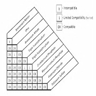
Zambian Standard ZS 357
|
PRESSED STEEL DOOR FRAMES – SPECIFICATION |
|
1. SCOPE |
|
This specification sets out the sizes, fittings and finish for pressed steel door frames. |
|
2. MATERIAL |
|
Pressed steel door frames shall be manufactured from good commercial quality mild steel of not less than 18 BG+ (1.2 mm). |
|
Note: +BG – Birmingham gauge |
|
3. SIZES |
|
The door frames shall be suitable for doors 45 mm nominal thickness and the door frames shall conform to the following door dimensions in Figures 1 to 3 and Table 1— |
|
TABLE 1—MODULAR AND OVERALL WIDTHS FOR DOOR FRAMES |
|
Door width |
Single door size |
Double door size |
|||
|
625 |
725 |
825 |
1125 |
1425 |
|
|
Overall |
695 |
795 |
895 |
1195 |
1495 |
|
Modular |
700 |
800 |
900 |
1200 |
1500 |
|
Note: |
|
1. All dimensions are in “mm”. |
|
The sizes include those for cupboard frames |
|
4. PROFILES |
|
4.1. Double rebated frames |
|
Steel door frames shall normally be double rebated and made in accordance with one of the three profiles 1 M, 1½ M or 2 M as shown in Figure 4. |
|
|
|
1. Single door frames |
|
|
|
2. Double door frames |
|
Note: |
|
1. Module and overall widths (See Table 1). |
|
2. All cupboard frames are for a 1 M wall and it is therefore not necessary to specify wall thickness when ordering. |
|
3. Modular height: 2600 mm |
|
Overall height: 2595 mm |
|
Figure 1 – Single door frames |
|
|
|
1. Plain door frames |
|
|
|
2. Door frames with fanlights beaded for fixed glazing (22F type) |
|
|
|
3. Door frames with fanlights beaded for timber sashes (24F type) |
|
Note: |
|
See Figure 1 for modular and overall heights |
|
Figure 2 – Double door frames |
|
|
|
1. Plain door frames |
|
|
|
Modular height: 2200 mm |
|
2. Door frames with fanlights beaded for fixed glazing (22F type) |
|
|
|
Modular height: 2400 mm |
|
3. Door frames with fanlights hinged for timber sashes (24F type) |
|
Figure 3-Cupboard frames |
|
|
|
½ M Profile double rebate 1½ M Profile single rebate |
|
|
|
|
|
½ M Profile double rebate 1½ Profile single rebate |
|
|
|
|
|
2 M Profile double rebate 2 M Profile single rebate. |
|
Note: |
|
Dimensions A: 12 mm, B: 48 mm, C: 32 mm, D: 12 mm |
|
Figure 4 – Frame profiles |
|
Each of the three profiles shall be supplied to suit doors of either hand. The profile sizes shall be as given in Table 2. |
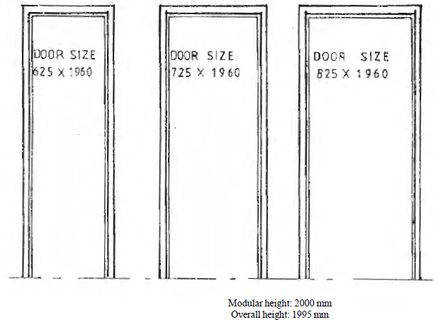
|
TABLE 2—DIMENSIONS FOR PROFILE SIZES |
||
|
Profile |
Overall size |
Thickness of wall |
|
1 M |
150 | 100 |
|
1½ M |
200 | 150 |
|
2 M |
250 | 200 |
|
All dimensions in millimetres. |
|
4.2. Single rebated frames |
|
Single rebated door frames and other profile sizes shall be matters for agreement between manufacturer and purchaser. |
|
5. CONSTRUCTION |
|
5.1. A door frame shall consist of a hinge jamb, lock jamb and head, the whole of which shall be welded together. |
|
5.2. Two base ties shall be applied to the frame. |
|
5.3. The corners shall be adequately reinforced with mild steel of thickness not less than 14 BG |
|
Note: |
|
(a) The corner plate shall be optional when corners are joined by continuous welding. |
|
(b) The welded frames shall be square and without twist. All welds on surfaces which will remain exposed after building-in shall be cleaned off flush. |
|
6. BASE TIES |
|
3.1. Base ties shall be of mild steel of a thickness not less than 18 BG (1.2 mm) and shall have an L-shaped section with a girth of not less than 25 mm. |
|
3.2. The base ties shall be positioned to allow for a 25 mm floor screed and finish as shown in Figures 5 and 6. |
|
7. FITTINGS |
|
Each door frame shall be provided with the following fittings— |
|
(a) Fixed lugs |
|
(i) There shall be three adjustable fixing lugs to each jamb. |
|
(ii) The lugs shall be at least 18 BG (1.2 mm) thick with a minimum outstand of 152 mm. |
|
(b) Hinges |
|
(i) One pair of 100 mm hinges shall be provided for each door jamb. The hinges shall have 5 knuckles and a removable pin, all made of mild steel. The minimum thickness of the hinge leaves shall be 14 BG (2 mm). The top of the upper hinge shall be positioned 127 mm from the inside of the head of the door and the bottom of the lower hinge shall be 1730 mm from the inside of the head of the door. |
|
(ii) When T-hinges are required for batten doors, the T-hinges shall have a minimum thickness of 14 BG (2 mm) and a minimum length of 305 mm. |
|
(c) Lock strike plate |
|
There shall be an adjustable lock strike plate of rust-proofed steel with a mortar guard, to accommodate locks or latches complying with ZS EN 12209. This lock strike plate shall be so placed that the distance from the inside of the rebate at the head to the centre line of the plate shall be 745 mm. |
|
(d) Shock absorbers |
|
(i) For side hung doors, there shall be at least two rubber buffers inserted in holes in the rebate and located at least 475 mm above and 940 mm below the centre line of the lock strike plate. |
|
(ii) For double doors, there shall be at least two rubber buffers inserted in holes in the rebate and located 152 mm on either side of the centre line of the frame at the top. |
|
8. FINISH |
|
5.1. Protective coating |
|
The door frames shall be cleaned of rust, scale and dirt and given a protective shop coat of paint complying with an appropriate standard on dipping primers. |
|
5.2. Alternative protective coatings |
|
The provision of other protective coatings shall as agreed between manufacturer and purchaser. If paint primers are specified they shall comply with ZS 201: 1994. |
|
9. MARKING |
|
Each door shall be marked with the manufacturer’s name or trade mark. |
APPENDIX A
INFORMATION TO BE SUPPLIED BY THE PURCHASER WHEN ORDERING
|
When ordering metal door frames, the purchaser should clearly indicate the following— |
|
(a) The handling of the door. This is determined by the side at which the door is hinged when standing on the pull side as shown in Figure 7. |
|
(b) Any special requirements such as single rebated frames or differing profiles (See clause 4.2.). |
|
(c) Type of lock or latch (See clause 7(c)). |
|
(d) For type 24F door frames, the requirement of the fanlight-hinged or fixed. |
|
Figure 5 – Threshold details |
|
|
|
Note: |
|
Tie bars welded to underside of jambs for use with 25 mm finished floor. |
|
Figure 6 – Application of doorframes to wall |
|
|
|
Note: |
|
Where wall thickness exceeds 2 M (nominal 200 mm) doorframes may be sited as desired on wall centre or abutting either inside or outside face. |
|
Figure 7 – Handling of doorframes |
|
|
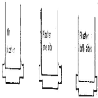
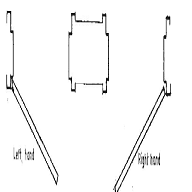
ANNEX A
(Informative)
CHEMICAL NAMES FOR PESTICIDES MENTIONED IN THIS STANDARD
|
Common name |
Chemical name |
|
Aldrin |
1,2,3,4,10,10-hexachloro-1,4,4a-5,8,8a-hexahydro-endo-1,4-exo- 5,8-dimethanonaphthalene |
|
Chlordane |
1,2,4,5,6,7,8,8-Octachloro-2,3,3a,4,7,7a-hexahydro-4,7-methanoindene |
|
2,4-D |
(2,4-dichlorophenoxy) acetic acid |
|
o,p’-DDT |
1,1,1-trichloro-2-(o-chlorophenyl) -2-(p-chlorophenyl)-ethane |
|
p,p’-DDT |
1,1,1-trichloro-2,2-bis(p-chlorophenyl) ethane |
|
Dieldrin |
1,2,3,4,10-10-hexachloro-exo-6,7-epoxy-,4a,5,6,-7,8,8a- octahydro-1,4-endo,exo-5,8-dimethanonaphthalene |
|
Endosulfan (Alpha and beta) |
6,7,8,9,10,10-hexachloro-exo-6,7-epoxy-4a,5,6,-7,8,8a-octahydro-1,4-endo, exo-5,8-dimethanonaphthalene |
|
Endrin |
1,2,3,4,10,10-hexachloro-6,7-epoxy -1,4,4a,5,6,7,8,8a-octahydro- endo-5,8-dimethanonaphthalene |
|
Heptachlor |
1,4,5,6,7,8,8-heptachloro-3a,4,7,7a-tetrahydro-4,7-methanoindene |
|
Hexachlorobenzene |
Same name |
|
Lindane (gamma BHC) |
1,2,3,4,5,6-a,a,e,e,e-hexachloro-cyclohexane |
|
Methoxychlor |
2,2,-bis(p-methoxyphenyl)-1,1,1-trichloroethane |
|
Toxaphene (camphechlor) |
Approximately C10H10Cl8 |
|
Note: |
|
1. “p,p’-DDT” is the pure technical form of DDT which is transformed into a family of closely related partial degradation and re-arrangement compounds (o,p’-DDT, DDD, DDE and others) in the environment. |
|
2. Toxaphene (camphechlor) is a mixture of chlorinated camphenes. |
Zambian Standard ZS 389
|
WHITE SUGAR – SPECIFICATION |
|
1. SCOPE |
|
This standard prescribes the requirements for white sugar derived from sugarcane or sugar beet intended for human consumption. |
|
2. NORMATIVE REFERENCES |
|
In this standard reference has been made to the following publications— |
|
Food and Drugs Regulations of Zambia; and |
|
ZS 033: Parts 1 to 5 – Labelling of prepackaged foods |
|
3. TYPES OF SUGAR |
|
White sugar shall be one of the following types classified according to its form— |
|
(a) granulated sugar; |
|
(b) mill white sugar (plantation white sugar); |
|
(c) brown sugar; |
|
(d) VHP (very high pol) sugar; |
|
(e) Mill white sugar (plantation white sugar); |
|
(f) refined sugar; |
|
(g) powdered sugar; |
|
(h) castor sugar; |
|
(i) icing sugar; or |
|
(j) sugar cubes. |
|
4. DEFINITIONS |
|
In this standard, unless the context otherwise requires— |
|
“white sugar” means purified crystallised sucrose (saccharose); |
|
“powdered sugar” means finely pulverised white sugar with or without the addition of an anti-caking agent; and |
|
“sugar cubes” means granulated sugar in the form of regular hexahedrons or tablets. |
|
5. COMPOSITIONAL REQUIREMENTS |
|
The composition of the various types of sugar shall be in accordance with the requirements given in Table 1. In addition to compositional specifications given in Table 1, sugar shall be fortified with vitamin A premix (see Appendix A). |
|
TABLE 1—COMPOSITIONAL REQUIREMENTS OF WHITE SUGAR |
|||||||
|
Characteristics |
Requirements of sugar |
||||||
|
|
Granulated |
Castor Sugar |
Powder (icing sugar) |
Sugar Cubes |
|||
|
Brown Sugar |
VHP Sugar |
Mill White Sugar |
Refined Sugar |
||||
|
Polarisation °S, min. |
98 |
99.3 |
99.5 |
99.8 |
99.78 |
99.78 |
99.7 |
|
Moisture %, max. (at 105° for 3 hours) |
0.05 |
0.05 |
0.05 |
0.05 |
0.04 |
0.04 |
0.20 |
|
Ash conductivity % m/m, max. |
0.10 |
0.10 |
0.10 |
0.04 |
0.04 |
0.04 |
0.04 |
|
Invert sugar % (m/m), max. |
0.10 |
0.10 |
0.10 |
0.04 |
0.04 |
0.04 |
0.04 |
|
Sulphur dioxide mg/kg, max. |
70 |
70 |
70 |
20 |
20 |
20 |
20 |
|
Colour (ICUMSA UNITS), max. |
2000 |
1500 |
650 |
100 |
100 |
100 |
100 |
|
Water-insoluble matters, mg/kg, max. |
60 |
60 |
60 |
60 |
— |
— |
— |
|
Arsenic, ppm, max. |
1 |
1 |
1 |
1 |
1 |
1 |
1 |
|
Lead, ppm, max. |
2 |
2 |
2 |
1 |
2 |
2 |
2 |
|
Copper, ppm, max. |
2 |
2 |
2 |
2 |
2 |
2 |
2 |
|
Vitamin A (as retinol), mg/kg, min. |
10 |
— |
10 |
10 |
— |
— |
— |
|
6. GENERAL REQUIREMENTS |
|
Sugar flavour shall be that which is characteristic of white sugar and shall be free from any foreign flavour and odour. The sugar shall be free of traces of pests, rodent and any other contaminants. No colouring matter or ultramarine shall be added to sugar. |
|
6.1. Permissible additives |
|
Anti-caking agents: |
|
(a) The following anti-caking agents may be added to powdered sugar singly or in combination— |
|
(i) Magnesium stearate or magnesium carbonate or magnesium trisilicate; |
|
(ii) Calcium triphosphate; |
|
(iii) Sodium – calcium – alumine – silicate; or |
|
(iv) Calcium silicate. |
|
However, starch shall not be— |
|
(i) present; and |
|
(ii) more than 1.5 per cent m/m. |
|
(b) When no other anti-caking agent is used in powdered sugar, starch can be used up to a maximum of 5 per cent m/m. |
|
6.2. Sieving requirements |
|
Not more than 4 per cent shall remain on a 1 mm aperture screen and not more than 8 per cent shall pass through a 0.180 mm (180µ) aperture screen. |
|
6.3. Hardness of cube sugar |
|
The pressure required to break each cube shall not be less than 10.5 kg/cm2. |
|
6.4. Microbiological requirements |
|
(a) Total count of organisms |
|
When tested in accordance with approved methods the total count of organisms shall not exceed 500 colonies per 1 g. |
|
(b) Yeast and moulds |
|
When tested in accordance with approved methods the total colony counts of yeasts and moulds shall not exceed 50 per 1 g. |
|
(c) Escherichia |
|
When tested in accordance with approved methods the product shall be free from Escherichia coli. |
|
7. PACKAGING AND MARKING |
|
7.1. Packing |
|
Sugar shall be packaged in a plastic film or paper bag made of non-toxic material whichever is applicable or any other suitable package. The material used to package sugar shall be clean and shall protect it from contamination and heat or light. |
|
7.2. Marking |
|
The label on the package shall, in addition to complying with the requirements of ZS 033: Parts 1 to 5, bear the following information in legible and indelible marking— |
|
(a) name and address of manufacturer, or the manufacturer’s registered trade mark; |
|
(b) type of sugar in accordance with clause 3; |
|
(c) for powdered sugar name of “anti-caking agent” shall be mentioned; |
|
(d) batch number; |
|
(e) net weight; |
|
(f) number of sugar cubes per pack; |
|
(g) retinol content; |
|
(h) the words “fortified with vitamin A” in bold letters; and |
|
(i) store in a cool dry place away from strong light. |
|
8. SAMPLING |
|
8.1. General requirements of sampling for inspection |
|
(a) In drawing, preparing, storing and handling samples, the following precautions and directions shall be observed. |
|
(b) Samples shall be taken in a protected place not exposed to damp air, dust or soot and sunlight or heat. |
|
(c) The sampling instruments shall be clean and dry when used. |
|
(d) Sampling for bacteriological purposes |
|
The sampling instruments and containers for samples shall be sterilised preferably by dry heat at 170°C for one hour before use. |
|
(e) Adequate precautions shall be taken to protect the samples, the material being sampled, the sampling instruments and the containers for samples from adventitious contamination. |
|
(f) The samples shall be placed in clean and dry moisture proof containers, which may be of glass, plastic or polyethylene materials. |
|
(g) Each sample container shall be sealed airtight after filling and marked with the name of the material date of sampling, batch number, and name of the manufacturer and other important particulars of the batch. |
|
(h) The sample shall be protected from light as far as practicable and shall be stored in a cool place. |
|
8.2. Scale of sampling |
|
(a) Lot |
|
All the containers of sugar in a single day’s production shall constitute a lot. |
|
(b) Gross sample |
|
A number of containers not less than the sample size indicated in Table 2 shall be selected at random from a lot for the purpose of drawing samples for test. This number of containers shall constitute the gross sample. |
|
(c) To ensure the randomness of selection, a random number table as agreed to between the purchaser and the supplier shall be used. In case such a table is not available the following procedure shall be used— |
|
Starting from any container count all the containers as 1, 2, 3,…. up to r and so on in one order, where ‘r’ is equal to the integral part of N/n, ‘N’ being the total number of containers in the lot and ‘n’ the number of containers to be selected, (see Table 2). Every ‘rth’ bag thus counted shall be withdrawn for sampling. |
|
(d) Containers stacked in pyramidical shape |
|
In case of bags stacked in a pyramidical shape, approximate equal number of bags shall be selected from all exposed sides of the lot so as to give the required number of sample bags. |
|
TABLE 2—SAMPLING SCALE |
|
|
Lot Size |
Sample Size |
|
(N) |
(n) |
|
2-15 |
2 |
|
16-50 |
3 |
|
51-150 |
5 |
|
151-500 |
8 |
|
501-3200 |
13 |
|
3201 and above |
20 |
|
8.3. Test samples and reference samples |
|
(a) Test samples |
|
Draw from the top bottom and middle of each container in the gross sample about 1.5 kg of the material with an appropriate sampling instrument. Mix thoroughly the material drawn from all the containers in the gross sample of that particular lot. Divide the composite sample with a suitable raffler into three approximately equal reduced samples. |
|
(b) These reduced samples shall constitute the test samples, each test sample being not less than 0.5 kg. |
|
(c) The test samples shall be transferred immediately to thoroughly clean dry and sterile glass containers that shall be sealed air tight and labelled with the particulars given in 8.1. (g). The inspecting authority shall take one test sample and the other shall be handed over or sent to the manufacturer or his representative. |
|
(d) Reference sample |
|
The third test sample, bearing the seals of the manufacturer and the inspecting authority shall constitute the reference sample to be used in case of dispute. It shall be kept at a place agreed to between the inspecting authority and the manufacturer, or in the absence of the manufacturer, the manufacturer’s representative. |
|
(e) Criterion for compliance |
|
If on testing the sample is found to conform to the requirements specified in the standard, the batch shall be accepted as complying to this standard. |
|
9. TEST METHODS |
|
White sugar shall be tested in accordance with approved methods of test for sugar including Honey. |
APPENDIX A
REQUIREMENTS FOR VITAMIN A FORTIFICANT PREMIX
|
A. 1. The retinol content shall not be less than 15 g/kg. |
|
A. 2. The vegetable oil |
|
A. 3. The antioxidant used shall be at levels adequate to prevent peroxidation and rancidity. |
|
A. 4. The vitamin A fortificant premix shall readily dissolve in water. |
|
A. 5. The packaging for vitamin A fortificant premix shall be of such quality and design as to protect the fortificant premix from contamination. |
|
A. 6. The following information shall appear on the label— |
|
(i) the date of manufacture; |
|
(ii) the retinol content; and |
|
(i) the words “VITAMIN A PREMIX NOT FOR DIRECT HUMAN CONSUMPTION” in letters half the size of the trade name. |
Zambian Standard ZS 394
|
AVIATION TURBINE FUEL – SPECIFICATION FOR JET A-1 |
|
1. SCOPE |
|
This Zambian Standard specifies requirements for Aviation Turbine Fuel, Jet A-1 in particular. |
|
2. NORMATIVE REFERENCES |
|
In this standard, reference has been made to the following methods— |
|
ZS 396 Sampling Petroleum Products Part 1: Manual Sampling of Liquid Hydrocarbons |
|
3. DEFINITIONS |
|
In this Standard, unless the context otherwise requires— |
|
“Additive” means a compound added to aviation turbine fuel to improve performance or storage stability. |
|
4. REQUIREMENTS |
|
4.1. General |
|
(i) The aviation turbine fuel shall be hydrocarbon oil derived from petroleum or fossil fuels. This does not preclude the incorporation of small amounts of additives intended to improve some aspects of performance. The product shall be free from inorganic acid and from quantities of grit, fibrous material and other foreign matter likely to interfere with the operation of normal equipment. |
|
(ii) When tested in accordance with the methods of test given in Table 1, aviation turbine fuel shall be in accordance with the limiting requirements given in the Table. |
|
(iii) On visual inspection at ambient temperature, the aviation turbine fuel shall be clear, bright and free from solid matter. |
|
4.2. Storage stability |
|
After conventional storage under normal conditions for a period of six months after the date of receipt, the aviation turbine fuel shall still comply with all the requirements of this standard (other than the requirements for potential gum content). |
|
5. PACKAGING AND MARKING |
|
5.1. Packaging |
|
The condition of the containers, rail tankers and road tank vehicles into which the aviation turbine fuel is filled shall be such as not to be detrimental to the quality of the fuel during normal transportation and storage. The containers shall be acceptably sealed and in addition shall conform to the Petroleum Act, Chapter 435 of the Laws of Zambia, and ZS 371. |
|
5.2. Marking |
|
The following information shall appear in legible and indelible marking on each container or in the case of aviation turbine fuel filled into bulk storage tanks, with the storage and consignment documents of each road tanker or rail wagon as stipulated in ZS 372— |
|
(i) the manufacturer’s name and address; |
|
(ii) the type of fuel as stipulated under UN Code; |
|
(iii) the hazards involved in handling and transportation; |
|
(iv) the Transport Emergency Card (Tremcard); |
|
(v) the volume in litres; and |
|
(vi) the batch/lot number. |
|
6. TEST METHODS |
|
For all characteristics, the test methods listed in column 4 of Table 1 shall apply. |
|
7. SAMPLING |
|
7.1. Sampling from storage tanks |
|
For the purpose of this Standard all sampling shall be carried out in accordance with the relevant procedures of ZS 396: Part 1 and, additionally, as detailed in 7.2. |
|
7.2. Sampling from fuel lines |
|
(a) Sampling cans of 5 litres and 1 litre capacity |
|
The construction of the cans shall comply with the appropriate safety requirements for cans that are to hold highly flammable material. They shall be provided with screw caps incorporating a petroleum resistant washer in good condition. A stock of cans shall be kept solely for the purpose of taking Aviation Turbine Fuel samples. |
|
(b) Preparation of cans |
|
New cans shall be rinsed with Aviation Turbine Fuel before being used to remove any residual traces of oil left during manufacturing operations, and then allowed to dry. Before use, all cans shall be checked to ensure that they are sound and free from leaks. |
|
(c) Sampling procedure |
|
From the pump nozzle, 5 litres of Aviation Turbine Fuel shall be drawn carefully into a cool 5 litres can using a clean dry funnel. Immediately afterwards, this sample shall be decanted carefully into the requisite number of one litre cans using a funnel, filling the cans within 15 mm of the brim. |
|
If more than 5 litres are needed, the operation shall be repeated immediately and before the pump has been used for any other purpose. The screw caps shall be tightened fully and the cans checked to ensure that there are no leaks. |
|
The sampling procedure shall not be carried out in direct sunlight. If carried out in direct sunlight, changes in fuel quality may occur. |
|
(d) Storage, labelling and transport |
|
(i) Samples shall be kept in a cool place although it is not necessary to keep them refrigerated. |
|
(ii) Full and legible information relating to the source of the sample shall be attached to the can in such a manner that it will not easily become detached subsequently. |
|
(iii) If required, the sample may be sealed and labeled to maintain its integrity. |
|
(iv) If the sample has to be sent to a laboratory by public transport, it will be necessary to comply with the general regulations covering transportation of flammable materials and with the requirements of the transport authority concerned. Information on the appropriate procedures and the type of packaging required should be obtained from the transport authority involved. |
|
TABLE 1—REQUIREMENTS FOR AVIATION TURBINE FUEL (JET A-1) |
|||
|
Characteristics |
Limit |
Requirement |
Test method |
|
COMPOSITION |
|
|
|
|
Acidity (mgKOH/g) |
Max |
0.015 |
ASTM D 3242, IP 354 |
|
Aromatics (% vol) |
Max |
22 |
ASTM D 1319, IP 156 |
|
Doctor Test1) |
|
Negative |
ASTM D 4952 |
|
Sulphur, Mercaptan (% m/m) |
Max |
0.003 |
ASTM D 3227 |
|
Sulphur, Total (% m/m) |
Max |
0.30 |
ASTM D 1266, D 1552, |
|
|
|
D 2622, D 4294 or 5453 |
|
|
Colour |
|
Report |
ASTM D 156 |
|
VOLATILITY |
|
|
|
|
Distillation Temperatures |
|
|
ASTM D 86 |
|
10% Recovered, Temperature, °C |
Max |
205 |
ASTM D 86 |
|
End Boiling Point, Temperature, °C |
Max |
300 |
ASTM D 86 |
|
Distillation Residue, (% vol) |
Max |
1.5 |
ASTM D 86 |
|
Distillation Loss, (% vol) |
Max |
1.5 |
ASTM D 86 |
|
Flash Point, (°C) |
Min |
38 |
ASTM D 56, D 3828 or |
|
Density at 15°C, (kg/m3) |
|
775 to 840 |
ASTM D 1298, D 4052 |
|
FLUIDITY |
|
|
|
|
Freezing Point, (°C) |
Max |
-47 |
ASTM D 2385, D 2386, |
|
Viscosity @ -20°C, (mm2/s) |
Max |
8 |
ASTM D 445 |
|
COMBUSTION |
|
|
|
|
Net Heat of Combustion, (MJ/kg) |
Min |
42.8 |
ASTM D 4529, D 3338 |
|
One of the following requirements shall be met— |
|
|
|
|
Luminometer Number |
Min |
45 |
ASTM D 1740 |
|
Smoke Point, (mm) |
Min |
25 |
ASTM D 1322 |
|
Smoke Point, (mm) and |
Min |
19 |
ASTM D 1322 |
|
Naphthalenes (% vol) |
Max |
3 |
ASTM D 1322 |
|
CORROSION |
|
|
|
|
Copper Strip, 2 hours at 100°C |
Max |
1 |
ASTM D 130 |
|
Ag Corrosion, 4 hours at 50°C |
Max |
2 |
IP 227 |
|
STABILITY |
|
|
|
|
Thermal: |
Max |
25 |
ASTM D 3241 |
|
Filter Pressure Drop, (mm Hg) |
Max |
3 |
ASTM D 3241 |
|
Tube Deposit less than |
|
|
|
|
CONTAMINANTS |
|
|
|
|
Existent Gum, (mg/100 ml) |
Max |
7 |
ASTM D 381 |
|
Water Reaction: |
|
|
|
|
Interface Rating |
Max |
1b |
ASTM D 1094 |
|
Water Separator Index |
Min |
70 |
ASTM D 2550 |
|
CONDUCTIVITY |
|
|
|
|
Electrical Conductivity, (pS/m) |
|
50-450 |
ASTM D 2624 |
|
ADDITIVES |
|
|
|
|
Anti-oxidant, (mg/l) |
|
|
|
|
Hydrotreated Fuels (Mandatory) |
Min |
17 |
ASTM D 2550 |
|
|
Max |
24 |
ASTM D 2550 |
|
Non Hydrotreated Fuels (Optional) |
Max |
24 |
ASTM D 2550 |
|
Metal Deactivator, (mg/l) |
Max |
5.7 |
ASTM D 2550 |
|
Static Dissipator (Mandatory) |
|
|
|
|
First Doping, (mg/l) |
Max |
3.0 |
ASTM D 2550 |
|
Cumulative Doping, (mg/l) |
Max |
5.0 |
ASTM D 2550 |
|
(1) A positive Doctor Test result will not stop a sample from qualifying providing that the Mercaptan Sulphur Result is within specification. |
Zambian Standard ZS 422-1
|
PENETRATION GRADE BITUMENS – SPECIFICATION |
|
1. SCOPE |
|
This Part of the ZS 422 specifies the requirements for penetration grade bitumens which are suitable for use in road construction in Zambia. The penetration grade bitumens are classified into a number of grades for each of which an appropriate designation and properties are specified. |
|
This Part of the standard does not cover bitumen emulsions, cut back bitumens or bitumen mixtures containing lake asphalt, coal tar or pitch; such materials are specified in a separate standard. Advice on handling and packaging, and on sampling and testing is given in the Appendices A and B. |
|
2. REFERENCES |
|
In this standard, reference has been made to the following methods— |
|
ZS 396 Sampling Petroleum Products – Part 1: Manual sampling of liquid hydrocarbons |
|
3. DEFINITIONS |
|
For the purpose of this standard, the following definition applies— |
|
3.1. Bitumen |
|
A viscous liquid, or solid, consisting essentially of hydrocarbons and their derivatives, which is soluble in trichloroethylene and is substantially non-volatile and softens gradually when heated. It is black or brown in colour and possesses waterproofing and adhesive properties. It is obtained by a refinery process from petroleum, and is found as a natural deposit or as a component of naturally occurring asphalt, in which it is associated with mineral matter. |
|
4. REQUIREMENTS |
|
4.1. General |
|
When tested in accordance with the methods of test given in Table 1, the penetration grade bitumen shall be within the limiting requirements given in the Table. |
|
Numbers representing the penetration range designate penetration grade of bitumen specified in this Part of the standard. Penetration grades are also referred to using the suffix ‘pen’. |
|
4.2. Storage stability |
|
(a) General |
|
Penetration grade bitumens require storage and handling plant equipped with heating facilities. However, this does depend on the cutback grade of the bitumen being handled. |
|
After conventional storage under normal conditions for a period of up to 6 months after the date of manufacture, the penetration grade bitumen shall comply with all the requirements of this standard. |
|
In the case of penetration grade bitumen that is stored for more than 6 months, the product shall comply with the requirements of Table 1. It shall comply with such other requirements as are agreed upon between the supplier and purchaser. |
|
(b) Marking |
|
The following information shall appear in legible and indelible marking on each container or in the case of products being transported in a road tank vehicle, in the storage and consignment documents— |
|
(i) the supplier’s name and address; |
|
(ii) the date of manufacture; |
|
(iii) the name of the product, e.g. 150/200 pen bitumen; |
|
(iv) the quantity in kg; |
|
(v) the batch/lot number; |
|
(vi) a statement on safety, health and environment. |
|
5. TEST METHODS |
|
For all characteristics, use the applicable methods listed in column 7 of Table 1. |
|
TABLE 1—REQUIREMENTS FOR PENETRATION GRADED BITUMENS |
||||||
|
1 |
2 |
3 |
4 |
5 |
6 |
7 |
|
|
|
GRADE |
|
|||
|
CHARACTERISTIC |
LIMIT |
40/50 pen |
60/70 pen |
80/100 pen |
150/200 pen |
TEST METHOD |
|
Penetration @ 25°C, 0.1 mm (100g/5s) |
Range |
40-50 |
60-70 |
80-100 |
150-200 |
ASTM D 5 |
|
Softening Point, °C |
Min |
49 |
46 |
41 |
36 |
IP 58 |
|
Max |
59 |
56 |
51 |
43 |
ASTM D 36 |
|
|
Ductility @ 25°C, mm |
Min |
1000 |
1000 |
1000 |
1000 |
ASTM D 113 |
|
Rolling Thin Film Oven Test Loss on Heating, % m/m |
Max |
0.8 |
1.0 |
1.0 |
1.4 |
ASTM D 2872 |
|
Retained Penetration of Residue, % of Original |
|
60 min |
55 min |
50 min |
45 min |
ASTM D 5 IP 49 |
|
Ductility of Residue @ 25°C, mm |
Min |
400 |
600 |
1000 |
1000 |
ASTM D 113 |
|
Solubility, Trichloroethylene, % m/m |
Min |
99.0 |
99.0 |
99.0 |
99.0 |
ASTM D 2042 IP 47 |
|
Viscosity @ 135°C, Pa.s |
Min |
0.27 |
0.22 |
0.15 |
0.12 |
ASTM D 4402 IP 319 |
APPENDIX A
(Normative)
HANDLING AND PACKAGING
|
A. 1. Handling and Packaging |
|
Penetration grade bitumens are normally supplied hot in bulk by road tanker, and handling procedures should be in accordance with the latest revision of the Institute of Petroleum Model Code of Safe Practice, Part 11, Bitumen Safety Code or the Bitumen Safety Handbook published by SABITA. Penetration grade bitumen may also be supplied in sealed drums and suppliers’ recommendations should be sought with regard to appropriate handling procedures. The condition of the containers and road tank vehicles into which the penetration grade bitumen is filled shall be such as not to be detrimental to the quality of the product during normal transportation and storage. The drums shall be sealed and shall conform to the Petroleum Act, Chapter 435 of the Laws of Zambia. |
APPENDIX B
(Normative)
SAMPLING AND TESTING
|
B. 1. Sampling Locations |
|
B. 1.1. For the purposes of this Zambian Standard all sampling shall be carried out in accordance with the relevant procedures of ZS 396. In addition, if it is desired to take a sample of penetration grade bitumen it may be taken from any of the following locations— |
|
(a) from the tanker, in the case of bulk delivery by road, immediately before discharge; |
|
(b) from the storage tank (or the feed pipe to the mixer) of a manufacturer of mixtures of bitumen and mineral matter, immediately before mixing; or |
|
(c) from the tank of a binder distributor used for surface dressing immediately before spraying. |
|
B. 2. Sampling Procedures |
|
When sampling penetration grade bitumen it is essential that the purchaser obtain a sample of not less than 5 kg, which represents the material supplied. The sample shall be immediately divided into three approximately equal sub-samples that shall be placed in clean and dry metal containers capable of being securely closed. Each sub-sample shall be clearly labelled with the names of the supplier and purchaser, details of the grades of penetration grade bitumen, time and date of sampling and identification of the sampling location. Samples should be retained for at least three months. |
|
It is essential that the purchaser use only one of the sub-samples for the purchaser’s own tests, the remaining two sub-samples being retained by the purchaser in case of dispute. |
|
Note: |
|
1. It is recommended that routine checking of penetration grade bitumen should be based on the penetration test and softening point in the case of grades covered in Table 1. Experience shows that checking other specified properties is only necessary when there are reasons to suspect the quality of the material. |
|
2. To ensure valid comparison between the test results of the purchaser and supplier, it is essential that both test the material within 7 days of taking the sample. |
Zambian Standard ZS 422-2
|
CUTBACK BITUMENS – SPECIFICATION |
|
1. SCOPE |
|
This Part of ZS 422 specifies the requirements for cutback bitumens which are suitable for use in road construction in Zambia. The cutback bitumens are classified into a number of grades for each of which an appropriate designation and properties are specified. |
|
This Part of the standard does not cover penetration grade bitumens, bitumen emulsions or bitumen mixtures containing lake asphalt, coal tar or pitch. Advice on handling and packaging, and on sampling and testing is given in the Appendices A and B. |
|
2. NORMATIVE REFERENCES |
|
In this standard, reference has been made to the following methods— |
|
ZS 396 Sampling Petroleum Products – Part 1: Manual sampling of liquid hydrocarbons |
|
3. DEFINITIONS |
|
For the purpose of this standard, the following definitions as well as those defined in Part 1 apply— |
|
“bitumen” means a viscous liquid, or solid, consisting essentially of hydrocarbons and their derivatives, which is soluble in trichloroethylene and is substantially non-volatile and softens gradually when heated and— |
|
(i) it is black or brown in colour and possesses waterproofing and adhesive properties; and |
|
(ii) it is obtained by a refinery process from petroleum, and is found as a natural deposit or as a component of naturally occurring asphalt, in which it is associated with mineral matter; and |
|
“cutback bitumen” means bitumen whose viscosity has been reduced by blending with a suitable volatile diluent. It is viscous at ambient temperatures and some grades will require heating before mixing and spraying. Cutback bitumen shall be homogenous, free from visible water and will not foam when heated to application temperature. |
|
4. REQUIREMENTS |
|
4.1. General |
|
When tested in accordance with the methods of test given in Table 1, the cutback bitumen shall be within the limiting requirements given in the Table. |
|
4.2. Storage stability |
|
(a) General |
|
Cutback bitumens require storage and handling plant equipped with heating facilities. However, this does depend on the cutback grade of the bitumen being handled. |
|
After conventional storage under normal conditions for a period of up to 6 months after the date of manufacture, the cutback bitumen shall comply with all the requirements of this standard. |
|
In the case of cutback bitumen that is stored for more than 6 months, the product shall comply with the requirements of Table 1. It shall comply with such other requirements as are agreed upon between the supplier and purchaser. |
|
(b) Marking |
|
The following information shall appear in legible and indelible marking on each container or in the case of cutback bitumen being transported in a road tank vehicle, in the storage and consignment documents— |
|
(i) the supplier’s name and address; |
|
(ii) the date of manufacture; |
|
(iii) the name of the product, e.g. MC 30 cutback bitumen; |
|
(iv) the quantity in kg; |
|
(v) the batch/lot number; and |
|
(vi) a statement on safety, health and environment. |
|
5. TEST METHODS |
|
For all characteristics, use the applicable methods listed in column 10 of Table 1. |
|
TABLE 1—REQUIREMENTS FOR CUTBACK BITUMENS1 |
|||||||||
|
1 |
2 |
3 |
4 |
5 |
6 |
7 |
8 |
9 |
10 |
|
|
GRADE |
|
|||||||
|
CHARACTERISTIC4 |
MC 30 |
MC 70 |
MC 800 |
MC 3000 |
TEST METHOD |
||||
|
|
Min |
Max |
Min |
Max |
Min |
Max |
Min |
Max |
|
|
Kinematic viscosity @ 60°C, cSt |
30 |
60 |
70 |
140 |
800 |
1600 |
3000 |
6000 |
ASTM D2170 |
|
Flash point, °C |
38 |
|
38 |
|
66 |
|
66 |
|
IP 113 or ASTM D 13101 |
|
Distillation, % by vol of total distillate to 360°C— |
|
|
|
|
|
|
|
|
|
|
to 190 °C |
0 |
15 |
— |
— |
— |
— |
— |
— |
IP 27 |
|
to 225 °C |
15 |
60 |
10 |
50 |
0 |
35 |
0 |
25 |
ASTM D |
|
to 260 °C |
50 |
85 |
40 |
80 |
10 |
60 |
0 |
40 |
402 |
|
to 316 °C |
80 |
100 |
80 |
95 |
50 |
90 |
35 |
85 |
|
|
Residue from distillation to 360°C, % vol of original sample |
50 |
— |
55 |
— |
75 |
— |
80 |
— |
IP 27 ASTM D 402 |
|
Penetration at 25°C on residue from distillation, 0.1 mm |
90 |
180 |
90 |
180 |
90 |
180 |
90 |
180 |
IP 49A STM D 5 |
|
Ductility on residue from distillation @ 25°C, mm |
1000 |
|
1000 |
|
1000 |
|
1000 |
|
ASTM D 113 |
|
Solubility Trichloroethylene, % m/m |
99.0 |
|
99.0 |
|
99.0 |
|
99.0 |
|
ASTM D 2042 |
|
Water, % volume |
|
0.2 |
|
0.2 |
|
0.2 |
|
0.2 |
ASTM D 95 |
|
1 All cutbacks shall be blended from pen 80 – 100 grade bitumen. |
|
2 Cutback bitumen shall be homogenous, free from visible water and will not foam when heated to application temperature. |
|
3 IP 113 and ASTM D 1310 are acceptable methods to be used to determine the flash point although cognisance should be taken of the diluent used to make the cutback bitumen as this will affect the accuracy of results obtained. |
APPENDIX A
(Normative)
HANDLING AND PACKAGING
|
A. 1. Handling and Packaging |
|
Cutback bitumens are normally supplied hot in bulk by road tanker. Handling procedures should be in accordance with the latest revision of the Institute of Petroleum Model Code of Safe Practice, Part 11, Bitumen Safety Code or the Bitumen Safety Handbook published by SABITA. Uncontrolled heating of cutback bitumens can lead to loss of volatile diluent and consequent non-compliance with the specification. |
|
Cutback bitumen may also be supplied in sealed drums and suppliers’ recommendations should be sought with regard to appropriate handling procedures. The condition of the containers and road tank vehicles into which the cutback bitumen is filled shall be such as not to be detrimental to the quality and quantity of the product during normal transportation and storage. The drums shall be sealed and shall conform to the Petroleum Act, Chapter 435 of the Laws of Zambia. |
APPENDIX B
(Normative)
SAMPLING AND TESTING
|
B.1. Sampling Locations |
|
B.1.1. For the purposes of this Zambian Standard all sampling shall be carried out in accordance with the relevant procedures of ZS 396. In addition, if it is desired to take a sample of cutback bitumen it may be taken from any of the following locations— |
|
(a) from the tanker, in the case of bulk delivery by road, immediately before discharge; |
|
(b) from the storage tank (or the feed pipe to the mixer) of a manufacturer of mixtures of bitumen and mineral matter, immediately before mixing; or |
|
(c) from the tank of a binder distributor used for surface dressing immediately before spraying. |
|
B.1.2. The procedures involved in handling the binder for surface dressing may lead to some loss of volatile constituents from the cutback bitumen without necessarily impairing the performance of the surface dressing. Where a sample of cutback bitumen has been taken from one of the locations listed in B.1.1 it shall be assumed that the viscosity requirements of the standard have been complied with provided the viscosity is within the following limits— |
|
Saybolt – Furol Viscosity Limits |
|
MC-30 – Furol Viscosity at 25°C – 75 to 150 sec |
|
MC-70 – Furol Viscosity at 50°C – 60 to 120 sec |
|
MC-800 – Furol Viscosity at 82.2°C – 100 to 200 sec |
|
MC-3000 – Furol Viscosity at 82.2°C – 300 to 600 sec |
|
B.2. Sampling Procedures |
|
When sampling cutback bitumen it is essential that the purchaser obtain a sample of not less than 5 kg, which represents the material supplied. The sample shall be immediately divided into three approximately equal sub-samples that shall be placed in clean and dry metal containers capable of being securely closed. Each sub-sample shall be clearly labelled with the names of the supplier and purchaser, details of the grades of cutback bitumen, time and date of sampling and identification of the sampling location. Samples should be retained for at least three months. |
|
It is essential that the purchaser use only one of the sub-samples for the purchaser’s own tests, with the remaining two sub-samples being retained by the purchaser in case of dispute. |
|
Note: |
|
1. It is recommended that routine checking of cutback bitumen should be based on the viscosity test in the case of grades covered in Table 1. Experience shows that checking other specified properties is only necessary when there are reasons to suspect the quality of the material. |
|
2. To ensure valid comparison between the test results of the purchaser and supplier, it is essential that both test samples are of the same age. |
SECOND SCHEDULE
[Paragraph 3]
|
1. |
ZS 063 |
Petroleum Jelly |
|
2. |
ZS 065 |
Pure Glycerine |
|
3. |
ZS 190 |
Drinking Water |
|
4. |
ZS 233 |
Crude Edible Vegetable Oils |
|
5. |
ZS 327 |
Blended (Physical Mixture) Fertilisers |
|
6. |
ZS 357 |
Pressed Steel Door Frames |
|
7. |
ZS 373 Part 1 |
Portable Fire Extinguishers |
|
8. |
ZS 373 Part 2 |
Portable Fire Extinguishers |
|
9. |
ZS 389 |
White Sugar |
|
10. |
ZS 394 |
Aviation Turbine Fuel |
|
11. |
ZS 422 Part 1 |
Penetration Grade Bitumens |
|
12. |
ZS 422 Part 2 |
Cutback Bitumens |