ELECTRICITY ACT: INDEX TO SUBSIDIARY LEGISLATION
Electricity Authority (Membership and Proceedings) Regulations
Electricity (Licensing) Regulations
Electricity (Acquisition of Land) Regulations
Electricity (Annual Returns) Regulations
Electricity (Private Undertakings’ Contracts) Regulations
Electricity (Registration of Private Undertakings) Regulations
Electricity (Inquiries into Accidents) Regulations
Electricity (Non-Standard Charges) Regulations
Electricity (Supply) Regulations
Electricity (Wiring) Regulations
Electricity (Inquiries into Disputes Procedure) Regulations
Electricity (Grid Code) Regulations
Electricity (Common Carrier) (Declaration) (Revocation) Order
ELECTRICITY AUTHORITY (MEMBERSHIP AND PROCEEDINGS) REGULATIONS
[Section 38]
Arrangement of Regulations
Regulation
1. Title
2. Interpretation
3. Application
4. Tenure of office
5. Member to declare interest
6. Publicity
7. Holding of meetings
8. Procedure at meetings
9. Minutes of meetings
[Regulations by the Minister]
GN 116 of 1956,
GN 34 of 1964,
SI 157 of 1965.
These Regulations may be cited as the Electricity Authority (Membership and Proceedings) Regulations.
In these Regulations, unless the context otherwise requires—
“authority” means the Electricity Council.
[Am by GN 34 of 1964.]
These Regulations shall apply to all members of the authority appointed, or deemed to have been appointed, under the provisions of the Act.
[Am by GN 34 of 1964; SI 157 of 1965.]
(1) Notwithstanding the conditions of his appointment, a member of the authority shall cease to be a member—
(a) on conviction under the provisions of the Act;
(b) on conviction by any court accompanied by sentence of imprisonment without the option of a fine;
(c) on being declared bankrupt;
(d) on being absent without the approval of the Chairman of the authority from four consecutive meetings of the authority; or
(e) when, in the opinion of the Minister, he is prevented by disability of body or mind from properly performing his functions as a member.
(2) A member of the authority who wishes to resign his membership shall give written intimation to the Minister of his wish to resign, and his resignation shall become effective only upon its acceptance by the Minister.
[Am by GN 34 of 1964; SI 157 of 1965.]
If a member of the authority has any direct interest, whether pecuniary or otherwise, in any business connected with the generation supply, purchase or sale of electricity or electrical appliances, he shall, at the time of his appointment as such member, disclose in writing to the Minister the fact and nature of his interest and shall make a similar disclosure from time to time of any acquisition of or any change in such interest and, unless the Minister otherwise directs, shall take no part in any deliberation or decision of the authority which relates to any such business.
[Am by SI 157 of 1965.]
No meeting of the authority shall be open to the press or to the public unless the authority shall otherwise decide in respect of any particular meeting or part thereof.
The authority shall normally meet on occasions decided by its Chairman and, whenever the Minister, the Chairman or not less than half of the appointed members of the authority require a meeting, the secretary of the authority shall, on being duly instructed, summon a meeting of the authority in such a manner that its members shall in normal circumstances receive notification of the meeting at least forty-eight hours before the time of the meeting.
[Am by SI 157 of 1965.]
(1) At every meeting of the authority, the Chairman appointed by the Minister shall, if present at the meeting, be Chairman of the meeting. If the Chairman appointed by the Minister is absent from the meeting, a member appointed by the Minister to act as Chairman or, failing such appointment by the Minister, elected by members present at the meeting, shall act as Chairman.
(2) All acts, matters or things authorised or required to be done by the authority shall be decided by resolution of a meeting at which a quorum is present.
(3) Every question for decision by the authority shall be decided by a majority of votes and, subject to the provisions of regulation 5, each member present at a meeting shall record his vote.
(4) If at any meeting of the authority the voting is equal on any matter for decision by the authority, the Chairman or member acting as such shall have a casting vote in addition to his deliberative vote.
(5) Not less than half the members of the authority shall constitute a quorum of any meeting of the authority.
(6) The Chairman or member acting as such shall declare the result of any decision of the authority and such declaration shall be final.
[Am by SI 157 of 1965.]
(1) Minutes shall be kept of the proceedings of every meeting of the authority. The minutes of the proceedings of a meeting of the authority shall be submitted at the next ensuing meeting and, if they are passed as correct. shall be signed by the Chairman or the member acting as such. and the signed record of the proceedings of a meeting shall be prima facie evidence in all Courts and circumstances that the proceedings as recorded were the proceedings of the meeting. Within 14 days of their being signed, the Chairman of the authority shall cause two copies of the signed minutes of each meeting to be sent to the Minister.
(2) Any member of the authority who has recorded a minority vote may have it recorded in the minutes that he dissented from any resolution and also, briefly, his reasons for such dissent.
(3) No motion or discussion shall be allowed on the minutes except as to their accuracy.
[Am by SI 157 of 1965.]
ELECTRICITY (LICENSING) REGULATIONS
[Section 38]
Arrangement of Regulations
Regulation
1. Title
2. Interpretation
3. Applications for licenses
4. Fees and particulars required
5. Advertisement of application
6. Notice of objection to grant of application
7. Hearing of application
8. Electricity Council to make recommendations to Minister
9. Application for review of license
10. Consumers to represent requisite consumption
11. Particulars required
12. Hearing of application
13. Electricity Council to make recommendations to Minister
14. Notification of licensee
15. Advertisement of proposed changes in license
16. Notice of objection
17. Hearing
18. Fees
[Regulations by the Minister]
Act 13 of 1994,
GN 117 of 1956,
GN 34 of 1964,
SI 157 of 1965.
These Regulations may be cited as the Electricity (Licensing) Regulations.
In these Regulations, unless the context otherwise requires—
“applicant” means a person who has applied or is applying, in accordance with the provisions of the Act, for the issue or review of a license, or an amended license, or for the cession, transfer, surrender or substitution of a license;
“licensee” means a person to whom a license has been issued, or has been deemed to have been issued, in accordance with the provisions of the Act.
An application for a license in terms of section 7 of the Act, an application for the review of a license in terms of paragraph (a), (b) or (c) of sub-section (1) of section 9 of the Act, and an application for the cession, transfer, surrender or substitution of a license in terms of sub-section (2) of section 9 of the Act may be made at any time and shall be addressed to the Secretary of the Electricity Council.
[Am by GN 34 of 1964.]
4. Fees and particulars required
(1) An application made in terms of section 7 of the Act or of paragraph (c) of sub-section (1) of section 9 of the Act or of sub-section (2) of section 9 of the Act shall be in Form 1 in the First Schedule and shall be accompanied by the appropriate fee as set out in the Second Schedule, and by a plan of the area of supply, and by particulars concerning the following matters where applicable—
(a) the situation and extent of the land which the applicant desires to use as sites for generating stations;
(b) if the ownership of the site is not vested in the applicant, the name and address of the owner;
(c) the source of the water supply and the usual quantity used or required;
(d) full particulars of land or any rights over land which it is proposed to acquire either by agreement or in accordance with the provisions of the Act;
(e) full particulars regarding the type of current, frequency and pressure to be used.
(f) full particulars of the proposed undertaking, including the maximum quantity of electricity which will normally be generated and the maximum installed capacity of the plant;
(g) the estimated cost of the undertaking;
(h) the point or points at which it is proposed to receive any supply of electricity in bulk;
(i) a schedule of charges; to be made to consumers;
(j) an estimate of the number of probable consumers within the area of supply and their estimated consumption of electricity;
(k) such further particulars and information as may be required by the Electricity Council or the Minister.
(2) In addition to the information required under sub-regulation (1), an applicant shall submit to the Electricity Council a draft advertisement containing the following particulars where appropriate—
(a) the description and address of the applicant;
(b) the object of the application;
(c) the proposed area of supply;
(d) the site and capacity of the proposed generating station;
(e) any further particulars which the Electricity Council may require to be included;
(f) a statement to the effect that plans and documents of the applicant’s proposals, together with details of the tariffs which it proposes to charge, are available for view by the public at a suitable and convenient place within the area of supply;
(g) a statement to the effect that any consumer or proposed consumer within the area covered by the application may object to the approval of the application in accordance with the provisions of regulation 6.
(3) An applicant who wishes to include in his area of supply all or part of the area under the jurisdiction of a local authority shall attach to his application a consent of such local authority or a decision of the Minister, as the case may be, given or made in terms of section 19 of the Act.
[Am by GN 34 of 1964.]
5. Advertisement of application
On receipt of an application made in terms of regulation 4, the Electricity Council shall, if satisfied that the applicant has complied with the provisions of the Act and of these Regulations and that the draft advertisement contains the necessary particulars, cause the advertisement to be inserted at the applicant’s expense in the Gazette and in a newspaper circulating in the proposed area of supply.
[Am by GN 34 of 1964.]
6. Notice of objection to grant of application
Any objection to the grant of an application which has been made in terms of regulation 4 shall be made in Form 2 in the First Schedule and shall be lodged with the Electricity Council within 21 days of the appearance in the Gazette of the relevant advertisement published in terms of regulation 5. Any objection made against the granting of an application shall contain the reasons for the objection and copies of any objections so made shall be lodged with the applicant.
[Am by GN 34 of 1964.]
The Electricity Council shall arrange for the hearing of an application made in terms of regulation 4, and any objection thereto made in terms of regulation 6, at a suitable time and place and shall give notice of such hearing to the applicant and to every objector not less than 10 days before the date fixed for the hearing:
Provided that, if there are more than twenty objectors to any one application, the Electricity Council may, by advertisement in a newspaper circulating in the area of supply covered by the application, give notice of the hearing of the application and objections thereto, and the appearance of such advertisement shall be regarded as the giving of notice to every objector in terms of this regulation
[Am by GN 34 of 1964.]
8. Electricity Council to make recommendations to Minister
When the Electricity Council has heard an application made in terms of regulation 4 and any objections thereto, it shall make its recommendations to the Minister on the application in accordance with the provisions of the Act, and its recommendations shall include the terms and conditions which should be described in the license.
9. Application for review of license
If a number of consumers or a local authority wish the Minister to review a license in terms of paragraph (a) or (b) of sub-section (1) of section 9 of the Act, they shall make application to the Electricity Council for the issue by the Minister of an amended license to the licensee concerned and shall send a copy of such application to such licensee. An application made in terms of this regulation shall be in Form 3 in the First Schedule.
[Am by GN 34 of 1964.]
10. Consumers to represent requisite consumption
(1) A number of consumers seeking the review of a license in terms of regulation 9 shall, at the time of making application, satisfy the Electricity Council that they represent the aggregate consumption required by paragraph (a) of sub-section (1) of section 9 of the Act, and the Electricity Council shall not consider any such application unless so satisfied.
(2) A licensee shall give to consumers who wish to seek the review of his license in terms of regulation 9 such information as may be necessary for those consumers to satisfy the Electricity Council in accordance with the provisions of sub-regulation (1).
[Am by GN 34 of 1964.]
An application made in terms of regulation 9 shall contain the following information—
(a) details of the amendments to the license which the applicants seek;
(b) the reasons for seeking the amendments;
(c) any other information which may be required by the Electricity Council.
[Am by GN 34 of 1964.]
On receipt of an application made in terms of regulation 9, the Electricity Council shall arrange for the hearing of the application at a suitable time and place and shall give an opportunity to representatives of the licensee and of any other applicant concerned to appear and to lead evidence in accordance with the provisions of sub-section (4) of section 9 of the Act.
[Am by GN 34 of 1964.]
13. Electricity Council to make recommendations to Minister
Having heard the application made in terms of regulation 9, the Electricity Council shall make its recommendations to the Minister as to the provisions and conditions to be included in the license.
[Am by GN 34 of 1964.]
If the Electricity Council proposes to recommend in terms of paragraph (d) of sub-section (1) of section 9 of the Act that the Minister shall review a license, it shall notify the licensee in writing of the alterations in the license which it proposes to recommend.
15. Advertisement of proposed changes in license
On receipt of a recommendation from the Electricity Council made in terms of paragraph (d) of sub-section (1) of section 9 of the Act, the Minister shall insert in the Gazette and in a newspaper circulating in the licensed area an advertisement setting out the changes proposed in the license, which shall include a statement to the effect that the licensee or any consumer or proposed consumer in the licensed area may lodge his objection with the Minister.
[Am by GN 34 of 1964.]
Any objection made in terms of regulation 15 against the approval by the Minister of a recommendation received from the Electricity Council in terms of paragraph (d) of sub-section (1) of section 9 of the Act shall be made in Form 2 in the First Schedule and shall be lodged with the Minister within 21 days of the appearance in the Gazette of the relevant advertisement published in terms of regulation 15. Any objection made against the approval of such a recommendation shall contain the reasons for the objections and copies of any objections so made shall be lodged with the Electricity Council and with the licensee.
[Am by GN 34 of 1964; SI 157 of 1965.]
Before making a decision on any recommendation of the Electricity Council made in terms of paragraph (d) of sub-section (1) of section 9 of the Act, the Minister shall, if so requested by any objector or by the Electricity Council, arrange for a hearing of the recommendation to be conducted, mutatis mutandis, in accordance with the provisions of regulation 12.
[Am by GN 34 of 1964.]
(1) An application made in terms of these Regulations shall be accompanied by the appropriate fees set out in the Second Schedule. If by any reason of inquiries into the affairs of the licensee additional expense is necessarily incurred by the Minister or the Electricity Council as the result of an application made in terms of these Regulations, the Minister may direct that all or part of the additional expense so incurred shall be paid by the applicant, so, however, that in the case of an application made in terms of paragraph (a) or (b) of sub-section (1) of section 9 of the Act, no additional expenses shall be payable by the applicant if as the result of that application an amendment to the license is made.
(2) The issue of a license or of an amended license, as the case may be, shall be conditional upon the payment of such amounts as may be payable by the applicant in terms of this regulation.
FIRST SCHEDULE
PRESCRIBED FORMS
FORM 1
[Regulation 4]
APPLICATION FOR THE ISSUE OF A LICENSE OR OF AN AMENDED LICENSE
To the Secretary,
Electricity Council.
Application is hereby made under the provisions of the Electricity Act—
*for the issue of a license
*for the issue of an amended license
*for the cession/transfer/surrender/substitution of a license in the following manner: …………
…………………………………………………………………………………………………………………………………
Attached hereto are the fees and statements of information and particulars as required in terms of the Regulations.
| Dated this | day of | 19 |
|
Signature of Applicant ………………………………. |
||
|
Address …………………………………… |
[Am by SI 157 of 1965.]
*Insert as appropriate.
FORM 2
[Regulations 6 and 16]
NOTICE OF OBJECTION TO THE ISSUE OF A LICENSE OR OF AN AMENDED LICENSE
To the Secretary,
*Electricity Council.
*The Permanent Secretary, Ministry of Power, Transport and Works.
Objection is hereby made to—
*the issue of a license
*the issue of an amended license.
*the cession/transfer/surrender/substitution of a license in respect of the ……………………
………………..…………………………………………………………………….. undertaking in the
terms contained in Gazette Notice No. …………………… of …………………… 20……….
The grounds for objection are ……………………………………………………………………
……………………………………………………………………………………………………..
……………………………………………………………………………………………………..
Dated this ………………………………………… day of ………………………………19…….
Signature of objector …………………………………
Address ………………………………………………..
[Am by SI 157 of 1965.]
*Insert as appropriate.
FORM 3
[Regulation 9]
APPLICATION FOR THE REVIEW OF A LICENSE
To the Secretary,
Electricity Council.
Application is hereby made to the Minister of Power, Transport and Works under the provisions of the Electricity Act, for the review of the license issued to …………… undertaking. Attached hereto are statements setting out details of the amendments to the license for which application is made, and setting out the reasons for seeking those amendments. Also attached are the fees payable with this application in terms of the Regulations.
Dated this ………… day of ………………………….. 20……..
Signature of Applicants ……………………………………………..
Addresses
…………………………………………………….. ………………………………………………….
……………………………………………………. …………………………………………………..
…………………………………………………… ……………………………………………………
[Am by SI 157 of 1965.]
SECOND SCHEDULE
[Regulation 18]
FEES TO ACCOMPANY APPLICATIONS IN CONNECTION WITH LICENSES FEE UNITS
| With an application for the issue of a license in accordance with the provisions of section 7 of the Act |
1500 |
| With an application for the review of a license in accordance with the provisions of paragraph (a) of sub-section (1) of section 9 of the Act |
300 |
| With an application for the review of a license in accordance with the provisions of paragraph (b) of sub-section (1) of section 9 of the Act |
600 |
| With an application for the review of a license in accordance with the provisions of paragraph (c) of sub-section (1) of section 9 of the Act |
400 |
| With an application for the cession or transfer of a license in accordance with the provisions of sub-section (2) of section 9 of the Act |
750 |
| With an application for the substitution of a license in accordance with the provisions of sub-section (2) of section 9 of the Act |
150 |
| With an application for the surrender of a license in accordance with the provisions of sub-section (2) of section 9 of the Act |
Nil |
[Am by Act 13 of 1994.]
ELECTRICITY (ACQUISITION OF LAND) REGULATIONS
[Section 38]
Arrangement of Regulations
Regulation
1. Title
2. Application for order for acquisition of land
[Regulations by the Minister]
GN 119 of 1956,
GN 34 of 1964,
GN 497 of 1964.
These Regulations may be cited as the Electricity (Acquisition of Land) Regulations.
2. Application for order for acquisition of land
An application for an order of the President for the acquisition of land in accordance with the provisions of section 22 of the Act shall be made to the Minister and shall set out—
(a) full particulars concerning the land which the authorised undertaker wishes to acquire;
(b) the reasons why the acquisition of the land in question is necessary for the purposes of the undertaking carried on by the authorised undertaker concerned;
(c) full particulars of the steps taken by the authorised undertaker to acquire the land by agreement with the owner; and
(d) any other particulars which the Minister may require.
[Am by GN 34 of 1964.]
ELECTRICITY (ANNUAL RETURNS) REGULATIONS
[Section 38]
Arrangement of Regulations
Regulation
1. Title
2. Interpretation
3. Submission of audited accounts to Electricity Council
4. Extension of period
5. Submission of returns to Electricity Council
6. Offences and penalties
[Regulations by the Minister]
Act 13 of 1994,
GN 120 of 1956,
GN 336 of 1962,
GN 34 of 1964.
These Regulations may be cited as the Electricity (Annual Returns) Regulations.
In these Regulations, unless the context otherwise requires—
“license” means a license issued, or deemed to have been issued, in accordance with the provisions of the Act;
“licensee” means a person to whom a license has been issued, or has been deemed to have been issued, in accordance with the provisions of the Act;
“scheduled prices” means a schedule of standard prices contained in a license.
3. Submission of audited accounts to Electricity Council
Every local authority and licensee shall, within six months of the close of the financial year of his undertaking, submit to the Electricity Council a copy of the audited balance sheet and accounts of his undertaking made up to the end of that financial year, together with any report of the auditor thereon:
Provided that, if a local authority or a licensee cannot within such period submit a copy of such audited balance sheet on the grounds that his accounts have not by that time been audited, he shall within six months of the end of such financial year submit a copy of his balance sheet and accounts certified by the accountant or treasurer responsible for those accounts and shall thereafter, as soon as they are available, submit copies of such audited accounts to the Electricity Council.
[Am by GN 34 of 1964.]
The Electricity Council may at its discretion permit a local authority or licensee to submit the returns required in accordance with the provisions of regulation 3 within a longer period than that laid down in that regulation.
5. Submission of returns to Electricity Council
Every local authority, licensee and every private undertaker who has contracted to supply electricity to any other person shall, within six months of the close of the financial year of his undertaking, submit to the Electricity Council a return setting out the following information with regard to his undertaking in respect of that financial year—
(a) the number of units generated;
(b) the number of consumers of various classes supplied;
(c) the number of units of electricity sold to each class;
(d) the prices charged;
(e) the following particulars relating to consumers who have been supplied with electricity at prices above or below the scheduled prices in accordance with the provisions of section 12 of the Act—
(i) the names of the consumers;
(ii) the amount of electricity supplied;
(iii) the prices charged for electricity;
(f) such other information as may be required by the Electricity Council.
[Am by GN 336 of 1962, 34 of 1964.]
Any person who contravenes or fails to comply with any provision of these Regulations with which it is his duty to comply shall be guilty of an offence and liable to a fine not exceeding one thousand five hundred penalty units.
[Am by Act 13 of 1994.]
ELECTRICITY (PRIVATE UNDERTAKINGS’ CONTRACTS) REGULATIONS
[Section 38]
Arrangement of Regulations
Regulation
1. Title
2. Submission of application
3. Particulars required
4. Recommendation of Electricity Council
5. Minister’s decision
6. Variation of contract
[Regulations by the Minister]
Act 13 of 1994,
GN 122 of 1956,
GN 34 of 1964.
These Regulations may be cited as the Electricity (Private Undertakings’ Contracts) Regulations.
Any person operating a private undertaking who, in accordance with the provisions of section 18 as read with sub-section (3) of section 39 of the Act, requires the consent of the Minister before contracting to supply electricity to any other person shall submit his application for the Minister’s consent to the Electricity Council.
[Am by GN 34 of 1964.]
Every application submitted to the Electricity Council in terms of regulation 2 shall include the following information—
(a) the type, pressure and quantity of current to be supplied to any other person under the proposed contract;
(b) the name and address of any person to whom it is proposed to supply electricity under the proposed contract;
(c) the price to be charged under the proposed contract;
(d) the provisions to be included in the proposed contract which relate to the termination of the agreement;
(e) a copy of the proposed contract; and
(f) any other information which the Electricity Council may require.
[Am by GN 34 of 1964.]
4. Recommendation of Electricity Council
Having considered the application, the Electricity Council shall submit to the Minister full details of the application and its recommendation thereon.
The Minister shall thereupon notify his decision to the private undertaker and, if the Minister gives his consent in terms of section 18 of the Act, the private undertaker shall lodge with the Electricity Council a copy of the signed contract.
[Am by GN 34 of 1964.]
The terms of a contract to which consent has been given by the Minister in terms of section 18 of the Act shall not be varied by a private undertaker without the consent of the Minister. If a private undertaker wishes to obtain the consent of the Minister to a variation of contract already approved by him, he shall submit an application in accordance with the provisions of regulation 3 and thereafter the Electricity Council and the Minister, respectively, shall deal with such application in accordance with the provisions of regulations 4 and 5.
[Am by GN 34 of 1964.]
ELECTRICITY (REGISTRATION OF PRIVATE UNDERTAKINGS) REGULATIONS
[Section 38]
Arrangement of Regulations
Regulation
1. Title
2. Particulars required in respect of existing undertakings
3. Particulars required in respect of new undertakings
4. Offences and penalties
[Regulations by the Minister]
Act 13 of 1994,
GN 123 of 1956.
These Regulations may be cited as the Electricity (Registration of Private Undertakings) Regulations.
2. Particulars required in respect of existing undertakings
Every person who, on the 27th April, 1956, operated a private undertaking the plant of which is rated at the site where it is installed at a capacity of one hundred or more kilowatts, whether for his own use or for supply to other persons, either wholly or partly, shall before the 1st October, 1956, submit to the Minister the following particulars in respect of the plant and installation—
(a) the name and address of the owner;
(b) the place where it is operated;
(c) the rated capacity, type of prime mover and current, systems, frequency and voltage; and
(d) any further relevant particulars required by the Minister.
3. Particulars required in respect of new undertakings
Every person who, after the 27th April, 1956, begins to operate a private undertaking as described in regulation 2 shall, within six months after so beginning to operate it, submit to the Minister the particulars set out in that regulation in respect of the plant and installation in question.
Any person who fails to comply with the provisions of these Regulations shall be guilty of an offence and shall be liable to a fine not exceeding seven hundred and fifty penalty units.
[Am by Act 13 of 1994.]
ELECTRICITY (INQUIRIES INTO ACCIDENTS) REGULATIONS
[Section 38]
Arrangement of Regulations
Regulation
1. Title
2. Interpretation
3. Appointment of boards of inquiry
4. Sittings and procedure
5. Chairman to have casting vote
6. Rights of entry and inspection
7. Offences and penalties
8. Legal representation
9. Remuneration of members
[Regulations by the Minister]
Act 13 of 1994,
GN 109 of 1957,
GN 34 of 1964,
GN 497 of 1964,
SI 157 of 1965.
These Regulations may be cited as the Electricity (Inquiries into Accidents) Regulations.
In these Regulations, unless the context otherwise requires—
“assessor” means an assessor appointed in terms of regulation 3(3);
“board” means a board of inquiry appointed in terms of regulation 3(1).
3. Appointment of boards of inquiry
(1) Whenever, in accordance with the provisions of section 35 of the Act, the Minister has ordered an inquiry to be held into the circumstances of an accident of which notice has been sent to him in terms of section 36 of the Act, he may appoint a board of inquiry which he may direct to answer such specific or general questions in relation to the accident as he may think proper in the public interest.
(2) A board shall consist of such members as the Minister may appoint and, if it consists of more than one member, the Minister shall nominate one of the members as the Chairman of the board.
(3) To assist a board, the Minister may appoint one or more assessors possessing special skill or knowledge relating to the questions to be investigated by the board.
(4) If any member of a board is, or becomes, unable or unwilling to act, or dies, the Minister may appoint another member in his place and, if such first mentioned member was Chairman, may nominate another member of the board as Chairman.
A board shall sit at such times and at such places as it may fix and shall hold its inquiry in public except in so far as it is of the opinion that it is necessary, for any of the reasons set out in Article 18(II) of the Constitution, that any part of the evidence given before it and any argument relating thereto should be heard in camera.
[Am by SI 157 of 1965.]
5. Chairman to have casting vote
If the members of a board are in any case equally divided on any question that arises during the proceedings of the board, the Chairman of the board shall have a second or casting vote.
6. Rights of entry and inspection
A board shall have power to inspect, or authorise any person to inspect, any electrical installations concerned in an accident which is the subject of its inquiry and to enter and inspect any premises of any undertaking, including any generating station or transmission line, where the entry and inspection thereof appears to the board to be necessary for the purpose of its inquiry.
If any person at any sitting of the board wilfully insults any member of the board or any assessor or wilfully interrupts the proceedings of the board or otherwise wilfully disturbs the peace or order of such proceedings, he shall be guilty of an offence and liable to a fine not exceeding one thousand five hundred penalty units or, in default of payment, to imprisonment for a period not exceeding six months.
[Am by Act 13 of 1994.]
Any person who is in any way implicated or concerned in the matter under inquiry by a board shall be entitled to be represented by a legal practitioner at the whole of the inquiry, and any other person who may consider it desirable that he should be so represented may, by leave of the board, be represented in the manner aforesaid.
(1) The Minister may direct what remuneration, if any, shall be paid to the members of a board and any assessor and may direct the payment of any other expenses attendant upon the carrying out of the board’s functions.
(2) Any sums payable in terms of this regulation shall be paid out of money appropriated for the purpose by Parliament.
[Am by GN 34 of 1964.]
ELECTRICITY (NON-STANDARD CHARGES) REGULATIONS
[Section 38]
Arrangement of Regulations
Regulation
1. Title
2. Interpretation
3. Particulars required
4. Submission of application
5. Notice of objection
6. Particulars of objection required
7. Further inquiries
8. Right to appear and lead evidence
[Regulations by the Minister]
GN 312 of 1959,
GN 34 of 1964.
These Regulations may be cited as the Electricity (Non-Standard Charges) Regulations.
In these Regulations, unless the context otherwise requires—
“applicant” means a consumer referred to in sub-section (4) of section 12 of the Act, and “application” shall be construed accordingly;
“the right to appear and lead evidence” means the right to appear and lead evidence conferred by the provisions of sub-section (6) of section 12 of the Act.
[Am by GN 34 of 1964.]
(1) An application shall be in writing.
(2) In an application the applicant shall state—
(a) the reasons for his application; and
(b) whether or not he wishes to exercise the right to appear and lead evidence.
The applicant shall submit his application to the Electricity Council forwarding at the same time a copy of his application to the licensee.
[Am by GN 34 of 1964.]
(1) If the licensee wishes to object to the application, he shall lodge a notice of his objection in writing with the Electricity Council within 30 days of the receipt by him of the copy of the application forwarding at the same time a copy of his objection to the applicant.
(2) A licensee who lodges a notice of objection referred to in sub-regulation (1) (hereinafter called an objector) shall state in the objection whether or not he wishes to exercise the right to appear and lead evidence.
6. Particulars of objection required
(1) The Electricity Council may require an applicant or licensee, whether or not he is an objector, to furnish such information which in its opinion is relevant to the application and any objection thereto as it may consider necessary for the proper consideration of the application and any objection thereto.
(2) The applicant and the licensee shall furnish such information as they may be required to furnish in terms of sub-regulation (1).
(3) The Electricity Council shall furnish the objector with copies of information obtained from the applicant and the applicant with copies of information obtained from the objector.
In addition to the power to require an applicant or licensee to furnish information conferred upon it by regulation 6, the Electricity Council may institute such inquiries and obtain such other information which in its opinion is relevant to the application and any objection thereto as it may consider necessary for the proper consideration of the application and any objection thereto.
8. Right to appear and lead evidence
If an applicant or an objector wishes to exercise the right to appear and lead evidence, the Electricity Council shall arrange a suitable time and place for that purpose and give notice to him and the other party, if any, not less than 10 days before the date so arranged.
ELECTRICITY (SUPPLY) REGULATIONS
Arrangement of Regulations
Regulation
PART I
PRELIMINARY
1. Title
2. Interpretation
PART II
ADMINISTRATION AND GENERAL
3. Chief Electrical Inspector and electrical inspectors
4. Application
5. Procedure as to settlement of disputes
6. Declared method of supply to new consumers
7. Declared method of supply to existing consumers
8. Undertaker to provide constant supply
9. Undertaker may lessen or discontinue supply
10. Undertaker shall not permanently connect
11. Undertaker not compelled to commence supply
12. Discontinuance of supply
13. Disconnection of works in certain circumstances
14. Connection of system with earth
15. Protection of telegraphs
16. Access to undertaker’s works
17. Guidance and instructions
18. Inspections and tests
19. Availability of Regulations
PART III
CONSTRUCTION OF UNDERTAKERS’ WORKS
20. Design and protection of works
21. Switchgear
22. Fuses
23. Automatic circuit-breakers
24. Joints and connections
25. Isolating and protective devices
26. Switchboards
27. Buildings for electrical purposes
28. Outdoor substations
29. Earthing of metal-work
30. Earthing of consumer’s installation
31. Earth electrodes
32. Leakage to earth
33. Arc suppression coils
34. Service lines on consumer’s premises
PART IV
CABLES
35. Construction and installation of cables
36. Metallic protection for high-voltage cables
37. Identification and testing
PART V
OVERHEAD LINES
38. Application of Part V
39. Constructional requirements
40. Materials
41. Minimum heights and clearances
42. Overhead lines crossing railway tracks
43. Different voltages in proximity
44. Loading conditions and factors of safety
45. Periodic testing and inspecting
46. Warning notices
47. Unauthorised climbing
PART VI
PROTECTIVE MULTIPLE EARTHING
48. Description
49. Consent
50. Limitations
51. Connections at transformer
52. Use of cables
53. Use of overhead lines
54. Use of cables and overhead lines
55. Overall resistance
56. Neutral to be unbroken
57. Consumer’s earthing
PART VII
STANDARDS OF MEASUREMENT
58. Fundamental electrical units
59. Derived electrical units of energy
60. Measurement of electricity
PART VIII
OFFENCES AND PENALTIES
61. Offences and penalties
[Regulations by the Minister]
Act 13 of 1994,
GN 404 of 1961,
GN 34 of 1964,
SI 157 of 1965.
PART I
PRELIMINARY
These Regulations may be cited as the Electricity (Supply) Regulations.
In these Regulations, unless the context otherwise requires—
“bulk supply” means a supply of electricity to be used for the purposes of redistribution;
“cable” means an insulated conductor or an assemblage of such conductors enclosed within a common sheathing;
“conductor” means a bar, tube, wire or line used for conducting electricity;
“consumer” means a person, other than an undertaker, who is supplied or who has made application to be supplied with electricity by an undertaker;
“consumer’s installation” means the consumer’s electrical wiring together with any electricity consuming device connected with such installation;
“dead” means at or about earth potential or zero voltage and not connected to a live conductor or live part of a system;
“earthed” and “connected with earth” mean connected with the general mass of earth in such manner as will ensure at all times an immediate and efficient discharge of electricity, and cognate expressions shall be construed accordingly;
“electric line” means a cable, overhead line or other means used or intended to be used for the purpose of conveying, transmitting or distributing electricity together with any casing, coating, covering, tube, pipe or insulator enclosing, surrounding or supporting the same, or any part thereof, or any apparatus connected therewith for the purpose of conveying, transmitting or distributing electricity;
“electrical inspector” means a person referred to in regulation 3;
“failing load” means a load on a support which, if exceeded, will result in the conductor not being supported in accordance with these Regulations;
“form” means the appropriate form prescribed in the First Schedule;
“high voltage” means normal operating voltage exceeding 650 volts;
“insulated conductor” means a conductor covered with insulation suitable for the normal operating voltage;
“insulation” means non-conducting material enclosing, surrounding, or supporting a conductor or any part thereof;
“line conductor” means a conductor of an overhead line;
“Lines Protection Regulations” means the General Post Office (Lines Protection) Regulations;
“live” means electrically charged;
“low voltage” means normal operating voltage exceeding 30 volts alternating current or 50 volts direct current but not exceeding 250 volts;
“main” means an electric line through which electricity may be supplied or is intended to be supplied by the undertaker to a service line;
“medium voltage” means normal operating voltage exceeding 250 volts but not exceeding 650 volts;
“metal armouring” means metal wire or metal tape completely covering a cable and manufactured as an integral part of the cable;
“metal sheathing” means a continuous and watertight metal sleeve surrounding a cable manufactured as an integral part of the cable;
“metal-work” means any metal-work other than—
(a) a conductor and its associated live parts; or
(b) an earth conductor;
“overhead line” means a conductor erected above ground and in the open air and includes any pole-mounted substation associated therewith;
“pole-mounted substation” means transformer equipment, high-voltage switchgear or high-voltage apparatus mounted on a support and associated with the operation and control of an overhead line;
“service line” means an electric line through which electricity may be supplied or is intended to be supplied by the undertaker to a consumer either from a main or directly from the premises of the undertaker;
“supply terminals” means the end of a service line at which the supply of electricity is delivered from such line to the consumer;
“support” means a structure or pole for supporting an overhead line and includes any stay or strut associated therewith;
“telegraph” or “telegraph line” means a telegraph or telegraph line as defined in section 2 of the Posts and Telegraphs Act;
“undertaker” does not include a person operating a plant which is rated at the site where it is installed at a capacity of less than one hundred kilowatts for the generation and supply of electricity solely for his own use or for use on his own premises;
“voltage” means the electro-motive force existing between any pair of live conductors forming part of a common supply of electricity or between any part of either of such conductors and earth and, in the case of alternating current, means the virtual voltage or root-mean-square value as determined by the square-root of the mean or average value of the squares of the instantaneous values of the voltage during one complete cycle;
“Wiring Regulations” means the Electricity (Wiring) Regulations.
PART II
ADMINISTRATION AND GENERAL
3. Chief Electrical Inspector and electrical inspectors
(1) There shall be a Chief Electrical Inspector and such electrical inspectors as may be considered necessary.
(2) Subject to the directions of the Minister, the Chief Electrical Inspector shall administer these Regulations.
(3) No person shall be appointed—
(a) as the Chief Electrical Inspector unless he is a Chartered Electrical Engineer with experience in the electricity supply industry to the satisfaction of the Minister; or
(b) as an electrical inspector unless he has had experience in the electricity supply industry to the satisfaction of the Minister.
[Am by GN 34 of 1964.]
(1) Subject to the provisions of sub-regulations (2) and (3), these Regulations shall apply to every undertaker.
(2) Parts III, IV and V shall not apply—
(a) to the construction, installation, quality, alteration, operation, control, protection, inspection and testing of the parts of an undertaker’s works which are used exclusively for mining or factory purposes at a mine or factory where such parts comply with the electrical provisions of any written law or regulations relating to such construction, installation, quality, alteration, operation, control, protection, inspection and testing at a mine or factory;
(b) to the construction, installation and quality of an undertaker’s works, or any part thereof, installed or erected, or for the installation or erection of which an agreement was entered into, before the commencement of Part III or Parts IV and V, as the case may be, until such works or part thereof are altered or replaced after such commencement.
(3) Regulation 27 shall not apply to the construction of a building by an undertaker for the accommodation, of any of his works where such building complies with any written law or by-law relating to its construction.
[Am by GN 34 of 1964; SI 157 of 1965.]
5. Procedure as to settlement of disputes
(1) Where an undertaker in pursuance of these Regulations declines—
(a) to connect a consumer’s installation or any part thereof with the undertaker’s electric lines; or
(b) to give or continue to give a supply of electricity; or
(c) to recommence a supply of electricity after it has been disconnected;
the undertaker shall give notice to the consumer On Form No 1 stating the reasons for so declining.
(2) Where a difference arises—
(a) between a consumer and an undertaker—
(i) with reference to a notice given in terms of sub-regulation (1) or (2) of regulation 11; or
(ii) with reference to a consumer’s installation to which the provisions of regulation 10 apply; or
(iii) concerning the measurement of electricity; or
(iv) in the application of these Regulations generally; or
(b) between one undertaker and another in connection with these Regulations;
the Minister may order an inquiry to be held in terms of section 35 of the Act.
6. Declared method of supply to new consumers
(1) Subject to the provisions of sub-regulation (4), before giving a supply of electricity to a consumer the undertaker shall declare in writing to that consumer the standard type of current and number of phases, the standard frequency and the standard voltage at which the undertaker proposes to deliver the electricity to the supply terminals.
(2) Subject to the provisions of sub-regulation (4), for the purposes of sub-regulation (1)—
(a) the standard type of current and number of phases shall be alternating current, one or three phases;
(b) the standard frequency shall be 50 cycles per second;
(c) the standard voltage shall be—
(i) 225 volts phase to neutral for a single-phase supply; or
(ii) 390 volts phase to phase for a three-phase supply.
(3) Subject to the provisions of sub-regulation (4), the standards referred to in paragraphs (a), (b) and (c) of sub-regulation (2) shall be constantly maintained subject to a permissible variation—
(a) of frequency, between a lower limit of 48.75 cycles per second and an upper limit of 51.25 cycles per second;
(b) of voltage—
(i) between a lower limit of 210 volts phase to neutral and an upper limit of 240 volts phase to neutral in the case of a single-phase supply;
(ii) between a lower limit of 365 volts phase to phase and an upper limit of 415 volts phase to phase in the case of a three-phase supply.
(4) Departures from the provisions of sub-regulation (1), (2) or (3) may be made by an undertaker—
(a) by agreement with a consumer to whom it is intended to give an individual supply of electricity from a distributing main to be used solely for the purposes of that one consumer; or
(b) by agreement with each consumer in a group of consumers to whom it is intended to give a supply of electricity from a common distributing main for the group; or
(c) in giving a supply of electricity at high voltage in terms of a published tariff; or
(d) in giving a special supply of electricity for purposes outside the terms of the undertaker’s published tariffs:
Provided that a departure made in terms of this sub-regulation to a consumer shall not adversely affect any other consumer.
(5) Before giving a supply of electricity to a consumer in accordance with the provisions of sub-regulation (4), the undertaker shall declare in writing to that consumer the type of current and, if alternating current, the number of phases and frequency and the voltage at which the undertaker proposes to deliver the electricity to the supply terminals.
(6) Where a supply of electricity is given in terms of sub-regulation (4), it shall be constantly maintained as declared in sub-regulation (5) subject to a permissible variation—
(a) of frequency, if alternating current, not exceeding two and one-half per centum above or below the declared frequency;
(b) of voltage, not exceeding 10 per centum above or below the declared voltage except where the special agreement for the supply stipulates a different permissible voltage variation.
(7) Before giving a bulk supply of electricity to another undertaker for redistribution, the supplying undertaker shall declare in writing to the receiving undertaker the type of current and, if alternating current, the number of phases and frequency and the voltage at which it is proposed to deliver the electricity:
Provided that where the bulk supply is alternating current intended for redistribution to consumers to whom the provisions of sub-regulations (1), (2) and (3) apply—
(i) the declared frequency shall be fifty cycles per second;
(ii) such frequency shall be constantly maintained subject to the permissible variations set out in paragraph (a) of sub-regulation (3);
(iii) any limits to voltage variation agreed between the two undertakers shall be such as will not adversely affect any consumer in respect of the provisions of paragraph (b) of sub-regulation (3).
(8) Except for causes beyond the control of the undertaker and subject to the provisions of regulation 8—
(a) any permissible variation provided for in this regulation to a declared frequency of 50 cycles per second shall be compensatorily adjusted to give a mean frequency of 50 cycles per second as far as practicable in each continuous period of 24 hours;
(b) any permissible variation provided for in this regulation to a declared voltage may be exceeded during control operations on the system for a period not longer than 10 consecutive minutes.
(9) Subject to the terms and conditions of a contract of supply between an undertaker and a consumer entered into on or after the 1st December, 1961, nothing in this regulation provided shall prevent such undertaker and consumer by agreement terminating the contract of supply made in terms of sub-regulations (1), (2) and (3) and substituting therefor a new contract of supply made in terms of sub-regulations (4), (5) and (6), or vice versa, provided that no other consumer is adversely affected thereby.
7. Declared method of supply to existing consumers
(1) Where an undertaker continues to give a supply of electricity to a consumer on and after the 1st December, 1961, in accordance with a contract or verbal agreement to supply existing at but made before such date, the provisions of this regulation shall apply to the declared method of supply.
(2) The supply of electricity under an existing contract or verbal agreement which requires the undertaker to deliver the electricity to the supply terminals—
(a) as alternating current, one or three phases;
(b) at a frequency of fifty cycles per second;
(c) at a voltage of—
(i) 220 volts or 230 volts phase to neutral for a single-phase supply; or
(ii) 380 volts or 400 volts phase to phase for a three-phase supply;
shall, in the absence of an agreement to the contrary, be constantly maintained subject to the permissible variations set out in sub-regulation (4) and shall continue to be the declared method of supply for such period of time as is determined by sub-regulation (6).
(3) The supply of electricity under an existing contract or verbal agreement which requires the undertaker to deliver the electricity to the supply terminals at values differing from those set out in paragraphs (a), (b) and (c) of sub-regulation (2) shall be constantly maintained subject to the permissible variations set out in sub-regulation (5) and shall continue to be the declared method of supply for such period as is determined in the manner set out in sub-regulation (7).
(4) There shall be a permissible variation for the purposes of sub-regulation (2)—
(a) of frequency, between a lower limit of 48.75 cycles per second and an upper limit of 51.25 cycles per second;
(b) of voltage—
(i) between a lower limit of 210 volts phase to neutral and an upper limit of 240 volts phase to neutral in the case of either a 220 volts or a 230 volts single-phase supply;
(ii) between a lower limit of 365 volts phase to phase and an upper limit of 415 volts phase to phase in the case of either a 380 volts or 400 volts three-phase supply.
(5) Except where the existing contract or verbal agreement to supply includes specific terms for permissible variations which shall prevail during the continuation of the contract or verbal agreement, there shall be a permissible variation for the purposes of sub-regulation (3)—
(a) of frequency, if alternating current, not exceeding two and one-half per centum above or below the normal frequency;
(b) of low voltage or medium voltage, not exceeding six per centum above or below the normal voltage;
(c) of high voltage, not exceeding 10 per centum above or below the normal voltage.
(6) The declared method of supply to a consumer set out in sub-regulation (2) shall continue in force until—
(a) termination of the existing contract or verbal agreement to supply or permanent discontinuance of supply to that consumer; or
(b) there is an agreement made between the undertaker and the consumer to terminate the existing contract or verbal agreement to supply and to substitute therefor a new contract of supply which shall be subject to the provisions of regulation 6; or
(c) the 1st December, 1966;
whichever is the earliest.
(7) The declared method of supply to a consumer set out in sub-regulation (3) shall continue in force until—
(a) termination of the existing contract or verbal agreement to supply or permanent discontinuance of supply to that consumer; or
(b) there is an agreement made between the undertaker and the consumer to terminate the existing contract or verbal agreement to supply and to substitute therefor a new contract of supply which shall be subject to the provisions of regulation 6;
whichever is the earlier.
(8) Before the date referred to in paragraph (c) of sub-regulation (6), except where there has been a prior termination of the existing contract or verbal agreement in terms of paragraph (a) or (b) of that sub-regulation, the undertaker—
(a) shall serve on each consumer affected by the provisions of that sub-regulation a notice declaring the new method of supply; or
(b) shall declare the new method by publication in a newspaper circulating in the area affected.
(9) On and after the date referred to in paragraph (c) of sub-regulation (6), except where there has been a prior termination of the existing contract or verbal agreement in terms of paragraph (a) or (b) of that sub-regulation, each consumer affected by the provisions of that sub-regulation and of sub-regulation (8) shall be deemed to be a consumer to whom the provisions of regulation 6 apply:
Provided that the permissible variation referred to in sub-regulation (3) of regulation 6 shall only apply in the absence of an agreement to the contrary.
(10) Subject to any terms of a contract of supply between the undertaker and another undertaker existing at but made before the 1st December, 1961, the provisions of sub-regulation (7) of regulation 6 shall apply, mutatis mutandis, to such existing contract during its continuation.
(11) The provisions of sub-regulation (8) of regulation 6 shall apply, mutatis mutandis, to permissible variations of frequency and voltages referred to in this regulation.
8. Undertaker to provide constant supply except by agreement in writing between an undertaker and a consumer provided that no other consumer is adversely affected thereby.
(1) Subject to the provisions of sub-regulation (2), from the time an undertaker begins to supply electricity through a distributing main or service line, he shall maintain a supply of electricity in terms of the agreement sufficient for the use of each consumer entitled for the time being to be supplied therefrom and that supply shall be constantly maintained to each consumer without change—
(a) in the declared method of supply set out in regulation 6 or 7 except as provided for therein;
(b) in the relationship between the neutral conductor and earth or between the neutral conductor and any phase conductor;
(c) in the phase rotation.
(2) An undertaker shall not lessen or discontinue a supply which is required to be constantly maintained in terms of sub-regulation (1) except—
(a) where permitted by the provisions of section 14 of the Act; or
(b) where required or permitted by the provisions of these Regulations.
9. Undertaker may lessen or discontinue supply
(1) An undertaker may temporarily lessen or discontinue a supply of electricity referred to in regulation 8—
(a) without prior notice to a consumer likely to be affected—
(i) where such action is necessary to prevent danger to life or damage to property; or
(ii) in an emergency, from whatsoever cause arising including any political cause, to ensure the proper working of the undertaking or of any other undertaking with which it is interconnected; or
(iii) by the automatic operation of a protective device installed to disconnect a supply of electricity in fault conditions; or
(iv) by the automatic or hand operation of a device installed to disconnect a supply of electricity in terms of the conditions or agreement to supply; or
(b) on giving not less than 24 hours’ notice—
(i) for the purposes of making alterations or additions to a system; or
(ii) for normal maintenance work; or
(iii) for testing a device referred to in sub-paragraph (iii) or (iv) of paragraph (a).
(2) The normal supply of electricity shall be resumed as soon as it is safe and expedient to do so after a temporary lessening or discontinuance referred to in sub-regulation (1).
(3) The notice required in terms of paragraph (b) of sub-regulation (1) shall state the period during which the supply may be affected and shall—
(a) be served in accordance with the provisions of section 37 of the Act; or
(b) be published in a newspaper circulating in the area affected.
(4) In temporarily lessening or discontinuing a supply of electricity in the circumstances set out in sub-paragraph (ii) of paragraph (a) of sub-regulation (1), the undertaker, unless all his consumers are affected thereby, may select which consumer or group of consumers shall have a supply so lessened or discontinued.
10. Undertaker shall not permanently connect
(1) An undertaker shall not permanently connect a consumer’s installation or part thereof with his low-voltage or medium-voltage electric lines if he or a person authorised by him is aware that the connection, if made, would cause a dangerous leakage of electricity from such installation or part thereof.
(2) An undertaker shall not permanently connect a consumer’s installation or part thereof with his high-voltage electric lines unless he or a person authorised by him is satisfied that the high-voltage portion of the consumer’s installation is of a standard of construction and safety not less than that required for an undertaker’s high-voltage works in terms of these Regulations.
(3) Where an undertaker does not permanently connect a consumer’s installation or part thereof under the provisions of sub-regulation (1) or (2), he shall give immediate notice to the consumer on Form No. 1 stating the reasons therefor.
11. Undertaker not compelled to commence supply
(1) An undertaker may refuse to give or, subject to the provisions of regulation 12, to continue to give a supply of electricity to a consumer’s installation or part thereof unless the undertaker or a person authorised by him is reasonably satisfied that such installation or part thereof—
(a) complies with the Wiring Regulations; or
(b) in the case of an installation used for mining purposes, has been subjected to an insulation resistance test and the undertaker or a person authorised by him is satisfied with the result of such test; or
(c) had been connected with the undertaker’s lines and had been supplied with electricity before the 1st December, 1961, and—
(i) such installation had continued to function satisfactorily up to the present time;
(ii) the installation is to be or is being continued in use only within the limits of the maximum power for which it was originally intended;
(iii) there are no grounds for supposing that the installation will fail to continue to function satisfactorily for a further reasonable period without risk of danger.
(2) Where an undertaker does not give or continue to give a supply of electricity under the provisions of sub-regulation (1), he shall give immediate notice to the consumer on Form No. 1 stating the reasons therefor.
(1) Where an undertaker in giving a supply of electricity has reasonable grounds for supposing that a consumer’s installation or part thereof—
(a) does not comply with the provisions of sub-regulation (1) or (2) of regulation 10; or
(b) does not comply with the provisions of paragraph (a), (b) or (c) of sub-regulation (1) of regulation 11; or
(c) is being operated in such a way as to endanger any person or as to cause or as is likely to cause damage to property; or
(d) is interfering with or is likely to interfere with the efficient supply of electricity to any other consumer;
the provisions of this regulation shall apply.
(2) Where the undertaker is satisfied that immediate action is justified in the consumer’s interests or in the public interest as a result of any of the circumstances set out in paragraphs (a), (b), (c) and (d) of sub-regulation (1), he may forthwith discontinue the supply of electricity without prior notice.
(3) Where an undertaker has discontinued a supply of electricity in terms of sub-regulation (2), he shall give immediate notice to the consumer on Form No. 1 stating the reasons therefor.
(4) Where the undertaker is not satisfied that immediate action is justified in terms of sub-regulation (2), he may arrange to make a detailed inspection and test of the consumer’s installation either—
(a) by verbal agreement with the consumer; or
(b) where verbal agreement is impossible, by serving written notice on the consumer requiring the consumer to permit the undertaker or a person authorised by him to make such inspection and test.
(5) Where the undertaker—
(a) makes the inspection and test referred to in sub-regulation (4) and is satisfied that the provisions of paragraph (a), (b), (c) or (d) of sub-regulation (1) apply to the consumer’s installation or part thereof; or
(b) is unable to make such inspection and test because of the failure or refusal of the consumer to permit such inspection and test;
the undertaker shall, unless he has to take immediate action in terms of sub-regulation (2), give notice to the consumer on Form No. 1 specifying the defect or default.
(6) Where the consumer fails to remedy a defect or default within seven days of receiving the notice referred to in sub-regulation (5), the undertaker may discontinue the supply of electricity forthwith on giving notice to the consumer on Form No. 1 stating the reasons for such discontinuance.
(7) The undertaker may restrict any discontinuance in the supply of electricity made in terms of this regulation to that portion of the consumer’s installation which the undertaker considers to be defective, provided that the sound portion of the consumer’s installation has been segregated therefrom and is capable of operating safely.
(8) Subject to the settlement of the dispute in terms of regulation 5, an undertaker shall not recommence a supply of electricity to a consumer’s installation or part thereof which has previously been discontinued under the provisions of this regulation until the defect or default which led to the discontinuance has been remedied to the undertaker’s satisfaction and in accordance with the requirements of regulation 10.
13. Disconnection of works in certain circumstances
(1) Every section of an undertaker’s works, including cables and overhead lines, which is in such a faulty condition as to have caused or as to be likely to cause death or injury to any person or damage to any property shall, on such condition becoming known to the undertaker or to a person authorised by him to operate the section, be disconnected from the supply of electricity forthwith and shall not be reconnected until the faulty condition of the section has been remedied.
(2) Every section of an undertaker’s works, including cables and overhead lines, which, because of a faulty condition, is causing interference with the use of a telegraph line shall, on the faulty condition becoming known to the undertaker or to a person authorised by him to operate the section, be disconnected from the supply of electricity and shall not be reconnected until the faulty condition of the section has been remedied.
(3) Nothing in sub-regulation (1) or (2) provided shall prevent the temporary reconnection of a section referred to therein to a supply of electricity for testing purposes where such temporary reconnection can be made without risk to life or property.
14. Connection of system with earth
(1) No undertaker shall, without the consent in writing of the Postmaster-General given in terms of regulation 11 of the Lines Protection Regulations—
(a) except in the case of a conductor used solely for earthing purposes, connect with earth a conductor of an electric line which is connected to an alternating current system:
Provided that—
(i) the star or neutral point of a generator or transformer; or
(ii) one pole of a generator or transformer directly connected to a single-phase, two-wire, low-voltage or medium-voltage electricity supply line;
may, without such consent, be connected with earth at the point of generation or transformation; or
(b) connect with earth a conductor of an electric line which is connected to a direct-current system; or
(c) use the general mass of earth as part of the return of a circuit connected to an electric line, other than the return necessary to operate protective devices on that line.
(2) On a single-phase two-wire or three-phase four-wire distribution system operating at low voltage or medium voltage, at least one generator or transformer winding directly supplying that voltage shall have one pole or its neutral point if single phase or its neutral point if three-phase earthed:
Provided that where precautions are taken against a breakdown of insulation, the neutral point need not be earthed on a low-voltage or medium-voltage system used in an undertaker’s works where such system does not supply a consumer.
(3) Where a high-voltage system is designed for operating with an earthed neutral, the neutral of the generator or transformer winding shall be earthed at the point of generation or transformation:
Provided that where the generator or transformer feeds a remote transformer, via a transmission line, the neutral of the generator or transformer need not be earthed if the neutral of the remote transformer is earthed at the point of the remote transformation.
(4) On a high-voltage system designed for operating with an insulated neutral—
(a) provision shall be made to indicate a displaced neutral;
(b) precautions shall be taken against a breakdown of insulation.
(5) Save for operational purposes on a high-voltage system, a conductor which is connected to earth in terms of this regulation shall be uninterrupted by a fuse, switch, circuit breaker, link or other means whilst any phase conductor of the system remains live.
(6) Where an electrode boiler is installed, the provisions of the Wiring Regulations relating to the earthing of electrode boilers shall apply.
An undertaker shall comply with the provisions of the Lines Protection Regulations where—
(a) a cable laid by him crosses or is in close proximity to an underground telegraph line; or
(b) an overhead line installed by him crosses or is in close proximity to an overhead telegraph line.
16. Access to undertaker’s works
Subject to the provisions of section 32 of the Act, an undertaker shall restrict access to his works to himself and to persons authorised to have access to such works.
(1) For the guidance of a person authorised by the undertaker to operate, control or work on the undertaker’s works, whether under supervision or otherwise, where high voltage may be present the undertaker shall issue general instructions regarding the working procedure to be followed to ensure maximum safety.
(2) The general instructions referred to in sub-regulation (1) shall, where the person is engaged in inspections, tests, cleaning, repairs, painting or maintenance work near live high-voltage conductors or live high-voltage parts, require that person to observe the section clearances set out in the Second Schedule.
(1) A consumer shall not be relieved of any liability or responsibility for inspecting, testing or maintaining in a safe condition his own installation by virtue of any obligation to inspect or test placed on an undertaker, a person authorised by him or an electrical inspector by these Regulations.
(2) For the purposes of sub-regulation (2) of regulation 10 or sub-regulation (1) of regulation 11, the undertaker may, in lieu of an inspection or test by himself or by a person authorised by him, accept from a consumer a certificate on Form No. 2 given on behalf of the consumer by some other person whom the undertaker considers competent to make such statement that the consumer’s installation or part thereof has been inspected and tested in a manner approved by, and with results satisfactory to, the undertaker.
19. Availability of Regulations
An undertaker shall retain a copy of these Regulations at each office, depot or service centre attached to his undertaking.
PART III
CONSTRUCTION OF UNDERTAKERS’ WORKS
20. Design and protection of works
(1) The undertaker’s works shall—
(a) be sufficient in size and rating to perform their intended functions;
(b) be designed, constructed, installed, protected where necessary and of such quality to prevent danger;
(c) be specially designed and constructed or additionally protected where exposed to—
(i) the weather; or
(ii) wet conditions; or
(iii) vermin; or
(iv) corrosion; or
(v) inflammable surroundings; or
(vi) dust; or
(vii) explosive atmosphere;
so as to prevent danger from such exposure.
(2) Conductors and live parts, except as otherwise provided for in Part IV or V, shall—
(a) be fully insulated and mechanically protected where necessary to prevent danger; or
(b) be so placed and safeguarded as to prevent danger.
(3) High-voltage conductors and high-voltage live parts, unless completely surrounded and protected by earthed metal, shall have the minimum section clearances set out in the Second Schedule or shall be so guarded by a protective barrier as to prevent inadvertent touching or dangerous approach by a person standing on any floor-level, walkway, stairway or working platform.
A switch, fuse switch, circuit-breaker or isolating link shall—
(a) be accurately adjusted to make and maintain good contact;
(b) be provided with an operating handle which shall be insulated from the electrical conductors;
(c) be arranged so that it cannot accidentally reclose from the open position;
(d) be arranged to make and break all live poles of the supply simultaneously except in the case of fuses or where an isolating link is intended for use on a circuit not carrying load;
(e) be designed or constructed so that in breaking a live circuit an arc is not maintained.
A fuse shall be designed, constructed, installed and protected in such a manner that—
(a) it effectively interrupts the circuit current under fault or abnormal overload conditions;
(b) the fusible portion may be readily removed or replaced without danger.
23. Automatic circuit-breakers
An automatic circuit-breaker shall be designed, constructed, installed and protected in such a manner that—
(a) it effectively interrupts the circuit current under fault or abnormal overload conditions;
(b) there is no danger from overheating or arcing or the scattering of hot oil when it operates;
(c) where arranged for manual closing, the operating mechanism provides trip-free operation.
An electrical joint or connection shall be designed, constructed, installed and protected in such a manner that—
(a) electrical conductivity is maintained satisfactorily;
(b) its insulation, where insulation is necessary, is suitable for the normal operating voltage;
(c) its mechanical strength is suited to its location and environment.
25. Isolating and protective devices
(1) Isolating and protective devices—
(a) for disconnecting all voltages from any part of a system;
(b) for starting and stopping every motor;
shall be provided to prevent danger.
(2) Every part of a system shall be protected from excess current except a control or other circuit where such protection may be undesirable or unnecessary.
(1) A switchboard shall be designed, constructed, installed and placed in such a manner that—
(a) parts which have to be handled or adjusted are readily accessible from the working platform;
(b) measuring instruments and indicators are observable from such platform:
Provided that where such handling, adjustment or observation is made from another position, such additional precautions as are necessary to prevent danger shall be taken.
(2) A low-voltage or medium-voltage switchboard which has bare conductors normally so exposed that they can be touched shall—
(a) be located in an area specially provided or be suitably fenced or enclosed; or
(b) have a working platform or passageway that has—
(i) a firm and even floor;
(ii) adequate means of access free from danger;
(iii) a clear headroom of not less than 2.1336 metres;
(iv) a clear width of not less than 1.2192 metres measured from any bare conductor or a clear width of 2.4384 metres between bare conductors arranged in switchboards on opposite sides of the same passageway.
27. Buildings for electrical purposes
(1) A building constructed by an undertaker for the accommodation of any of his works shall—
(a) be substantially constructed and designed for its intended purposes;
(b) be so arranged as to prevent as far as practicable access thereto except by a doorway or gateway;
(c) enclose such works in such a manner that they cannot readily be interfered with from outside;
(d) be ventilated, kept dry and made vermin-proof as far as practicable;
(e) have fixed outside each entrance a notice of durable material inscribed with the word “DANGER” in red letters at least 3.175 centimetres in height together with a red danger-symbol all on a white background;
(f) have fixed inside printed instructions as to the proper first-aid treatment of persons suffering from electric shock.
(2) A building referred to in sub-regulation (1) below ground level shall—
(a) have adequate means of access by a door or trapdoor with a staircase or ladder securely fixed and so placed that no live part of a system or conductor shall be within reach of a person thereon; or
(b) where a person is to be regularly employed therein and high voltage is present, have the access referred to in paragraph (a) by door and staircase only.
(1) Any part of the undertaker’s works for the transformation, control, regulation or switching of electricity in the open air shall, except as otherwise provided for in Part IV or V—
(a) be completely enclosed in a metal casing connected with earth at all points below a height of 3.048 metres from the ground; or
(b) be mounted on the supports of an overhead line; or
(c) be enclosed by a fence not less than 1.8288 metres in height fitted with a suitable anti-climbing device for the purpose of preventing access not authorised by the undertaker.
(2) A notice of durable material inscribed with the word “DANGER” in red letters at least one and a 3.175 centimetres in height together with a red danger-symbol all on a white background shall be fixed to the metal casing, supports or fence referred to in paragraph (a), (b) or (c) of sub-regulation (1).
(1) Metal-work attached to or forming part of a metal or reinforced concrete support and a metal transformer case or metal switch handle mounted thereon shall be connected with earth.
(2) Metal-work attached to or forming part of a wooden support which is liable to become dangerous because of leakage across or failure of the insulation shall—
(a) be connected with earth if the metal-work is within 3.048 metres of the ground; or
(b) where the metal-work is not connected with earth and is more than 3.048 metres above the ground, have effective secondary insulation sufficient to withstand the voltage to earth.
(3) Notwithstanding the provisions of sub-regulation (2), where mounted on a wooden support—
(a) a metal transformer case together with its associated metal-work and a metal switch handle shall be connected with earth;
(b) a high-voltage switch shall have inserted in the operating rod between the switch handle and the switch an insulator capable of withstanding the normal operating voltage where such switch handle is within 3.048 metres of the ground.
(4) A metal cradle or a stay-wire shall—
(a) be connected with earth; or
(b) have inserted insulation capable of withstanding the normal operating voltage.
(5) Metal armouring or metal sheathing, except sheathing intended for use as a concentric neutral conductor at earth potential, shall—
(a) be connected with earth;
(b) have earth continuity maintained by a separate earth conductor across any joint-box or terminal enclosure associated with the cable;
(c) where the joint-box or enclosure referred to in paragraph (b) is of metal, be bonded thereto.
(6) Save as is otherwise provided in these Regulations, any metal-work associated with or forming part of the undertaker’s works, unless isolated from and not likely to come into contact with live parts or with earthed metal-work, shall be connected with earth.
30. Earthing of consumer’s installation
(1) Where an undertaker provides protective multiple earthing in accordance with the provisions of Part VI, he shall, before supplying a consumer with electricity therefrom, interconnect with his own earthing arrangements the main earthing conductor of the consumer’s installation.
(2) In a case other than that set out in sub-regulation (1), the undertaker may, before supplying a consumer with electricity, permit an interconnection between his own earthing arrangements and the main earthing conductor of the consumer’s installation, subject to such conditions as the undertaker considers necessary.
An earth electrode of the undertaker shall be so installed that no voltage gradient shall be maintained at ground-level which may cause danger to life.
Where metal-work is earthed, the associated earthing system shall be so designed, constructed and maintained that the leakage resulting from contact of negligible resistance between a live conductor or live part and any metal-work connected with earth shall be sufficient to operate the protective device which shall be installed to make that conductor or part dead.
Nothing in regulation 32 provided shall prevent the use of an arc-suppression coil inserted between the transformer or generator neutral and earth in such a manner as to ensure that in the event of a live conductor or live part coming into contact with earth or with any metal-work connected with earth an arc between that conductor or part and earth shall be immediately suppressed and the voltage of that conductor or part shall be so reduced as to prevent as far as reasonably practicable the risk of accident therefrom.
34. Service lines on consumer’s premises
(1) A service line shall have a suitable fusible cut-out or circuit-breaker as a protective device placed as near as practicable to the supply terminals on the consumer’s premises.
(2) A protective device referred to in sub-regulation (1) shall—
(a) be supplied and installed by the undertaker or, in the event of agreement between him and the consumer, by the consumer;
(b) be of adequate rupturing capacity, suitably enclosed and of fire-resisting construction;
(c) be placed at a position to be selected by the undertaker after consultation with the consumer;
(d) be inserted in each live conductor and not in any neutral conductor permanently connected with earth.
(3) Where a supply of electricity is to be provided at high voltage, provision shall be made whereby—
(a) the protective device referred to in sub-regulation (1) can be isolated from the service line;
(b) the consumer can cut off all voltage at or after the supply terminals without danger.
(4) Where the consumer installs an unmetered service line or service main on his premises or where a part of the consumer’s installation is to be solely operated and controlled by the undertaker, the undertaker shall ensure that such service line, or service main or such part of the installation—
(a) is suitable for its intended purpose;
(b) is installed to prevent as far as practicable leakage of electricity to adjacent metal.
(5) A line, main or part referred to in sub-regulation (4) shall be subject to the provisions of regulations 10, 11, 12, 13 and 32 and the undertaker shall—
(a) provide for any disconnection required thereunder;
(b) advise the consumer of any remedial measures necessary to correct any defect, deficiency, or faulty condition which may exist.
PART IV
CABLES
35. Construction and installation of cables
(1) A cable shall be fully insulated for the normal operating voltage and shall be of a type and construction and shall be laid or installed in a manner suited to its particular environment and having regard to—
(a) the provisions of paragraphs (a), (b) and (c) of sub-regulation (1) of regulation 20;
(b) the normal usage of the ground in which any part of it is to be laid;
(c) foreseeable risk of damage to the cable and danger to persons, property and to other electrical services, water, gas, sewerage and telegraph services, railways and constructional works at or below ground-level.
(2) A component used with a cable shall be of a type and construction and shall be laid or installed in a manner suited to that cable and having regard to the provisions of—
(a) sub-regulation (1);
(b) regulation 24 where a joint or connection is necessary.
36. Metallic protection for high-voltage cables
(1) A high-voltage cable shall be so laid or installed that it is completely surrounded and protected by earthed metal as provided—
(a) by its own metal sheathing or metal armouring; or
(b) by an extraneous metallic covering.
(2) A joint, connection or termination of a high-voltage cable shall be surrounded and protected by earthed metal.
(3) Notwithstanding the provisions of sub-regulation (1) or (2), the surrounding and protecting by earthed metal referred to therein may be omitted in a power station, substation, switch-room or similar premises designed for electrical purposes, provided that where it is omitted, the high-voltage cable, joint, connection and termination shall—
(a) have the section clearances required in terms of sub-regulations (3) and (4) of regulation 20; or
(b) be so guarded by a protective barrier as to prevent inadvertent touching or dangerous approach by a person standing on a normal floor-level, walkway, stairway or working platform.
37. Identification and testing
(1) A neutral conductor of a cable shall, at its termination, be permanently identified so that it is readily and uniformly distinguishable from other conductors.
(2) Where two or more cables forming part of different circuits terminate at adjacent positions, each circuit shall—
(a) be permanently labelled on its exterior or on its terminating box or component; or
(b) have other means of identification;
so that it is readily distinguishable from other circuits.
(3) A cable shall be subjected to an insulation test after being laid or installed before being connected to a supply of electricity but it shall not be so connected if the connection would result in an electrical leakage which might be a danger to persons or property.
(4) No cable shall be permanently connected to a supply of electricity unless tests have been made—
(a) to ensure compliance with the provisions of these Regulations;
(b) to establish electrical continuity of conductors.
PART V
OVERHEAD LINES
The provisions of this Part shall apply to overhead lines other than—
(a) an overhead crane wire or trolley wire;
(b) an overhead line consisting entirely of insulated conductors enclosed in earthed metal sheathing or earthed metal armouring;
(c) a conductor used above ground and in the open air as a fence specially designed for the control of movement of animals;
(d) an overhead telegraph line;
(e) an overhead line and pole-mounted or other substation within a fenced enclosure specially erected by the undertaker operating such line and substation for the purpose of prohibiting entry not authorised by him where such fence is not less than 1.8288 metres in height and is fitted with a suitable anti-climbing device.
39. Constructional requirements
The constructional requirements of an overhead line shall comply with—
(a) the provisions of sub-regulation (1) of regulation 20;
(b) any specific provisions of this Part.
(1) Line conductors and earth conductors shall be of copper, cadmium copper, steel-cored copper, aluminium, steel-cored aluminium, aluminium alloy, copper-clad steel, galvanised steel, stainless steel or any compatible combination of these materials.
(2) Cradle supporting wires and stay-wires shall be of stranded galvanised steel or be of material of not less than equivalent strength and durability.
(3) A support shall be of wood, metal or reinforced concrete or a combination of these materials and where wood or metal is used in the construction of a support, such wood or metal shall be protected against decay or corrosion as far as is reasonably practicable. The diameter of a wooden support at a point 1.524 metres from the butt shall be not less than 15.24 centimetres.
(4) Supports and the foundations thereof shall be constructed and placed having regard to the characteristics of the ground in which they are embedded and to the load which they are to carry.
(5) Insulators shall—
(a) be of durable materials;
(b) be designed to withstand the mechanical loading and electrical stresses of normal operating conditions.
41. Minimum heights and clearances
(1) A line conductor near a building or other permanently raised position existing at the time of erection of the line shall—
(a) if operating at low voltage or medium voltage, be insulated at all places within a distance of 2.088 metres. from any part of such building or raised position; or
(b) if operating at high voltage, unless completely surrounded and protected by earthed metal, shall have the section clearance or protective barrier referred to in sub-regulation (3) of regulation 20 between it and any part of such building or raised position.
(2) Service lines in the terminal span of a connection between an overhead line and a building or in a span between one building and another building shall be insulated conductors.
(3) The point of attachment of a service line shall—
(a) where connected to an overhead line, be at a support except for vertical service connections not exceeding 3.048 metres in length;
(b) where connected to a building, be at a terminating device securely fixed to the building.
(4) Subject to the provisions of regulations 15, 20 and 42, the height above ground of a line conductor shall be not less than the appropriate height set out in the Third Schedule:
Provided that the height above ground of a low-voltage or medium-voltage insulated line conductor shall be not less than—
(i) where a service line is used in the terminal span of a connection between an overhead line and a building or in a span between one building and another building, 3.048 metres at any point up to and including the point of attachment to the building where the line does not cross over a road normally accessible to vehicular traffic;
(ii) where the line does cross over a road normally accessible to vehicular traffic, 4.2672 metres.
(5) Subject to the provisions of regulations 15, 20 and 42, the height above a road surface of earth conductors, stay-wires and cradles fitted between supports shall be not less than 5.4864 metres over roads normally accessible to vehicular traffic.
(6) The minimum height or clearance required by these Regulations shall be maintained under any conditions of loading and temperature likely to occur in the area concerned.
(7) A conductor, other than an earth conductor, leading to or from a transformer or other apparatus at a pole-mounted substation shall, at all points below a height of 3.6576 metres from the ground, be insulated and, in the case of a high-voltage conductor, shall have earthed metal sheathing or screening.
42. Overhead lines crossing railway tracks
Where an overhead line crosses a permanent railway track having a gauge of not less than 9.144 centimetres, the following conditions shall apply—
(a) the height above the rail of an earth conductor, stay-wire or cradle shall be not less than 7.0104 metres and of a line conductor shall be not less than the appropriate height set out in the Fourth Schedule;
(b) there shall be no joints in the crossing span;
(c) a crossing shall be made at right angles or as near thereto as practicable:
Provided that where the angle of crossing is less than 70 degrees, such crossing shall be the subject of a special agreement with the authority responsible for the operation of the railway;
(d) the length of span at a crossing shall be as short as is reasonably practicable;
(e) notwithstanding the provisions of sub-regulation (4) of regulation 44, conductors used at a crossing shall be stranded and be not less than 0.1613 square centimetres cross-sectional area copper or its equivalent conductivity.
43. Different voltages in proximity
(1) Where a high-voltage overhead line crosses a low-voltage or medium-voltage overhead line or where line conductors forming part of such different systems are erected on the same supports, provision shall be made to guard against the lower voltage system being charged above its normal voltage by the higher voltage system.
(2) Where a pilot circuit is installed and operated as part of an overhead line system, the provisions of sub-regulation (1) shall apply and such pilot circuit shall be installed and operated with due regard to any dangers which may arise from its use.
44. Loading conditions and factors of safety
(1) In calculating the strength of the various constituent parts, including supports, of an overhead line, the following basic design conditions shall be assumed—
(a) a minimum temperature of 30 degrees Fahrenheit;
(b) the wind pressure acting on the projected area of line conductors and supports not exceeding 12.192 metres in height shall be not less than 5.4 kilograms per square metre and of those exceeding 12.192 metres but not exceeding 36.576 metres in height shall be not less than 6.75 kilograms per square metre. In the case of conductors, earthwires and round, elliptical or hexagonal poles used as supports, the area on which the pressure acts shall be taken as 60 per centum of the projected area and in the case of lattice or composite structures as one and a half times the projected area of the constituent parts on one side. In the design of spans of over 121.192 metres, the assumed wind load on conductors and earthwires may be reduced to 70 per centum of the calculated load. In the design of conductor spans, due regard shall be given to the possibility of injurious conductor vibration by wind effects.
(2) A support shall be designed so that the failing load under operating conditions shall be not less than the resultant of simultaneous horizontal and vertical loads calculated in accordance with these Regulations, multiplied by the following factors—
(a) where the support is of metal, 2.5;
(b) where the support is of concrete, 2.5;
(c) where the support is of wood, 3.5.
(3) The load in a line conductor, earth conductor, insulator, joint or cradle component or an associated fitting under operating conditions shall not exceed 50 per centum of its ultimate breaking load.
(4) Notwithstanding the provisions of this regulation, the minimum permissible size for a single line conductor shall be such as to have an ultimate breaking load of not less than 359.55 kilograms and shall be not less in gauge than No. 10 British Standard Wire Gauge.
45. Periodic testing and inspecting
(1) Where a protective device is installed in terms of regulation 32 to make a line conductor dead, the earthing system of the overhead line with which the system is associated shall be tested at at least one point by the undertaker or by a person authorised by him—
(a) before commissioning such overhead line;
(b) thereafter at intervals of not more than six years;
and repaired if necessary.
(2) The purpose of a test made in terms of sub-regulation (1) shall be to ensure that the leakage resulting from contact of negligible resistance between a line conductor and any metal-work connected with earth is sufficient to operate the protective device.
(3) An overhead line, pole-mounted substation, outdoor substation and support shall be inspected from ground level or above by the undertaker or by a person authorised by him—
(a) within six years after the 1st December, 1961, if erected before that date;
(b) before commissioning, if erected on or after that date;
(c) in all cases thereafter at intervals not exceeding six years after the date of inspection referred to in paragraph (a) or (b);
and repaired if necessary.
(4) A test or inspection made in terms of this regulation shall be recorded by the person making the test or inspection and such record shall be retained by the undertaker until the next test or inspection is made.
There shall be fixed in a prominent position at every pole-mounted substation a notice of durable material inscribed with the word “DANGER” in red letters at least 3.175 centimetres in height, together with a red danger-symbol all on a white background.
In order to prevent as far as is reasonably practicable climbing which has not been authorised by the undertaker, an anti-climbing device shall be fitted—
(a) at every support for a pole-mounted substation;
(b) at every support which has broken surfaces within 3.048 metres of the ground.
PART VI
PROTECTIVE MULTIPLE EARTHING
On any part of his system where an undertaker is satisfied that more than one connection with earth of a pole or neutral point referred to in sub-regulation (2) of regulation 14 is necessary in order to improve the general factor of safety in relation to earthing of metal-work, the method of providing any additional connections shall—
(a) be in accordance with the provisions of this Part;
(b) be known as protective multiple earthing or P.M.E.
Before providing protective multiple earthing, an undertaker shall obtain the consent in writing of the Postmaster-General in terms of regulation 11 of the Lines Protection Regulations.
Protective multiple earthing shall—
(a) only be applied to mains and associated service lines operating at low voltage or medium voltage;
(b) when so applied, extend to every such main and line of a group supplied with electricity from a common transformer at the said voltage:
Provided that no such main, line or group shall be directly interconnected in a permanent manner with any other main, service line or group supplied with electricity from any part of another system not similarly earthed.
51. Connections at transformer
A transformer which is to supply the low voltage or medium voltage to a main or service line provided with protective multiple earthing shall be so arranged that—
(a) an earthing connection is taken from the metal core or metal-work closely associated with the higher voltage winding to an earth electrode;
(b) another earthing connection is taken from the neutral point on the low-voltage or medium-voltage winding to the same earth electrode or to another earth electrode with its own resistance area.
(1) Where a cable is used in a main or service line provided with protective multiple earthing and is laid underground, such cable shall—
(a) have a neutral conductor of the same material as, and be of a cross-sectional area not less than, any phase conductor;
(b) have metal sheathing or metal armouring.
(2) The metal sheathing or metal armouring or, if the cable has both metal sheathing and metal armouring, the metal sheathing and the metal armouring and the neutral conductor referred to in sub-regulation (1) shall be bonded together and also bonded to—
(a) the earthing connection referred to in paragraph (b) of regulation 51 at the transformer position;
(b) an earth electrode installed—
(i) by the undertaker at points at or near the end of each distributing main or service line; or
(ii) by the consumer at or on his premises by arrangement with and to the satisfaction of the undertaker; or
(iii) by the undertaker and the consumer in accordance with the provisions of sub-paragraphs (i) and (ii).
(1) Where an overhead line is used in a distributing main or service line provided with protective multiple earthing, such line shall—
(a) have a neutral conductor of the same material as, and of a cross-sectional area not less than, any phase conductor; or
(b) have two neutral conductors of the same material as, and each of a cross-sectional area not less than one-half, that of any phase conductor.
(2) The neutral conductor or the two neutral conductors referred to in paragraph (a) or (b) of sub-regulation (1) shall be bonded to—
(a) the earthing connection referred to in paragraph (b) of regulation 51 at the transformer position;
(b) earth electrodes installed—
(i) by the undertaker at regular intervals as far as practicable along the route of the line, at branching points and at the final pole of each main or service line remote from the supply transformer; or
(ii) by the consumer at or on his premises by arrangement with and to the satisfaction of the undertaker; or
(iii) by the undertaker and the consumer in accordance with the provisions of sub-paragraphs (i) and (ii).
54. Use of cables and overhead lines
(1) Where an underground cable and an overhead line are used in association with each other in a main or service line provided with protective multiple earthing, the provisions of regulations 52 and 53 shall apply respectively to such cable and line except that the bonding to the earth connection at the transformer position referred to in paragraph (a) of sub-regulation (2) of regulations 52 and 53 may be omitted in the case of—
(a) an underground cable which starts at a position remote from the transformer if such cable is fed from an overhead line; or
(b) an overhead line which starts at a position remote from the transformer if such line is fed from an underground cable:
Provided that the overhead line referred to in paragraph (a) or the underground cable referred to in paragraph (b) has such bonding to the earth connection at the transformer position.
(2) At every point where an underground cable and an overhead line referred to in sub-regulation (1) are connected with each other, each neutral conductor of the said cable and line and the metal sheathing or metal armouring of the cable shall be bonded together.
The provisions of regulation 51, 52, 53 or 54 shall not have been complied with until it has been established that the overall resistance to earth of a neutral conductor—
(a) is such that the fuse, circuit-breaker or other protective device on the high-voltage side of the transformer will operate safely in the event of a breakdown between the transformer windings;
(b) does not exceed ten ohms;
(c) is such that the provisions of regulation 32 relating to electrical leakage or of regulation 33 relating to arc-suppression coils where applicable can be complied with efficiently.
No fuse, switch, circuit-breaker, link or other means for interrupting continuity, other than a bolted link, shall be inserted in a neutral or earth conductor used for protective multiple earthing purposes.
In complying with the provisions of sub-regulation (1) of regulation 30 and subject to the provisions of regulation 18, the undertaker shall first satisfy himself in regard to the consumer’s installation that—
(a) metal-work enclosing, supporting, or in proximity to or likely to come into contact with the electrical wiring is bonded together by one or more earth-continuity conductors;
(b) the overall resistance to earth of the consumer’s earthing system and the associated earthing system is such that the provisions of regulation 32 relating to earth leakage can be complied with efficiently;
(c) the provisions of regulation 56 have been complied with on the consumer’s side of the supply terminals.
PART VII
STANDARDS OF MEASUREMENT
58. Fundamental electrical units
(1) The fundamental electrical units of measurement shall be—
(a) the ohm;
(b) the ampere;
(c) the volt;
and the value of each shall be as set out in Part I of the Fifth Schedule.
(2) Denominations of standards for the fundamental electrical units referred to in sub-regulation (1) shall be as set out in Part II of the Fifth Schedule.
(3) Limits of accuracy attainable in the use of standards denominated in sub-regulation (2) shall be as set out in Part III of the Fifth Schedule.
59. Derived electrical units of energy
The electrical unit for the measurement of electricity shall be the kilowatt-hour and the value of such unit shall be derived from the fundamental units referred to in regulation 58 and shall be as set out in Part IV of the Fifth Schedule.
60. Measurement of electricity
(1) The amount of electricity supplied by the undertaker shall, except where otherwise agreed between the consumer and the undertaker, be ascertained by means of an appropriate meter or meters to be supplied by the undertaker.
(2) In addition to a meter which may be placed upon the premises of a consumer to ascertain the amount of the supply, the undertaker may place upon those premises such meter or other apparatus as he may desire for the purpose of ascertaining or regulating the amount of electricity supplied to the consumer, the number of hours during which the supply is taken, the maximum rate of supply taken by the consumer or any other quantity or time connected with the supply.
(3) A meter used by an undertaker for measuring a supply to a consumer of electricity in kilowatt-hours shall have permissible limits of error in registration not exceeding three per centum above nor three per centum below a true and precise registration of kilowatt-hours.
(4) If a dispute arises between a consumer and the undertaker with reference to the measurement of electricity, the provisions of regulation 5 shall apply to such dispute.
PART VIII
OFFENCES AND PENALTIES
(1) Subject to the provisions of paragraphs (a) and (b) of sub-regulation (2) of regulation 4 and of sub-regulation (3) of that regulation, an undertaker or a person authorised by him who erects or operates electrical works for or in connection with the generation, transmission, distribution, connection, installation and use of electricity, whether on the premises of the undertaker or the consumer or elsewhere, where such works are constructed, operated, maintained, repaired, tested or inspected otherwise than in accordance with the provisions of these Regulations shall be guilty of an offence.
(2) Any person who is guilty of an offence in terms of sub-regulation (1) shall be liable to a fine not exceeding three thousand penalty units or, in default of payment, to imprisonment for a period not exceeding twelve months.
[Am by Act 13 of 1994.]
FIRST SCHEDULE
[Regulation 2]
PRESCRIBED FORMS
FORM NO. 1
[Regulations 5, 10, 11 and 12]
ELECTRICITY ACT
NOTICE FROM UNDERTAKER TO CONSUMER
Notice to a consumer from an undertaker declining a supply of electricity.
From (1) …………………………………………………………………………………….
…………………………………………………………………………………….
(1) Here state full name and address of undertaker
To (2) …………………………………………………………………………………….
…………………………………………………………………………………….
(2) Here state full name and address of consumer
IT is hereby declared that a supply of electricity to your premises at—
(3) …………………………………………………………………………………….
…………………………………………………………………………………………
(3) Here state relevant address
(a) was not permanently connected;
(b) was not commenced;
(c) was discontinued;
(d) will be discontinued;
(a), (b), (c), (d) Delete the words which are not appropriate.
(i) to the whole of;
(ii) to a part of;
(i), (ii) Delete the words which are not appropriate.
your electrical installation, in terms of section 14 of the Act, and of (e) regulations
………………………………………… of the Electricity (Supply) Regulations, because—
(e) Add number of regulation
(4) ……………………………………………………………………………..
…………………………………………………………………………………
…………………………………………………………………………………
(4) Here state full reasons
It is recommended that—
(5) ……………………………………………………………………………..
…………………………………………………………………………………….
…………………………………………………………………………………….
…………………………………………………………………………………….
(5) Here state recommendations
The supply of electricity will not be connected or resumed until the defects have been safely remedied.
(6) Signed …………………………………………………………………………………….
(6) To be signed and dated by a responsible officer
at ……………………………………………………………………. Date ………
for and on behalf of………………………………………………………………
(7) ……………………………………………………………………………..
…………………………………………………………………………………
…………………………………………………………………………………….
(7) Here state name of undertaker
FORM NO. 2
[Regulation 18]
ELECTRICITY ACT
NOTICE FROM CONSUMER TO UNDERTAKER
Notice to an undertaker from a consumer certifying the condition of the consumer’s electrical installation.
From ……………………………………………………………………………………………..
(Name and address of consumer)
To ……………………………………………………………………………………………….
(Name and address of undertaker)
I attach hereto a certificate in respect of the condition of my electrical installation.
Signed ………………………………………………………………… Date …………………..
(Consumer’s signature)
I …………………………………………………………………………………………………
(Name and address of certifier)
of ………………………………………………………………………………………………..
(Name and address of firm or company)
am a/an …………………………………………………………………………………………
(Occupation, trade or profession)
and I hereby declare that I am competent to make and sign this certificate and do hereby certify as follows:
1. That the electrical installation in entirety/in part comprising ………………………………
(Description of part)
at …………………………………………………………………………………………………
(Address of premises)
(a) was installed by me/by …………………………………………………………… and
(Name and address of contractor or other person)
(b) was inspected and tested by me;
fully in accordance with the recommendations contained in an edition current at the date of this certificate of the Safety Code for the electrical wiring of premises issued by the Standards
Association of Zambia in respect of those sections of the installation falling within the scope of the Safety Code.
2. That to the best of my knowledge and belief the said electrical installation in entirety/in respect of the part described—
(a) complies with the Wiring Regulations;
(b) is in a fit and proper condition to operate safely if connected to the intended supply of electricity;
(c) can be so connected without risk of a dangerous electrical leakage occurring,
…………….…………………………………… Signature of Certifier
…………………………………………………. Witness
Date at …………………….. on …………………… 20………
SECOND SCHEDULE
[Regulations 17 and 20]
SECTION CLEARANCES
|
Normal operating voltage between bare line conductors |
Minimum clearance from any point on or about the permanent equipment where a man may be required to stand (measured from the position of the feet)— |
|
|
|
To the nearest unscreened live conductor in air meters |
To the nearest part not at earth potential of an insulator supporting a live conductor meters |
|
1. Not exceeding 15,000 volts |
2.62128 |
2.4384 |
|
2. Exceeding 15,000 volts but not |
|
|
|
exceeding 33,000 volts . . |
2.7432 |
2.4384 |
|
3. Exceeding 33,000 volts but not |
|
|
|
exceeding 44,000 volts . . |
2.92608 |
2.4384 |
|
4. Exceeding 44,000 volts but not |
|
|
|
exceeding 66,000 volts . . |
3.048 |
2.4384 |
|
5. Exceeding 66,000 volts but not |
|
|
|
exceeding 88,000 volts . . |
3.23088 |
2.4384 |
|
6. Exceeding 88,000 volts but not |
|
|
|
exceeding 110,000 volts |
3.3528 |
2.4384 |
|
7. Exceeding 110,000 volts but not |
|
|
|
exceeding 132,000 volts |
3.53568 |
2.4384 |
|
8. Exceeding 132,000 volts but not |
|
|
|
exceeding 165,000 volts |
3.84048 |
2.4384 |
|
9. Exceeding 165,000 volts but not |
|
|
|
exceeding 220,000 volts |
4.2672 |
2.4384 |
|
10. Exceeding 220,000 volts but not |
|
|
|
exceeding 275,000 volts |
4.572 |
2.4384 |
|
11.Exceeding 275,000 volts but not |
|
|
|
exceeding 330,000 volts |
5.1816 |
2.4384 |
NOTES
(a) The above provisions concern the means of access for works which are permanently available, such as fixed ladders or platforms attached to structures. The means of access shall also comprise the structures themselves and the tops of circuit breakers of transformers if a man is required to stand on them to carry out work. The provisions do not apply to portable ladders, cradles or similar equipment, the use of which is governed by the general instructions issued by the undertaker in terms of regulation 17.
(b) Portable ladders and platforms specially designed for specific maintenance work, and so arranged that they cannot readily be employed in any way other than that intended, shall be considered as permanent means of access for the purpose of safety clearances.
THIRD SCHEDULE
[Regulation 41]
MINIMUM HEIGHTS OF OVERHEAD LINES
|
Normal operating voltage between line conductors |
Over roads normally accessible to vehicular traffic |
In any position except where otherwise specified in these Regulations |
|
1. Not exceeding 650 volts . . |
5.4864 metres |
4.8768 metres |
|
2. Exceeding 650 volts but not exceeding 33,000 volts .. |
5.7912 metres |
5.1816 metres |
|
3. Exceeding 33,000 volts but not exceeding 88,000 volts . . |
6.096 metres |
6.096 metres |
|
4. Exceeding 88,000 volts but not exceeding 132,000 volts . . |
6.7056 metres |
6.7056 metres |
|
5. Exceeding 132,000 volts but not exceeding 275,000 volts . . |
7.0104 metres |
7.0104 metres |
|
6. Exceeding 275,000 volts . . |
7.3152 metres |
7.3152 metres |
FOURTH SCHEDULE
[Regulation 42]
MINIMUM HEIGHTS OF OVERHEAD LINES CROSSING RAILWAY TRACKS
|
Normal operating voltage between line conductors |
Minimum height above rail |
|
1. Not exceeding 33,000 volts |
7.62 metres |
|
2. Exceeding 33,000 volts but not exceeding 88,000 volts |
7.9248 metres |
|
3. Exceeding 88,000 volts but not exceeding 132,000 volts |
8.5344 metres |
|
4. Exceeding 132,000 volts but not exceeding 275,000 volts |
8.8392 metres |
|
5. Exceeding 275,000 volts |
9.144 metres |
FIFTH SCHEDULE
[Regulations 58 and 59]
PART I
FUNDAMENTAL UNITS
The fundamental electrical units are the units agreed as such at an international conference on electrical units and standards held in London in October, 1908 (the magnitude thereof being determined on the electromagnetic system of measurement, with reference to the centimetre as the unit of length, the gram as the unit of mass and the second as the unit of time), and comprising—
(a) the ohm, the unit of electrical resistance, the value thereof being one thousand million in terms of the centimetre and the second;
(b) the ampere, the unit of electrical current, the value thereof being one tenth in terms of the centimetre, the gram and the second;
(c) the volt, the unit of electromotive force, the value thereof being one hundred million in terms of the centimetre, the gram and the second.
PART II
DENOMINATIONS OF STANDARDS
1. Electrical Resistance. A standard of electrical resistance denominated one ohm, agreeing in value with the limits of accuracy specified in Part III with that of the fundamental unit in paragraph (a) of Part I, and being the resistance between the copper terminals of the instrument marked “Board of Trade Ohm Standard Verified 1894 and 1909” to the passage of an unvarying electrical current, when the coil of insulated wire forming part of the instrument aforesaid is in all parts at a temperature of fourteen decimal nine degrees centigrade.
2. Electrical Current. A standard of electrical current denominated one ampere, agreeing in value within the limits aforesaid with that of the fundamental unit in paragraph (b) of Part I, and being the current which is passing in and through the coils of wire forming part of the instrument marked “Board of Trade Ampere Standard Verified 1894 and 1909” when, on reversing the current in the fixed coils, the change in the forces acting on the suspended coil in its sighted position is exactly balanced by the force exerted by gravity in Teddington in the United Kingdom upon the iridioplatinum weight marked A and forming part of the said instrument.
3. Electrical Pressure. A standard of electrical pressure denominated one volt, agreeing in value within the limits aforesaid with that of the fundamental unit in paragraph (c) of Part I, and being one hundredth part of the pressure which, when applied between the terminals forming part of the instrument marked “Board of Trade Volt Standard Verified 1894 and 1909 and 1948”, causes that rotation of the suspended portion of the instrument which is exactly measured by the coincidence of the sighting wire with the image of the fiducial mark A before and after the application of the pressure, and with that of the fiducial mark B during the application of the pressure, these images being produced by the suspended mirror and observed by means of the eyepiece.
4. The coils and instruments referred to herein are deposited at the National Physical Laboratory at Teddington, Middlesex, in the United Kingdom.
PART III
LIMITS OF ACCURACY
The limits of accuracy attainable in the use of the standards denominated in Part II are—
(a) for the ohm, within one hundredth part of one per centum;
(b) for the ampere, within one tenth part of one per centum;
(c) for the volt, within one tenth part of one per centum.
PART IV
DERIVED ELECTRICAL UNIT OF ENERGY
The derivation of the kilowatt hour as the lawful electrical unit for the measurement of electricity shall be from the fundamental units described in Part I. Thus one watt (the practical unit of power) shall be equal to the amount of energy expended per second by an unvarying current of one ampere with a steady applied voltage of one volt. For the purpose of expressing watts in terms of voltage and resistance, or current and resistance, the steady voltage applied to a constant resistance shall be equal to the unvarying current in amperes multiplied by the value of the resistance in ohms.
In an alternating-current circuit the product of the instantaneous value of the amperes and the volts represents the instantaneous value of the power and the algebraic mean value of the instantaneous values over one second shall be the power in watts provided that the frequency is fifty cycles per second. One watt-hour shall be equal to the energy expended in one hour when the power is one watt, and a kilowatt-hour shall be equal to one thousand watt-hours.
ELECTRICITY (WIRING) REGULATIONS
[Section 38]
Arrangement of Regulations
Regulation
PART I
PRELIMINARY
1. Title
2. Interpretation
PART II
GENERAL
3. Administration
4. Application
5. Procedure as to settlement of disputes
6. Prior notification to undertaker
7. Accommodation to be provided
8. Meter panels and connections
9. Custody of undertaker’s property
10. Disconnection in certain circumstances
11. Connection of neutral with earth
12. Protection of telegraphs
13. Guidance and instructions
14. Certificate of inspection and test
PART III
CONSTRUCTION OF CONSUMERS’ INSTALLATIONS
15. Design and mechanical protection
16. Electrical protection
17. Isolation and control position
18. Earthing of metal-work
19. Protection against earth leakage
20. Arc-suppression coils
21. Earthing of installation
22. Electrode boilers
23. Auto-transformers
24. Capacitors
25. Substations
26. Outdoor substations
PART IV
UNDERGROUND CABLES
27. Construction and installation
28. Joints and connections
29. Metallic protection for high voltage cables
30. Identification and testing
PART V
OVERHEAD LINES
31. Application of Part V
32. Constructional requirements
33. Minimum heights and insulation
34. Unmetered service lines
35. Overhead lines crossing railway tracks
36. Different voltages in proximity
37. Loading conditions and factors of safety
38. Periodic testing and inspecting
39. Danger notices
40. Unauthorised climbing of supports
PART VI
PROTECTIVE MULTIPLE EARTHING
41. Provision of protective multiple earthing
42. Consent of Postmaster-General
43. Limitations
44. Connections at transformer
45. Use of cables
46. Use of overhead lines
47. Use of cables and overhead lines
48. Overall resistance
49. Neutral to be unbroken
50. Separate installation
PART VII
PRIVATE GENERATION AND SUPPLY
51. Private ownership
52. Protection of generators
53. Fire precautions
54. Plant rooms
55. Protection of batteries
56. Installation of batteries
57. Labelling
58. Interconnection
PART VIII
OFFENCES AND PENALTIES
59. Offences and penalties
[Regulations by the Minister]
Act 13 of 1994,
GN 405 of 1961,
SI 157 of 1965.
PART I
PRELIMINARY
These Regulations may be cited as the Electricity (Wiring) Regulations.
In these Regulations, unless the context otherwise requires—
“cable” means an insulated conductor or an assemblage of such conductors enclosed within a common sheathing;
“conductor” means a bar, tube, wire or line used for conducting electricity;
“consumer” means a person, other than an undertaker, who is supplied or who has made application to be supplied with electricity by an undertaker;
“consumer’s installation” means the consumer’s electrical wiring together with any electricity consuming device connected with such installation;
“danger notice” means a notice of durable material inscribed with the word “DANGER” in red letters at least one and one-quarter inches in height together with a red symbol illustrating a skull and crossbones all on a white background;
“earthed” and “connected with earth” mean connected with the general mass of earth in such manner as will ensure at all times an immediate and efficient discharge of electricity, and cognate expressions shall be construed accordingly;
“electric line” means a cable, overhead line or other means used or intended to be used for the purpose of conveying, transmitting or distributing electricity together with any casing, coating, covering, tube, pipe or insulator enclosing, surrounding or supporting the same, or any part thereof, or any apparatus connected therewith for the purpose of conveying, transmitting or distributing electricity;
“electrical inspector” means a person referred to in regulation 3 of the Supply Regulations;
“extra-low voltage” means normal operating voltage not exceeding 30 volts alternating current or 50 volts direct current;
“failing load” means a load on a support which, if exceeded, will result in the conductor not being supported in accordance with these Regulations;
“high voltage” means normal operating voltage exceeding 650 volts;
“insulated conductor” means a conductor covered with insulation suitable for the normal operating voltage;
“insulation” means non-conducting material enclosing, surrounding, or supporting a conductor or any part thereof;
“line conductor” means a conductor of an overhead line;
“Lines Protection Regulations” means the General Post Office (Lines Protection) Regulations;
“live” means electrically charged;
“low voltage” means normal operating voltage exceeding 30 volts alternating current or 50 volts direct current but not exceeding 250 volts;
“main” means an electric line through which electricity may be supplied or is intended to be supplied by the undertaker to a service line;
“medium voltage” means normal operating voltage exceeding 250 volts but not exceeding 650 volts;
“metal armouring” means metal wire or metal tape completely covering a cable and manufactured as an integral part of the cable;
“metal sheathing” means a continuous and watertight metal sleeve surrounding a cable and manufactured as an integral part of the cable;
“metal-work” means any metal-work other than—
(a) a conductor and its associated live parts; or
(b) an earth conductor;
“overhead line” means a conductor erected above ground and in the open air and includes any pole-mounted substation associated therewith;
“pole-mounted substation” means transformer equipment, high-voltage switchgear or high-voltage apparatus mounted on a support and associated with the operation and control of an overhead line;
“private owner” means a person operating a plant which is rated at the site where it is installed at a capacity of less than one hundred kilowatts for the generation and supply of electricity at a voltage in excess of extra-low voltage solely for his own use or for use on his own premises;
“protective multiple earthing” means more than one connection with earth of the pole or neutral point earthed in terms of sub-regulation (2) of regulation 11;
” service line” means an electric line through which electricity may be supplied or is intended to be supplied by the undertaker to a consumer either from a main or directly from the premises of the undertaker;
“Supply Regulations” means the Electricity (Supply) Regulations;
“supply terminals” means the end of a service line at which the supply of electricity is delivered from such line to the consumer;
“support” means a structure or pole for supporting an overhead line and includes any stay or strut associated therewith;
“telegraph” or “telegraph line” means a telegraph or telegraph line, as the case may be, as defined in section 2 of the Posts and Telegraphs Act;
“voltage” means the electro-motive force existing between any pair of live conductors forming part of the common supply of electricity or between any part of either of such conductors and earth and, in the case of alternating current, means the virtual voltage or root-mean-square value as determined by the square-root of the mean or average value of the squares of the instantaneous values of the voltage during one complete cycle.
PART II
GENERAL
Subject to the directions of the Minister, the Chief Electrical Inspector referred to in regulation 3 of the Supply Regulations shall administer these Regulations.
(1) Subject to the provisions of sub-regulations (2) and (3) and of regulation 51, the provisions of these Regulations shall apply to every consumer and every private owner.
(2) The provisions of Parts III, IV and V shall not apply to—
(a) the construction, installation, quality, alteration, operation, control, protection, inspection and testing of the parts of a consumer’s or private owner’s installation which are used exclusively for mining or factory purposes at a mine or factory where such parts comply with the electrical provisions of any written law or regulations relating to such construction, installation, quality, alteration, operation, control, protection, inspection and testing at a mine or factory;
(b) the construction, installation and quality of a consumer’s or private owner’s installation, or any part thereof, installed or erected, or for the installation or erection of which an agreement was entered into, before the 1st December, 1961, until such installation or part thereof is altered or replaced after that date.
(3) The provisions of regulation 25 shall not apply to the construction of a substation by a consumer or private owner for the accommodation of a high-voltage part of his installation where such substation complies with any written law or by-law relating to its construction.
[Am by SI 157 of 1965.]
5. Procedure as to settlement of disputes
Where a difference arises between a consumer and an undertaker in the application of these Regulations, the Minister may order an inquiry to be held in terms of section 35 of the Act.
6. Prior notification to undertaker
(1) Before any work is commenced on a new installation or on any alteration or extension to an existing installation, the consumer or the prospective consumer, as the case may be, shall—
(a) advise the undertaker in writing with reference to—
(i) the purpose, type and extent of the proposed work;
(ii) the electrical loading of equipment for which the supply or additional supply, as the case may be, of electricity is required;
(b) obtain from the undertaker in writing details of—
(i) the type of current, number of phases and frequency, if alternating current, and voltage, at which the undertaker proposes to deliver electricity to the supply terminals;
(ii) the undertaker’s property which is to be accommodated in terms of regulation 7;
(iii) the meter panel and connections required in terms of regulation 8;
(iv) any omission of the consumer’s main fuse or circuit-breaker;
(v) earthing requirements;
(vi) proposed tariff arrangements.
(2) Where the work referred to in sub-regulation (1) is commenced—
(a) it shall not thereafter be changed in relation to its purpose, type, extent and electrical loading except as may be agreed with the undertaker;
(b) it shall be executed to suit the undertaker’s stated details referred to in paragraph (b) of sub-regulation (1).
7. Accommodation to be provided
(1) A consumer requiring a supply of electricity, or a consumer receiving a supply of electricity who requires an alteration in the terms of his original electricity supply agreement involving a change in the undertaker’s metering arrangements, shall, unless otherwise agreed in writing with the undertaker, provide all necessary accommodation on his premises for such of the undertaker’s property as is necessary to provide the said supply or change in metering arrangements, as the case may be.
(2) Accommodation referred to in sub-regulation (1) shall be located at a position to be agreed between consumer and undertaker and be of a type, design and size required by the undertaker.
(3) Where the accommodation referred to in sub-regulation (1) is not inside a building, it shall be fully weatherproof and have no means of access other than a lockable door.
(4) Where the accommodation referred to in sub-regulation (1) is located in a substation, switch room or similar compartment designed solely for electrical purposes, such place shall have a lockable door and shall not be used for purposes other than accommodating the undertaker’s property.
(5) Where a group of shops, offices, flats, tenements or workshops is to be erected for occupation by separate tenants or a building is to be converted for such use, and it is intended that each tenant shall have an individually metered supply of electricity, the owner of the building shall—
(a) provide such accommodation at one or more places as may be required by the undertaker for his meters and other property; and
(b) ensure that each tenant has—
(i) free access to the meter registering the tenant’s supply of electricity for checking and inspecting purposes; and
(ii) a main switch and fuses or a circuit-breaker necessary for controlling the tenant’s supply of electricity situated in that part of the building occupied by the tenant.
8. Meter panels and connections
Unless otherwise agreed in writing with the undertaker, a consumer providing accommodation in terms of regulation 7 shall—
(a) supply and fix in a manner and at a position to be agreed between consumer and undertaker a meter panel of the size, type, design and construction required by the undertaker;
(b) supply and fix such additional component parts as may be required for the operation of transformer metering where such metering is to be used;
(c) supply all necessary meter loops and line and load connections;
(d) where the service line to be used is an overhead line, supply and fix at a position to be agreed between consumer and undertaker internal service mains and roof shackles.
9. Custody of undertaker’s property
(1) A consumer shall take all reasonable steps necessary to ensure the safe custody of the undertaker’s property installed on the consumer’s premises for or incidental to the supply of electricity.
(2) Accommodation provided by a consumer under the provisions of these Regulations for the undertaker’s property shall be maintained by the consumer in a fit and proper state.
(3) A consumer on whose premises is situate property belonging to an undertaker for or incidental to the supply of electricity shall not, in relation to the said property—
(a) permit access thereto to a person other than—
(i) the undertaker;
(ii) a person authorised by the undertaker;
(iii) an electrical inspector;
(b) unless permitted by the undertaker—
(i) remove or attempt to remove the property from its position;
(ii) remove or attempt to remove any lock or seal attached to the property;
(iii) connect thereto or disconnect therefrom a consumer’s installation or other electrical circuit;
(iv) alter, adjust, handle, operate, tamper or interfere with the property in any way.
10. Disconnection in certain circumstances
(1) Any part of a consumer’s installation which is in such a faulty condition as to have caused, or as to be likely to cause, death or injury to any person or damage to any property shall, on such condition becoming known to the consumer or to a person authorised by him to operate the installation—
(a) subject to the provisions of sub-regulation (2) of regulation 34, be immediately disconnected by that consumer or person from the supply of electricity; and
(b) subject to the provisions of sub-regulation (3), not be reconnected until the faulty condition of the said part has been remedied.
(2) Any part of a consumer’s installation which due to a faulty condition is causing interference with the use of a telegraph line shall, on the faulty condition becoming known to the consumer or to a person authorised by him to operate the installation—
(a) subject to the provisions of sub-regulation (2) of regulation 34, be disconnected by that consumer or person from the supply of electricity; and
(b) subject to the provisions of sub-regulation (3), not be reconnected until the faulty condition of the said part has been remedied.
(3) Any part of an installation disconnected in terms of sub-regulation (1) or (2) may be reconnected to a supply of electricity for testing purposes where such temporary reconnection can be made without risk to life or property.
11. Connection of neutral with earth
(1) No consumer shall, without the consent in writing of the Postmaster-General in terms of regulation 11 of the Lines Protection Regulations—
(a) except in the case of a conductor used solely for earthing purposes, connect with earth a conductor of an electric line which is connected to an alternating current system:
Provided that—
(i) the star or neutral point of a generator or transformer; or
(ii) one pole of a generator or transformer directly connected to a single-phase two-wire low-voltage or medium-voltage electricity supply line;
may, without such consent, be connected with earth at the point of generation or transformation; or
(b) connect with earth a conductor of an electric line which is connected to a direct current system; or
(c) use the general mass of earth as part of the return of a circuit connected to an electric line, other than the return necessary to operate protective devices on that line.
(2) On a single-phase two wire or three-phase four-wire consumer’s installation operating at low voltage or medium voltage supplied from the consumer’s own generator or transformer, one generator or transformer winding directly supplying that voltage shall have—
(a) if single-phase, one pole or its neutral point earthed;
(b) if three-phase, its neutral point earthed.
(3) Where a consumer’s installation operates at a high voltage and is designed for operating with an earthed neutral, the neutral of the generator or transformer winding shall be earthed at the point of generation or transformation:
Provided that where the generator or transformer feeds a remote transformer, via a transmission line, the neutral of the generator or transformer need not be earthed if the neutral of the remote transformer is earthed at the point of the remote transformation.
(4) On a consumer’s installation which is high voltage and designed for operating with an insulated neutral—
(a) provision shall be made to indicate a displaced neutral;
(b) precautions shall be taken against a breakdown of insulation.
(5) Save for operational purposes on a consumer’s high-voltage installation, a conductor which is connected to earth in terms of this regulation shall be uninterrupted by a fuse, switch, circuit-breaker, link or other means whilst any phase conductor of the installation remains live.
A consumer shall comply with the provisions of the Lines Protection Regulations where—
(a) a cable laid by him crosses or is in close proximity to an underground telegraph line; or
(b) an overhead line installed by him crosses or is in close proximity to an overhead telegraph line.
(1) For the guidance of a person authorised by the consumer to operate, control or work on or near the consumer’s installation, whether under supervision or otherwise, where high voltage may be present the consumer shall issue instructions regarding the working procedure to be followed to ensure maximum safety.
(2) The instructions referred to in sub-regulation (1) shall, where the person is engaged in inspection, testing, cleaning, repairs, painting or constructional or general maintenance work in proximity to live high-voltage conductors, require that person to observe the minimum section clearances set out in the First Schedule.
14. Certificate of inspection and test
A consumer who wishes to supply a certificate for the purposes of sub-regulation (2) of regulation 10 or sub-regulation (1) of regulation 11 of the Supply Regulations, as read with sub-regulation (2) of regulation 18 of those Regulations, that his installation or part thereof has been inspected and tested shall furnish such certificate in the form set out in the Second Schedule.
PART III
CONSTRUCTION OF CONSUMERS’ INSTALLATIONS
15. Design and mechanical protection
(1) The consumer’s installation—
(a) shall have conductors—
(i) sufficient in size and power for the purposes for which the supply of electricity is to be used;
(ii) constructed, installed and protected so as to prevent, so far as is reasonably practicable, danger to person or property;
(b) shall not be temporarily or permanently added to unless—
(i) it has been ascertained that the current rating and condition of the existing installation which will have to carry the additional load and the earthing arrangements are adequate for the increased loading;
(ii) the provisions of regulation 6 have been complied with.
(2) Where the consumer’s installation or any part thereof is exposed to weather, corrosive atmosphere or other adverse conditions, the installation or that part shall be so constructed and, additionally or alternatively, protected as to prevent danger to person or property arising from such exposure:
Provided that, where the conditions comprise exposure to inflammable surroundings or an explosive atmosphere, the consumer’s installation shall be—
(i) protected by a flameproof enclosure of an appropriate standard of construction; or
(ii) be of such construction as to prevent danger; or
(iii) have intrinsically safe characteristics as to prevent danger to person or property.
(3) Conductors and live parts of a consumer’s installation shall be—
(a) insulated and further effectively protected where necessary; or
(b) so placed and safeguarded;
as to prevent, so far as is reasonably practicable, danger to person or property.
(4) Medium-voltage conductors and medium-voltage live parts of a consumer’s installation shall be—
(a) completely enclosed in earthed metal which is electrically continuous and adequately protected against mechanical damage; or
(b) so constructed, installed and protected as to prevent, so far as is reasonably practicable, danger to person or property.
(5) Subject to the provisions of regulation 29, high-voltage conductors and high-voltage live parts of a consumer’s installation shall—
(a) be completely surrounded and protected by earthed metal; or
(b) have the minimum section clearances set out in the First Schedule; or
(c) be so guarded by a protective barrier as to prevent inadvertent touching or dangerous approach by a person standing at floor-level or on a walkway, stairway or working platform.
(1) Every distinct circuit of a consumer’s installation shall be protected against excess current by means of a suitable fuse or automatic circuit-breaker—
(a) of adequate breaking capacity; and
(b) suitably located and of such construction as to—
(i) prevent danger from overheating, arcing or the scattering of hot metal when it comes into operation;
(ii) permit the ready renewal of the fusible metal without danger to person or property.
(2) No fuse, non-linked switch or non-linked circuit-breaker shall be inserted in a conductor connected with earth.
(3) A single-pole switch may only be inserted in a live conductor.
17. Isolation and control position
(1) Except in the case of an unmetered service line, effective means suitably placed for ready operation shall be provided so that all voltage may be cut off from every part of a consumer’s installation as may be necessary to prevent danger, and such means shall include a fireman’s emergency switch on the exterior of a building where necessary to disconnect a high-voltage discharge-lamp installation or an electrified barrier.
(2) An electricity consuming device which requires operation or attention in normal use shall be so installed that adequate means of access and working space are afforded for such operation or attention.
(3) An electric motor shall be controlled by an efficient switch or switches for starting and stopping and the said switch or switches shall be so placed as to be readily accessible to and easily operated by the person in charge of the motor.
(1) Metal-work of a consumer’s installation enclosing, supporting or otherwise associated with conductors operating at a voltage in excess of extra-low voltage shall, where necessary to prevent danger, be connected with earth.
(2) Metal-work attached to or forming part of a metal or reinforced concrete support and any metal transformer case or metal switch handle mounted thereon shall be connected with earth.
(3) Subject to the provisions of sub-regulation (4), metal-work attached to or forming part of a wooden support which is liable to become dangerous because of leakage across or failure of the insulation shall—
(a) if the metal-work is not more than 3.048 metres above the ground, be connected with earth;
(b) where the metal-work is more than 3.048 metres above the ground, be connected with earth or have effective secondary insulation sufficient to withstand the voltage to earth.
(4) Where mounted on a wooden support—
(a) a metal transformer-case together with its associated metal-work and any metal switch handle shall be connected with earth;
(b) a high-voltage switch with a switch handle not more than 3.048 metres above the ground shall have inserted in the operating rod between the switch handle and the switch an insulator capable of withstanding the normal operating voltage.
(5) A metal cradle or stay-wire shall—
(a) be connected with earth; or
(b) have inserted insulation capable of withstanding the normal operating voltage.
(6) Metal armouring or metal sheathing, except sheathing intended for use as a concentric neutral conductor at earth potential, shall—
(a) be connected with earth;
(b) have earth continuity maintained by a separate earth conductor across any joint-box or terminal enclosure associated with the cable;
(c) where the joint-box or enclosure referred to in paragraph (b) is of metal, be bonded thereto.
(7) Save as is otherwise provided in these Regulations, any metal-work associated with or forming part of the consumer’s installation shall, unless isolated from and not likely to come into contact with live parts or with earthed metal-work, be connected with earth.
19. Protection against earth leakage
(1) Every circuit of a consumer’s installation shall be protected against the persistence of earth leakage currents liable to be a danger to person or property.
(2) Where metal-work is earthed in accordance with the provisions of these Regulations, the associated earthing system shall—
(a) incorporate a protective device which makes any live conductor or live part dead when there is leakage such as is referred to in sub-regulation (1) between that live conductor or live part and any metal-work connected with earth; and
(b) be so designed, constructed and maintained that the leakage referred to in paragraph (a) is sufficient to operate the protective device.
In addition to the protective device referred to in paragraph (a) of sub-regulation (2) of regulation 19, an arc-suppression coil may be inserted between the transformer or generator neutral and earth in such a manner as to ensure that, in the event of a live conductor or live part coming into contact with earth or with any metal-work connected with earth, an arc between that conductor or part and earth shall be immediately suppressed and the voltage of that conductor or part shall be so reduced as to prevent, as far as reasonably practicable, danger to person or property.
(1) Where an undertaker operates a protective multiple earthing system in accordance with the provisions of Part VI of the Supply Regulations and interconnects with his own earthing arrangements the main earthing conductor of the consumer’s installation, before supplying a consumer with electricity therefrom an earth electrode or electrodes shall be installed by the consumer at or on his premises by arrangement with and to the satisfaction of the undertaker and shall also be interconnected with the said earthing arrangements.
(2) Save as is provided in sub-regulation (1), where there is an interconnection between the earthing arrangements of the undertaker and the main earthing conductor of the consumer’s installation, the consumer shall comply with the conditions considered necessary by the undertaker in terms of sub-regulation (2) of regulation 30 of the Supply Regulations.
(3) Where there is no interconnection between the earthing arrangements of the undertaker and the main earthing conductor of the consumer’s installation, the consumer shall provide and install his own earthing arrangements to ensure compliance with the provisions of these Regulations.
(4) An earth electrode of a consumer shall be so installed that no voltage gradient is maintained at ground level which may cause danger to life.
(1) In this regulation—
“electrode boiler” includes an electrode type water heater.
(2) Before connecting an electrode boiler to a supply of electricity, the consumer shall obtain the consent in writing of the Postmaster-General in terms of regulation 11 of the Lines Protection Regulations.
(3) An electrode boiler shall—
(a) be used only on alternating current;
(b) have an isolating and protecting circuit-breaker.
(4) The circuit-breaker referred to in paragraph (b) of sub-regulation (3) shall—
(a) be of the multi-pole linked type arranged to disconnect the supply from all electrodes simultaneously;
(b) have an over-current protective device for each electrode;
(c) have a locking-off device to prevent the electrode boiler inadvertently being made live whilst a person is working thereon;
(d) if arranged for direct hand operation from a position near to the boiler, be readily accessible and visible to a person using the boiler;
(e) if not arranged for direct hand operation from a position near to the boiler, have remote control by a hand-operated switch or pushbutton—
(i) with a lamp or other instrument to provide visual indication of the “ON” and “OFF” condition of the electricity supply fixed at or near the boiler; and
(ii) readily accessible and visible to a person using the boiler;
(f) where the boiler is to be operated at high voltage, have automatic tripping in the event of phase currents becoming unbalanced to the extent of 10 per centum of the full load current of the boiler:
Provided that—
(i) the margin may be increased to 15 per centum where the higher setting is essential to ensure operational stability;
(ii) an inverse time-element device may be associated with the automatic tripping to prevent unnecessary tripping where the unbalance is momentary or of short duration.
(5) The earthing system of an electrode boiler shall, in addition to complying with the provisions of regulations 18 and 19, include—
(a) the bonding together of—
(i) the metallic shell and other metal-work of the boiler;
(ii) any water pipes or steam pipes of metal in metallic contact with the said shell or other metal-work;
(iii) any metal armouring or metal sheathing of a cable providing a supply of electricity to the said boiler;
(b) the connection of bonded metal-work referred to in paragraph (a) to the neutral conductor and to the main earthing terminal of the consumer’s installation.
(6) In the case of an electrode boiler the neutral conductor, main earthing conductor and bonding and the connections to such bonding shall have a current-carrying capacity not less than that of any live or phase conductor at all points except in a subsidiary tripping-circuit where the current-carrying capacity shall be in accordance with the designed tripping-circuit current.
(7) An electrode boiler of a type other than a three-phase three-electrode balanced-load type shall not be connected to a supply of electricity otherwise than by means of a double-wound transformer situated within the same building as the said boiler or as close thereto as is practicable and on the same premises.
(1) An auto-transformer shall not be fed from a circuit operating at a voltage exceeding low voltage unless such auto-transformer is used—
(a) in motor starting or control-gear; or
(b) in conjunction with and installed adjacent to a capacitor which is employed for improving the power factor; or
(c) in a high-voltage discharge-lighting circuit.
(2) An auto-transformer shall not be used to supply—
(a) a socket-outlet;
(b) a portable appliance unless the auto-transformer is contained therein;
(c) an electric toy or model;
(d) earthed concentric wiring;
(e) an extra-low-voltage circuit.
(3) An auto-transformer shall—
(a) if used for step-up purposes—
(i) be supplied only from a system in which the neutral conductor is earthed;
(ii) have the neutral conductor connected to the common pole of the primary and secondary windings;
(b) if used for step-down purposes, have the secondary winding insulated for the maximum voltage likely to be applied to the primary winding.
(4) Where an auto-transformer is used for step-up purposes means of isolation required in terms of regulation 17 shall be arranged to disconnect all primary supply conductors simultaneously.
Save in the case of a capacitor—
(a) incorporated in apparatus for the sole purpose of radio interference suppression; or
(b) so small that no risk of electric shock can arise therefrom;
a capacitor shall have a high resistance leak or other means for the prompt and automatic discharge of electricity immediately the supply thereto is disconnected.
(1) Subject to the provisions of sub-regulation (3) of regulation 4, a substation constructed by a consumer for the accommodation of a high-voltage part of his installation shall—
(a) be substantially constructed and designed specifically for its intended purposes;
(b) be so arranged—
(i) as to prevent, as far as practicable, access thereto except by a doorway or gateway;
(ii) that no hinged door opens inwards;
(c) enclose the said part of the installation in such a manner that it cannot readily be interfered with from outside;
(d) be ventilated, kept dry and made vermin-proof, as far as practicable;
(e) have fixed outside each entrance a danger notice;
(f) have prominently displayed inside printed instructions as to the proper first-aid treatment of persons suffering from electric shock.
(2) Subject to the provisions of sub-regulation (3) of regulation 4, a substation referred to in sub-regulation (1) constructed below ground level shall—
(a) have adequate means of access by a door or trap door with a staircase or ladder securely fixed and so placed that no live part of a system or conductor is within reach of a person thereon; or
(b) where a person is to be regularly employed therein, have the access referred to in paragraph (a) by door and staircase only.
(1) Any part of the consumer’s installation for the transformation, control, regulation or switching of electricity in the open air shall, save as is otherwise provided for in Part IV or V—
(a) be mounted on the supports of an overhead line; or
(b) be enclosed by a fence not less than six feet in height fitted with a suitable anti-climbing device for the purpose of preventing access not authorised by the consumer; or
(c) where the provisions of paragraph (a) or (b) are not complied with, have all parts below the height of ten feet from the ground completely enclosed in a metal casing.
(2) A danger notice shall be fixed to the supports, fence or metal casing, as the case may be, referred to in paragraph (a), (b) or (c) of sub-regulation (1).
PART IV
UNDERGROUND CABLES
27. Construction and installation
(1) An underground cable shall be fully insulated for the normal operating voltage and shall be of a type and construction and shall be laid or installed in a manner suited to its particular environment and having regard to—
(a) the provisions of regulation 15;
(b) the normal usage of the ground in which any part of it is to be laid;
(c) foreseeable risk of damage to the cable and danger to persons, property and to other electrical services, water, gas, sewerage and telegraph services, railways and constructional works at or below ground level.
(2) A component used with an underground cable shall be of a type and construction and shall be laid or installed in a manner suited to that cable and having regard to the provisions.
(a) sub-regulation (1);
(b) regulation 28 in circumstances whenever a cable joint or connection is necessary.
An electrical joint or connection associated with an underground cable shall be designed, constructed, installed and protected in such a manner that—
(a) electrical conductivity is maintained satisfactorily;
(b) its insulation, where insulation is necessary, is suitable for the normal operating voltage;
(c) its mechanical strength is suited to its location and environment.
29. Metallic protection for high-voltage cables
(1) Subject to the provisions of sub-regulation (3), a high-voltage underground cable shall be so laid or installed that it is completely surrounded and protected by earthed metal as provided by—
(a) its own metal sheathing or metal armouring; or
(b) an extraneous metallic covering.
(2) Subject to the provisions of sub-regulation (3), a joint, connection or termination of a high-voltage underground cable shall be completely surrounded and protected by earthed metal.
(3) In a power station, substation, switch room or similar premises designed for electrical purposes, it shall not be necessary for a high-voltage cable, joint, connection or termination to be completely surrounded and protected by earthed metal where the cable, joint, connection or termination has the minimum section clearances or is guarded by the protective barrier required in terms of sub-regulation (5) of regulation 15.
30. Identification and testing
(1) A neutral conductor of an underground cable shall, at its termination, be permanently identified so that it is readily and uniformly distinguishable from other conductors.
(2) Where two or more underground cables forming part of different circuits terminate at adjacent positions, each circuit shall—
(a) be permanently labelled on its exterior or on its terminating box or component; or
(b) have other means of identification;
so that it is readily distinguishable from other circuits.
(3) An underground cable shall be subjected to an insulation test after being laid or installed and before being connected to a supply of electricity, and it shall not be so connected if the connection would result in an electrical leakage which might be a danger to person or property.
(4) No underground cable shall be permanently connected to a supply of electricity unless tests have been made—
(a) to ensure compliance with the provisions of these Regulations and in particular of sub-regulations (1) and (2) and of regulation 19; and
(b) to establish that there is electrical continuity of conductors.
PART V
OVERHEAD LINES
The provisions of this Part shall apply to overhead lines other than—
(a) an overhead crane wire or trolley wire;
(b) an overhead line consisting entirely of insulated conductors enclosed in earthed metal sheathing or earthed metal armouring;
(c) a conductor used above ground and in the open air as a fence specially designed for the control of the movement of animals;
(d) an overhead telegraph line;
(e) an overhead line and substation within a fenced enclosure specially erected by the consumer operating such line and substation for the purpose of prohibiting entry not authorised by him where such fence is not less than 1.8288 metres in height and is fitted with a suitable anti-climbing device.
32. Constructional requirements
(1) Line conductors and earth conductors shall be of copper, cadmium copper, steel-cored copper, aluminium, steel-cored aluminium, aluminium alloy, copper-clad steel, galvanised steel, stainless-steel or any compatible combination of these materials.
(2) Cradle supporting wires and stay-wires shall be of stranded galvanised steel or a material of a strength and durability not less than that of stranded galvanised steel.
(3) A support shall be of wood, metal or reinforced concrete or a combination of these materials and, where wood or metal is used in the construction of a support, such wood or metal shall be protected, as far as is reasonably practicable, against decay or corrosion.
(4) The diameter of a wooden support at a point 1.524 metres from the butt shall be not less than 15.24 centimetres.
(5) Supports and the foundations thereof shall be constructed and placed having regard to the characteristics of the ground in which they are embedded and to the load which they are to carry.
(6) Insulators shall—
(a) be of durable materials;
(b) be designed to withstand the mechanical loading and electrical stresses of normal operating conditions.
33. Minimum heights and insulation
(1) A line conductor near a building or other permanently raised position existing at the time of erection of the line shall—
(a) if operating at extra-low voltage, low voltage or medium voltage, be insulated at all places within a distance of 1.8288 metres from any part of such building or raised position;
(b) if operating at high voltage, be completely surrounded and protected by earthed metal or have the minimum section clearances or protective barrier required in terms of sub-regulation (5) of regulation 15 between it and any part of such building or raised position.
(2) Service lines in the terminal span of a connection between an overhead line and a building or in a span between one building and another building shall be insulated conductors.
(3) The point of attachment of a service line shall—
(a) where connected to an overhead line, be at a support:
Provided that a vertical service connection may be made elsewhere if it does not exceed 3.048 metres in length;
(b) where connected to a building, be at a terminating device securely fixed to the building.
(4) A conductor, other than an earth conductor, leading to or from a transformer or other apparatus at a pole-mounted substation shall, at all points below a height of 3.6576 metres from the ground, be insulated and, in the case of a high-voltage conductor, shall have earthed metal sheathing or earthed screening.
(5) The height above ground of a line conductor, other than an extra-low-voltage, low-voltage or medium-voltage insulated line conductor, shall be not less than the appropriate height specified in the Third Schedule or such greater height as may be required either for compliance with regulation 12 or 15 or in terms of regulation 35.
(6) Subject to the provisions of regulation 35, the height above ground of an extra-low-voltage, low-voltage or medium-voltage insulated line conductor shall be not less than—
(a) where the line is above a road normally accessible to vehicular traffic, 5.4864 metres;
(b) save as is provided in paragraph (c), where the line is not above a road normally accessible to vehicular traffic, 4.2672 metres;
(c) in the case of a service line in the terminal span of a connection between an overhead line and a building or in a span between one building and another building, ten feet at any point where the line is not above a road normally accessible to vehicular traffic.
(7) Where an earth conductor, stay-wire or cradle fitted between supports crosses a road normally accessible to vehicular traffic, the height thereof above the road surface shall be not less than 5.4864 metres.
(8) Any minimum height or clearance required by these Regulations shall be maintained under any conditions of loading and temperature likely to occur in the area concerned.
(1) Where a consumer installs an unmetered service line on his premises or where a part of the consumer’s installation is to be solely operated and controlled by the undertaker, and where the undertaker in terms of the Supply Regulations is required to ensure that such service line or such part of the installation—
(a) is suitable for its intended purpose; and
(b) is installed to prevent, as far as practicable, leakage of electricity to adjacent metal;
Unmetered service lines the consumer shall comply with the directions of the undertaker in relation to the design and construction of such line or part.
(2) Where the consumer has no effective means of cutting off the voltage to a line or part referred to in sub-regulation (1), he shall, if a disconnection is required, immediately notify the undertaker that it is required.
(3) Where an undertaker has advised the consumer of any remedial measures necessary to correct any defect, deficiency or faulty condition which may exist in a line or part referred to in sub-regulation (1), the consumer shall take such measures to the satisfaction of the undertaker after the said line or part has been disconnected from the supply of electricity for the purpose.
35. Overhead lines crossing railway tracks
Where an overhead line crosses a permanent railway track having a gauge of not less than 15.24 centimetres, the following conditions shall apply—
(a) the height above the rail of—
(i) a line conductor, shall be not less than the appropriate height specified in the Fourth Schedule;
(ii) an earth conductor, stay-wire or cradle fitted between supports, shall be not less than 7.0104 metres;
(b) there shall be no joints in the crossing span;
(c) the crossing shall be made at right angles or as near thereto as practicable and shall be not less than 70 degrees unless permission in writing therefor has been obtained from the authority responsible for the operation of the railway;
(d) the length of span at the crossing shall be as short as is reasonably practicable;
(e) notwithstanding the provisions of sub-regulation (6) of regulation 37, line conductors used at the crossing shall be stranded with not less than 0.1613 square metres cross-sectional area copper or its equivalent conductivity.
36. Different voltages in proximity
(1) Where a high-voltage overhead line crosses an extra-low-voltage, low-voltage or medium-voltage overhead line or where line conductors forming part of such differing systems are erected on the same supports, provision shall be made to guard against the extra-low-voltage, low-voltage or medium-voltage system being charged above its normal voltage.
(2) Where a pilot circuit is installed and operated as part of an overhead line system, the provisions of sub-regulation (1) shall apply thereto and such pilot circuit shall be installed and operated with due regard to any dangers which may arise from its use.
37. Loading conditions and factors of safety
(1) In calculating the strength of the various constituent parts, including supports, of an overhead line, the following basic conditions shall be assumed—
(a) a minimum temperature of 30 degrees Fahrenheit;
(b) the wind pressure acting on the projected area of line conductors and supports not exceeding 12.192 metres in height shall be not less than 5.4 kilograms per square metre and of those exceeding 12.192 metres but not exceeding 36.576 metres in height shall be not less than 6.75 kilograms per square metre;
(c) in the case of conductors, earth wires and round, elliptical or hexagonal poles used as supports, the area on which the pressure acts shall be taken as 60 per centum of the projected area and in the case of lattice or composite structures as one and one-half times the projected area of the constituent parts on one side.
(2) In the design of spans of over 121.92 metres, the assumed wind load on conductors and earth wires may be reduced to 70 per centum of the calculated load.
(3) In the design of spans, due regard shall be given to the possibility of injurious conductor vibration by wind effects.
(4) A support shall be designed so that the failing load under operating conditions shall be not less that the resultant of simultaneous horizontal and vertical loads calculated in accordance with the provisions of this regulation multiplied by the following factors—
(a) where the support is of metal or concrete, 2.5;
(b) where the support is of wood, 3.5.
(5) Subject to the provisions of sub-regulation (6), the load in a line conductor, earth conductor, insulator, joint or cradle component or an associated fitting under operating conditions shall not exceed 50 per centum of its ultimate breaking load.
(6) The minimum permissible size for a single line conductor shall be such as to have an ultimate breaking load of not less than 359.55 kilograms and shall be not less in gauge than No. 10 British Standard Wire Gauge.
38. Periodic testing and inspecting
(1) Where metal-work is required to be earthed in accordance with the provisions of regulation 18, the earthing system of the overhead line with which it is associated shall be tested at at least one point by the consumer or by a person authorised by him—
(a) before commissioning such overhead line;
(b) and thereafter, at intervals of not more than six years;
and repaired if necessary.
(2) The purpose of a test made in terms of sub-regulation (1) shall be to ensure that the leakage resulting from contact of negligible resistance between a line conductor and any metal-work connected with earth is sufficient to operate the protective device installed in terms of regulation 19 to make that line conductor dead.
(3) An overhead line and its supports and any outdoor substation shall be inspected from ground level or above by the consumer or by a person authorised by him—
(a) if erected before the 1st December, 1961, within six years of that date;
(b) if erected on or after the 1st December, 1961, before commissioning;
(c) and thereafter, at intervals not exceeding six years after the date of inspection referred to in paragraph (a) or (b), as the case may be;
and repaired if necessary.
(4) A test or inspection made in terms of this regulation shall be recorded by the person making the test or inspection and such record shall be retained by the consumer until the next test or inspection is made.
There shall be fixed in a prominent position at every pole-mounted substation a danger notice.
40. Unauthorised climbing of supports
In order to prevent, as far as is reasonably practicable, climbing which has not been authorised by the consumer, an anti-climbing device shall be fitted—
(a) at every support for a pole-mounted substation;
(b) at every support which has broken surfaces within 3.048 metres of the ground.
PART VI
PROTECTIVE MULTIPLE EARTHING
41. Provision of protective multiple earthing
Where a consumer operates or is about to operate a transformer supplying low voltage or medium voltage to a single-phase two-wire or three-phase four-wire installation and is satisfied that protective multiple earthing is necessary in order to improve the general factor of safety in relation to earthing of metal-work, he may provide protective multiple earthing in accordance with the provisions of this Part.
42. Consent of Postmaster-General
Before providing protective multiple earthing, a consumer shall obtain the consent in writing of the Postmaster-General in terms of regulation 11 of the Lines Protection Regulations.
Protective multiple earthing shall—
(a) only be applied to the consumer’s electric lines operating at low voltage or medium voltage;
(b) when so applied, extend to every such line of a group supplied with electricity from a common transformer at the said voltage:
Provided that no such line shall be directly interconnected in a permanent manner with any other line supplied with electricity from any part of another system not similarly earthed.
44. Connections at transformer
A transformer which is to supply the low voltage or medium voltage to an electric line provided with protective multiple earthing shall be so arranged that—
(a) an earthing connection is taken from the metal-core or metal-work closely associated with the higher voltage winding to an earth electrode;
(b) another earthing connection is taken from the neutral point on the low-voltage or medium-voltage winding to the same earth electrode or to another earth electrode with its own resistance area.
(1) Where a cable is used as an electric line provided with protective multiple earthing and is laid underground, such cable shall—
(a) have a neutral conductor of the same material as, and be of a cross-sectional area not less than, any phase conductor; and
(b) have metal sheathing or metal armouring.
(2) The metal sheathing or metal armouring or, if the cable has both metal sheathing and metal armouring, the metal sheathing and metal armouring and the neutral conductor referred to in sub-regulation (1) shall be bonded together and also bonded to—
(a) the earthing connection referred to in paragraph (b) of regulation 44 at the transformer position; and
(b) an earth electrode or electrodes installed at points at or near the end of each line.
(1) Where an overhead line is used as an electric line provided with protective multiple earthing, such line shall—
(a) have a neutral conductor of the same material as, and of a cross-sectional area not less than, any phase conductor; or
(b) have two neutral conductors of the same material as, and each of a cross-sectional area not less than one half that of, any phase conductor.
(2) The neutral conductor or the two neutral conductors referred to in paragraph (a) or (b) of sub-regulation (l) shall be bonded to—
(a) the earthing connection referred to in paragraph (b) of regulation 44 at the transformer position; and
(b) earth electrodes installed at regular intervals, as far as practicable, along the route of the line, at branching points and at the final pole of each line.
47. Use of cables and overhead lines
(1) Where an underground cable and an overhead line are used in association with each other as an electric line provided with protective multiple earthing, the provisions of regulations 45 and 46 shall apply respectively to the cable and the overhead line except that the bonding to the earth connection at the transformer position referred to in paragraph (a) of sub-regulation (2) of regulation 45 or 46, as the case may be, may be omitted in the case of—
(a) an underground cable which starts at a position remote from the transformer if that cable is fed from an overhead line which has such bonding to the earth connection at the transformer position;
(b) an overhead line which starts at a position remote from the transformer if that line is fed from an underground cable which has such bonding to the earth connection at the transformer position.
(2) At every point where an underground cable and an overhead line referred to in sub-regulation (1) are connected with each other, each neutral conductor of the said cable and line and the metal sheathing or metal armouring of the cable shall be bonded together.
The provisions of regulation 44, 45, 46 or 47 shall not have been complied with until it has been established that the overall resistance to earth of a neutral conductor—
(a) is such that the fuse, circuit-breaker or other protective device on the high-voltage side of the transformer will operate safely in the event of a breakdown between the transformer windings;
(b) does not exceed ten ohms;
(c) is such that the provisions of regulation 19, and of regulation 20 where applicable, can be complied with efficiently.
No fuse, switch, circuit-breaker, link or device, other than a bolted link, for interrupting continuity shall be inserted in a neutral or earth conductor used for protective multiple earthing purposes.
Where a supply of electricity is delivered from an electric line provided with protective multiple earthing to a separate installation, and whether such installation is to be operated and used by the consumer or by another person, the consumer, before providing an earth connection thereto, shall satisfy himself in regard to the separate installation that—
(a) metal-work enclosing, supporting or in proximity to, or likely to come into contact with, any live conductor or live part is bonded together by one or more earth-continuity conductors; and
(b) the overall resistance to earth of the earthing system is such that the provisions of regulation 19 can be complied with efficiently; and
(c) the provisions of regulation 49 have been complied with.
PART VII
PRIVATE GENERATION AND SUPPLY
(1) Subject to the provisions of sub-regulation (2) of regulation 4, the provisions of this Part shall apply to every private owner.
(2) The provisions of Parts II, III, IV, V, VI and VIII shall, mutatis mutandis, apply to a private owner and to his electrical installation as they apply to a consumer and a consumer’s installation.
(1) A private owner shall erect and maintain a switchboard for each generator to control supply therefrom and shall fit to each switchboard, as a minimum requirement—
(a) the appropriate supply controls and protective apparatus specified in Part I of the Fifth Schedule;
(b) where two or more private generators are to be operated in parallel—
(i) if it is a two-wire system, a reverse-current trip in series with the live conductor of each generator;
(ii) if it is a three-wire system, a reverse-current trip in series with each outer conductor of each generator;
(iii) if they are compound generators, an equaliser connection by means of—
A. a single-pole switch from each generator to an equaliser bus-bar so arranged that each switch is interlocked so that it must be closed before the main switch is closed and opened after the main switch is opened; or
B. a multi-pole linked-switch arranged and interlocked to perform the same sequence of operations as described for single-pole switches;
with the operating coil of a circuit-breaker connected to a pole other than that to which the equaliser connection is made;
(c) where a direct-current generator is connected in parallel with a secondary battery—
(i) a reverse-current trip, which may be of the cut-out type, connected between the generator and the battery;
(ii) safe means for isolating the battery from the generator;
(iii) protection for the battery by means of a fuse or circuit-breaker against excessive charge or discharge currents;
(iv) an ammeter to measure the current supplied by the generator;
(v) an ammeter with a mid-point zero or so switched as to measure separately the charge and discharge currents of the battery;
(vi) a voltmeter arranged to measure separately the voltage of the generator and of the battery;
(d) where compound generators are operated in parallel, an ammeter connected to the pole other than that to which the equaliser connection is made;
(e) where a direct-current generator operates a three-wire system, an arrangement to prevent the balancer being disconnected whilst the outer conductors are live;
(f) the appropriate instruments specified in Part II of the Fifth Schedule;
(g) where an alternating-current generator is operated—
(i) a speed indicator for the prime-mover, or a frequency indicator;
(ii) if two or more generators are to be operated in parallel, a synchronising device.
(2) Where an instrument fitted to the switchboard in terms of sub-regulation (1) is required to make more than one measurement, provision for this shall be made by a suitable switch or plug.
(3) If the generator of a private owner is arranged for automatic starting or for remote control, the prime-mover shall have local over-riding control for stopping the prime-mover and for preventing automatic starting—
(a) fixed nearby; and
(b) indelibly labelled with operating instructions.
A private owner shall—
(a) where liquid or gaseous fuel for the generating plant is piped from outside the plant room, provide a quick-acting valve to cut off the supply of fuel with the valve—
(i) fixed near the door to the plant room in a conspicuous position; and
(ii) indelibly labelled with operating instructions;
(b) arrange to trap or drain and disperse safely any leaking or surplus fuel and ensure that none is permitted to enter any sewer.
(1) A private owner shall ensure that any room in which his generating plant is to be erected and maintained—
(a) is of such size that the plant can be easily and adequately serviced and maintained;
(b) is adequately ventilated;
(c) is provided with the exhaust pipes or ducts necessary to discharge exhaust fumes from the room to the outside air and clear of any window, door or fresh air intake of any building.
(2) A plant room described in sub-regulation (1) shall have adequate artificial lighting in addition to any natural lighting, and discharge-lighting shall not be used in a position where it may cause rotating machines to appear to be stationary.
(1) A private owner whose generator is connected with a secondary battery installation shall erect and maintain a switchboard for that installation and shall fit to the switchboard, as a minimum, requirement—
(a) safe means—
(i) for isolating the battery from the load or from the charging circuit or simultaneously from both;
(ii) where the charging circuit is arranged to share the load, for isolating the charging circuit from the battery and from the load;
(b) a suitable fuse or circuit-breaker with overload trip to protect—
(i) the battery from excess charge and discharge currents;
(ii) the charge circuit from excess charge currents;
(c) where the circuit is not a rectifier circuit which prevents a reversal of current, a reverse-current trip, which may be of the cut-out type, connected between the charging circuit and the battery;
(d) an ammeter with a mid-point zero or so switched as to measure separately the charge and discharge currents;
(e) a voltmeter with an “off” position to prevent continuous discharge and to indicate—
(i) battery terminal voltage;
(ii) where the charging circuit has no cut-out, the voltage of the charging circuit separately from the battery terminal voltage;
(f) where the charging circuit shares the load with the battery, an ammeter to measure the current output of the charging circuit.
(1) A battery in a battery installation connected with the generator of a private owner shall—
(a) have insulated supports for each cell of glass or vitreous-porcelain which is part of the container;
(b) have insulated battery stands;
(c) have connecting bolts—
(i) of a non-corrosive type; or
(ii) coated with petroleum jelly;
(d) have spray arresters on open cells;
(e) if not portable, contain no celluloid in its construction;
(f) if portable and with celluloid in its construction, have suitable safeguards at the charging location to prevent ignition of the celluloid and the spread of fire.
(2) A room containing a battery in a battery installation connected with the generator of a private owner shall—
(a) be adequately ventilated to the outside air;
(b) where sulphuric acid is used as an electrolyte, have its construction and fittings—
(i) of non-corrosive material; or
(ii) painted with acid-resisting paint.
All machinery, switchgear and instruments associated with the generation and supply of electricity of a private owner shall be indelibly labelled so as to indicate their functions and ratings.
The plant of a private owner shall not be interconnected, either directly or indirectly, with the electrical works, lines or cables of an undertaker or other person unless—
(a) there is an agreement in writing for such interconnection between the private owner and the owner of the said works, lines or cables; and
(b) adequate safeguards are installed to prevent accidental or uncontrolled interconnection.
PART VIII
OFFENCES AND PENALTIES
(1) Subject to the provisions of sub-regulations (2) and (3) of regulation 4, a consumer or a private owner who erects or operates an electrical installation for or in connection with the generation, transmission, distribution, connection, installation and use of electricity, whether on his premises or elsewhere, where such installation is constructed, operated, maintained, repaired, tested or inspected otherwise than in accordance with the provisions of these Regulations shall be guilty of an offence.
(2) Any person who is guilty of an offence in terms of sub-regulation (1) shall be liable to a fine not exceeding three thousand penalty units or, in default of payment, to imprisonment for a period not exceeding 12 months.
[Am by Act 13 of 1994.]
FIRST SCHEDULE
[Regulations 13 and 15]
MINIMUM SECTION CLEARANCES
|
Normal operating voltage between bare line conductors |
Minimum clearance from any point on or about the permanent equipment where a man may be required to stand (measured from the position of the feet)— |
|
|
|
To the nearest unscreened live conductor in air metres |
To the nearest part not at earth potential of an insulator supporting a live conductor metres |
|
1. Not exceeding 15,000 volts |
2.62128 |
2.4384 |
|
2. Exceeding 15,000 volts but |
2.7432 |
2.4384 |
|
3. not exceeding 33,000 volts Exceeding 33,000 volts but |
2.92608 |
2.4384 |
|
4. not exceeding 44,000 volts Exceeding 44,000 volts but |
3.048 |
2.4384 |
|
5. not exceeding 66,000 volts Exceeding 66,000 volts but |
3.23088 |
2.4384 |
|
6. not exceeding 88,000 volts Exceeding 88,000 volts but |
3.3528 |
2.4384 |
|
7. not exceeding 110,000 volts Exceeding 110,000 volts but |
3.53568 |
2.4384 |
|
8. not exceeding 132,000 volts Exceeding 132,000 volts but not exceeding 165,000 volts |
3.84048 |
2.4384 |
|
9. Exceeding 165,000 volts but not exceeding 220,000 volts |
4.2672 |
2.4384 |
|
10. Exceeding 220,000 volts but not exceeding 275,000 volts |
4.572 |
2.4384 |
|
11. Exceeding 275,000 volts but not exceeding 330,000 volts |
5.1816 |
2.4384 |
For the purposes of this Schedule—
(a) the above provisions concern the means of access for works which are permanently available, such as fixed ladders or platforms attached to structures. The means of access shall also comprise the structures themselves and the tops of circuit-breakers or transformers if a man is required to stand on them to carry out work. Subject to the provisions of paragraph (b), the provisions do not apply to portables ladders, cradles or similar equipment, the use of which is governed by the general instructions issued by the consumer in terms of regulation 13;
(b) portable ladders and platforms specially designed for specific maintenance work, and so arranged that they cannot readily be employed in any way other than that intended, shall be considered as permanent means of access for the purpose of safety clearances.
SECOND SCHEDULE
[Regulation 14]
THE ELECTRICITY ACT
CERTIFICATE OF INSPECTION AND TEST
Notice to an undertaker from a consumer certifying the condition of the consumer’s electrical installation.
From ……………………………………………………………………………………………
(Name and address of consumer)
To ………………………………………………………………………………………….
(Name and address of undertaker)
I attach hereto a certificate in respect of the condition of my electrical installation.
Signed ………………………………………………………………… Date ………………………
……………………………………………………………………………………………………
(Consumer’s signature) …………………………………………..
I ………………………………………………………………………………………………….
(Name and address of certifier)
of ………………………………………………………………………………………………….
(Name and address of firm or company)
am a/an ……………………………………………………………………………………………
(Occupation, trade or profession)
and I hereby declare that I am competent to make and sign this certificate and do hereby certify as follows:
1. That the electrical installation in entirety/in part comprising
……………………………………………………………………………………………………
(Description of part)
at …………………………………………………………………………………………………
(Address of premises)
(a) was installed by me/by ……………………………………………………………………
(Name and address of contractor or other person)
and
(b) was inspected and tested by me;
fully in accordance with the recommendations contained in an edition current at the date of this certificate of the Safety Code for the electrical wiring of premises issued by the Standards Association of Zambia in respect of those sections of the installation falling within the scope of the Safety Code.
2. That to the best of my knowledge and belief the said electrical installation in entirety/in respect of the part described—
(a) complies with the Wiring Regulations; and
(b) is in a fit and proper condition to operate safely if connected to the intended supply of electricity; and
(c) can be so connected without risk of a dangerous electrical leakage occurring.
……………………………………………………………………………… Signature of Certifier
…………………………………………………………………………………………….. Witness
Dated at …………………………………………………… on ……………………………., 20……….
THIRD SCHEDULE
[Regulation 52]
MINIMUM HEIGHTS OF OVERHEAD LINES
|
Normal operating voltage between line conductors |
Over roads normally accessible to vehicular traffic |
In any position except where otherwise specified in these Regulations |
|
1. Not exceeding 650 volts. . |
5.4864 metres |
4.8768 metres |
|
2. Exceeding 650 volts but not exceeding 33,000 volts . . |
5.7912 metres |
5.1816 metres |
|
3. Exceeding 33,000 volts but not exceeding 88,000 volts . . |
6.096 metres |
6.096 metres |
|
4. Exceeding 88,000 volts but not exceeding 132,000 volts. . |
6.7056 metres |
6.7056 metres |
|
5. Exceeding 132,000 volts but not exceeding 275,000 volts. . |
7.0104 metres |
7.0104 metres |
|
6. Exceeding 275,000 volts. . |
7.3152 metres |
7.3152 metres |
FOURTH SCHEDULE
[Regulation 35]
MINIMUM HEIGHTS OF OVERHEAD LINES CROSSING RAILWAY TRACKS
|
Normal operating voltage between conductors |
Minimum height above rail |
|
1. Not exceeding 33,000 volts . . . . . . . . . . . . |
7.62 metres |
|
2. Exceeding 33,000 volts but not exceeding 88,000 volts . . . . |
7.9248 metres |
|
3. Exceeding 88,000 volts but not exceeding 132,000 volts . . . . |
8.5344 metres |
|
4. Exceeding 132,000 volts but not exceeding 275,000 volts . . . . |
8.8392 metres |
|
5. Exceeding 275,000 volts . . . . . . . . . . |
9.144 metres |
FIFTH SCHEDULE
[Regulation 52]
MINIMUM REQUIREMENTS FOR PROTECTION OF PRIVATE GENERATORS
PART I
SWITCHBOARD SUPPLY CONTROLS AND PROTECTIVE APPARATUS
|
System of supply |
Number of poles to be broken by circuit-breaker or switch |
Position of circuit-breaker or fuse |
|
1. Two-wire alternating current or direct current, not earthed at either pole. |
1 |
In non-earthed conductor. |
|
2. Two-wire, alternating current or direct current not earthed at either pole. |
2 |
In each conductor. |
|
3. Three-wire, single-phase, alternating current or direct current. |
2 |
In each outer conductor |
|
4. Three-wire, three-phase, alternating current or four-wire, three-phase, alternating current. |
3 |
In each non-earthed conductor. |
PART II
INSTRUMENTS FOR A SWITCHBOARD
|
Type of system |
One generator Only |
More than one generator |
|
1. Two-wire, alternating current or direct current |
(a) an ammeter; and |
(i) an ammeter for generator; and |
|
|
(b) a voltmeter; and |
(ii) a voltmeter to measure the voltage of any generator; and |
|
|
|
(iii) if generators are paralleled, a voltmeter to measure the bus-bar voltage. |
|
2. Three-wire, single- phase, alternating current or direct current |
(a) an ammeter to measure the current in each outer conductor; and |
(i) an ammeter for each generator to measure the current in each outer conductor; and |
|
|
(b) two voltmeters each connected between an outer conductor and neutral |
(ii) two voltmeters each connected between an outer conductor and neutral of the bus-bars; and |
|
|
|
(iii) if generators are paralleled two voltmeters, each connected between an outer conductor and neutral, to measure the voltage of any generator. |
|
3. Three-wire, three-phase, alternating current or four-wire, three-phase alternating current |
(a) an ammeter to measure the current in each phase; and |
(i) an ammeter for each generator to measure the current in each phase; and |
|
|
|
(ii) a voltmeter to measure the line voltage of each generator; and |
|
|
|
(iii) if generators are paralleled, a voltmeter to measure the busbar voltage. |
ELECTRICITY (INQUIRIES INTO DISPUTES PROCEDURE) REGULATIONS
[Section 38]
Arrangement of Regulations
Regulation
1. Title
2. Interpretation
3. Conduct of inquiry
4. Application for inquiry
5. Increase or decrease of rated generating capacity
6. Rights of entry and inspection
7. Membership
8. Sittings and procedure
9. Chairman to have casting vote
10. Offences and penalties
11. Legal representation
12. Remuneration of members
[Regulations by the Minister]
Act 13 of 1994,
GN 141 of 1962,
GN 34 of 1964,
GN 497 of 1964,
SI 157 of 1965.
These Regulations may be cited as the Electricity (Inquiries into Disputes Procedure) Regulations.
In these Regulations, unless the context otherwise requires—
“board” means a board of inquiry appointed in terms of regulation 5;
“dispute” means a difference referred to in regulation 5(2) of the Supply Regulations or in regulation 5 of the Wiring Regulations;
“inspector” means a person appointed in terms of regulation 5 for the purpose of inquiring into and determining a dispute;
“Supply Regulations” means the Electricity (Supply) Regulations;
“Wiring Regulations” means the Electricity (Wiring) Regulations.
Whenever in accordance with the provisions of section 35 of the Act the Minister directs an inquiry to be held into a dispute, such inquiry shall be conducted in accordance with the provisions of these Regulations.
An application for an inquiry shall—
(a) be made to the Minister in writing by one of the parties to the dispute; and
(b) contain full details of the dispute which has arisen.
5. Increase or decrease of rated generating capacity
(1) If, after considering an application referred to in regulation 4, the Minister is of opinion that the dispute should be inquired into and determined, the Minister shall appoint—
(a) a person who is an electrical inspector as defined in the Supply Regulations; or
(b) a board.
Appointment of inspector of board of inquiry for the purpose of inquiring into and determining such dispute and the inspector or the board shall make such order determining the dispute as such inspector or board shall think fit.
(2) Subject to the provisions of sub-regulation (3), an order made by an inspector or a board in terms of sub-regulation (1) shall be final and binding on the parties to a dispute.
(3) Any party to a dispute who is dissatisfied with an order made in terms of sub-regulation (1) may, within 28 days from the making of such order, appeal to the Minister against such order and shall state in detail the grounds of his appeal.
(4) The Minister shall consider the appeal and all relevant circumstances relating thereto and shall make such order as he shall think fit which shall be final and binding on the parties to a dispute.
6. Rights of entry and inspection
(1) An inspector or the members of a board and any assessors appointed to assist a board may enter premises owned or occupied by any party to a dispute and thereon inspect and test electrical works, installations and meters concerned in a dispute.
(2) An undertaker involved in a dispute shall—
(a) permit an inspector or the members of a board to use any testing equipment of his undertaking for the purpose of examining or testing any instrument or thing concerned in the dispute; and
(b) produce to an inspector or the members of a board for examination all records, books and documents relating to a dispute.
(1) A board shall consist of not less than two or more than five members. The Minister shall nominate one of the members as Chairman of the board and shall fix the number of members necessary to form a quorum at a meeting of the board.
(2) To assist a board the Minister may appoint one or more assessors possessing special skill and knowledge relating to the matters to be investigated by the board.
(3) If any member of a board is, or becomes, unable or unwilling to act, or dies, the Minister may appoint another member in his place and, if such first-mentioned member was Chairman, may nominate another member of the board as Chairman.
A board shall sit at such times and at such places as it may fix and shall hold its inquiry in public except in so far as it is of the opinion that it is necessary, for any of the reasons set out in Article 18 (eleven) of the Constitution, that any part of the evidence given before it and any argument relating thereto should be heard in camera.
[Am by SI 157 of 1965.]
9. Chairman to have casting vote
If the members of a board are in any case equally divided on any question that arises during the proceedings of the board, the Chairman of the board shall have a second or casting vote.
If any person at any sitting of the board wilfully insults any member of the board or any assessor or wilfully interrupts the proceedings of the board or otherwise wilfully disturbs the peace or order of such proceedings, he shall be guilty of an offence and liable to a fine not exceeding one thousand five hundred penalty units or, in default of payment, to imprisonment for a period not exceeding six months.
[Am by Act 13 of 1994.]
Any party to a dispute which is being investigated by a board shall be entitled to be represented by a legal practitioner at the whole of the inquiry, and any other person who may consider it desirable that he should be so represented may, by leave of the board, be represented in the aforesaid manner.
(1) The Minister may direct what remuneration, if any, shall be paid to the members of a board and any assessor and may direct the payment of any other expenses attendant upon the carrying out of the board’s functions.
(2) Any sums payable in terms of this regulation shall be paid out of money appropriated for the purpose by Parliament.
[Am by GN 34 of 1964.]
ELECTRICITY (GRID CODE) REGULATIONS
[Section 30]
Arrangement of Regulations
Regulation
1. Title
2. Interpretation
3. Application of Schedule
SI 79 of 2013.
These Regulations may be cited as the Electricity (Grid Code) Regulations.
In these Regulations, unless the context otherwise requires—
“Code” means the Electricity Grid Code set out in the Schedule; and
“undertaking” has the meaning assigned to it in the Act.
The provisions of the Schedule apply to undertakings in the electricity supply industry.
SCHEDULE
[Regulation 3]
THE ZAMBIAN GRID CODE
CONTENTS
Preface
|
1 |
Scope |
|
2 |
Objective |
|
3 |
Responsibility |
| 1 | Acronyms/Abbreviation |
| 2 | Definitions |
CHAPTER 1 – GOVERNANCE
|
1 |
Scope |
638 |
|
2 |
Governance Structure |
638 |
|
|
2.1 Energy Regulation Board (ERB) |
638 |
|
|
2.2 Grid Code Technical Committee |
638 |
|
|
2.2.1 Functions of the GCTC |
638 |
|
|
2.2.2 Composition of GCTC |
638 |
|
|
2.3 Operation of the GCTC |
639 |
|
|
2.3.1 Schedule of Meetings |
639 |
|
|
2.3.2 Chair |
639 |
|
|
2.3.3 Procedures and Code of Conduct |
639 |
|
|
2.3.4 Alternate Representation |
639 |
|
|
2.3.5 Quorum |
639 |
|
|
2.3.6 Record Keeping |
640 |
|
|
2.3.7 Funding |
640 |
|
|
2.3.8 Transmission Planning Coordination Oversight |
640 |
|
|
2.4 The Grid Code Secretariat |
640 |
|
3 |
Registration of Grid Code Participants |
640 |
|
|
3.1 Registration and De-registration |
640 |
|
|
3.2 Obligation of participants |
640 |
|
4 |
Amendment Procedure |
641 |
|
5 |
Exemption Procedure |
641 |
|
|
5.1 Unforeseen Circumstances |
642 |
|
6 |
Complaint Reporting, Dispute Resolution and Appeal Mechanism |
643 |
|
|
6.1 Complaint Reporting |
643 |
|
|
6.1.1 Complaints about the operations of the Secretariat or GCTC |
643 |
|
|
6.1.2 Complaints between customers and service providers |
643 |
|
|
6.1.3 Non-Conformance Report |
643 |
|
|
6.2 Disputes |
644 |
|
|
6.2.1 Submission of a Dispute to ERB |
644 |
|
7 |
Grid Code Compliance Audits |
645 |
CHAPTER 2 – NETWORK
|
1 |
Application for Transmission Connections |
646 |
|
2 |
Connection Conditions |
646 |
|
|
2.1 Generator connection conditions |
646-8 |
|
|
2.1.1 Protection (GCR1) |
649 |
|
|
2.1.2 Excitation system requirements (GCR2) |
650 |
|
|
2.1.3 Reactive capabilities (GCR3) |
651 |
|
|
2.1.4 Governing (GCR4) |
651 |
|
|
2.1.5 Black starting (GCR5) |
652 |
|
|
2.1.6 Emergency unit capabilities (GCR6) |
652 |
|
|
2.1.7 Facility for independent generator action (GCR7) |
652 |
|
|
2.1.8 Testing and compliance monitoring |
653 |
|
|
2.1.9 Non-compliance suspected by the SO |
653 |
|
|
2.1.10 Unit modifications |
654 |
|
|
2.1.11 Equipment requirements |
654 |
|
|
2.2 Distributors and end-use customers |
654 |
|
|
2.2.1 Power factor |
654 |
|
|
2.2.2 Protection |
655 |
|
|
2.2.3 Fault levels |
655 |
|
|
2.2.4 Network Performance |
655 |
|
|
2.2.5 Equipment requirements |
655 |
|
|
2.2.6 Additional Reinforcement |
655 |
|
3 |
TNSP Technical Design Requirements |
656 |
|
|
3.1 Equipment design standards |
656 |
|
|
3.2 Clearances |
656 |
|
|
3.3 CT and VT ratios and cores |
656 |
|
|
3.4 Standard busbar arrangements and security criteria |
656 |
|
|
3.5 Motorised Isolators |
656 |
|
|
3.6 Earthing and Surge Protection |
656 |
|
|
3.6.1 Earthing isolators |
657 |
|
|
3.7 Tele-control |
657 |
|
|
3.8 Substation drawings |
657 |
|
|
3.9 Recorders |
657 |
|
|
3.10 Fault Levels |
658 |
|
|
3.11 The TNSP’s delivered QOS |
658 |
|
4 |
Service Provider Protection Requirements |
658 |
|
|
4.1 Equipment protection requirements |
658 |
|
|
4.1.1 Feeder protection: above 132kV |
658 |
|
|
4.1.2 Feeder protection: 66kV and below, at TNSP substations |
659 |
|
|
4.1.3 Tele-protection requirements |
659 |
|
|
4.1.4 Transformer and reactor protection |
659 |
|
|
4.1.6 Transmission bus coupler and bus section protection |
660 |
|
|
4.1 .7 Transmission shunt capacitor protection |
660 |
|
|
4.1.8 Over-voltage protection |
660 |
|
|
4.1.9 Ancillary protection functions |
660 |
|
|
4.2 System protection requirements |
661 |
|
|
4.2.1 Under-frequency load shedding |
661 |
|
|
4.2.2 Out-of-step tripping |
66) |
|
|
4.2.3 Under-voltage load shedding |
661 |
|
|
4.3 Protection system performance monitoring |
661 |
|
5 |
Nomenclature |
662 |
|
6 |
TS Planning and Development |
662 |
|
|
6.1 Planning process |
662 |
|
|
6.2 Forecasting the demand |
662 |
|
|
6.3 Technical limits and targets for planning purposes |
662 |
|
|
6.3.1 Voltage limits and targets |
662 |
|
|
6.3.2 Other targets for planning purposes |
662 |
|
|
6.3.3 Reliability criteria for planning purposes |
663 |
|
|
6.3.4 Contingency criteria for planning purposes |
663 |
|
|
6.3.5 Integration of Power Stations |
664 |
|
|
6.3.6 Least economic cost criteria |
664 |
|
|
6.3.7 Cost reduction investments |
665 |
|
|
6.3.8 Statutory or strategic investments |
665 |
|
|
6.4 Development investigation reports |
665 |
|
|
6.5 Transmission investment plan |
666 |
|
|
6.6 Mitigation of network constraints |
666 |
|
|
6.7 Interfacing between participants and TNS Ps |
666 |
|
|
6.8 Special end use customer requirements for increased reliability |
666 |
|
7 |
Network Maintenance |
666 |
CHAPTER 3 – METERING
|
1 |
Objective |
667 |
|
2 |
Scope |
667 |
|
3 |
General Provisions |
667 |
|
4 |
Responsibility for Metering Installations |
667 |
|
5 |
Metering Installation Requirements |
668 |
|
6 |
Data Validation |
668 |
|
7 |
Meter Verification |
669 |
|
8 |
Metering Database |
669 |
|
9 |
Metering Database Inaccuracies |
669 |
|
10 |
Access to Metering Data |
669 |
|
11 |
Confidentiality |
669 |
|
1 |
Objective |
670 |
|
2 |
Scope |
670 |
|
3 |
Responsibility |
670 |
|
4 |
So Responsibilities |
670 |
|
|
4.1 System reliability, safety and security |
670 |
|
|
4.2.2 Operational measures |
671 |
|
5 |
Scheduling of Generation and Ancillary Services |
671 |
|
6 |
Ancillary Services |
671 |
|
7 |
Operational Authority |
671 |
|
8 |
Operating Procedures |
672 |
|
9 |
Operational Liaison |
672 |
|
10 |
Emergency And Contingency Planning |
672 |
|
11 |
System Frequency and Ace Control Under Abnormal Frequency or Imbalance Conditions |
673 |
|
|
11.1 Description of normal frequency or balancing conditions |
673 |
|
|
11.2 Operation during abnormal conditions |
673 |
|
12 |
Independent Action by Participants |
673 |
|
13 |
Voltage Control |
674 |
|
14 |
Fault Reporting, Analysis and Incident Investigation |
674 |
|
|
14.1 Generators, TNSPs, Distributors and End-use Customers |
674 |
|
|
14.2 System Operator |
674 |
|
|
14 .3 Regional Operator |
674 |
|
|
14.4 Root Cause and Forensic Analysis |
675 |
|
15 |
Commissioning |
675 |
|
16 |
Maintenance Coordination/Outage Planning |
676 |
|
|
16.1 Outage Management |
676 |
|
|
16.1.1 Yearly Planned Maintenance Schedule |
676 |
|
|
16.1.2 Yearly Unplanned Outages |
676 |
|
|
16.1.3 Effecting of Outages |
676 |
|
|
16.2 Emergency Outage |
676 |
|
|
16.3 Long Term Maintenance Planning for Generators |
676 |
|
|
16.4 Refusal/cancellation of outages |
677 |
|
17 |
Communication Of System Conditions, Operational Information and IPS Performance |
677 |
|
18 |
Tele-Control |
677 |
CHAPTER 6 – INFORMATION EXCHANGE
|
1 |
Objective |
678 |
|
2 |
Scope |
678 |
|
3 |
Precedence |
678 |
|
4 |
Information Exchange Interface |
678 |
|
5 |
System Planning information |
678 |
|
|
5.1 Objective |
678 |
|
|
5.2 Information required by TNSPs |
678 |
|
|
5.3 Information required by Customers |
679 |
|
|
5.4 Information required by Generators |
679 |
|
|
5.5 Information required by the SO |
679 |
|
6 |
Operational Information |
679 |
|
|
6.1 Pre-commissioning studies |
679 |
|
|
6.2 General information requirements |
679 |
|
|
6.3 Commissioning and notification |
680 |
|
|
6.4 Inter control centre communication |
680 |
|
|
6.4.1 Normal Conditions |
680 |
|
|
6.4.2 Abnormal Conditions |
681-2 |
|
7 |
Post-Dispatch Information |
683 |
|
|
7.1 System information |
683 |
|
|
7.2 Generation information settlement |
683 |
|
|
7.3 Additional post-dispatch information |
683 |
|
|
7.4 Half-hourly demand metering data |
683 |
|
8 |
File Transfers |
683 |
|
9 |
Performance Data |
683 |
|
|
9.1 Generator performance data |
683 |
|
|
9.2 Distributor and end-use customers performance |
683 |
|
|
9.3 TNSP and SO performance |
684 |
|
|
9.4 System Operation Performance Information |
684 |
|
|
9.4.1 Daily |
684 |
|
|
9.4.2 Monthly |
684 |
|
|
9.4.3 Annually |
684 |
|
10 |
Confidentiality of Information |
684 |
CHAPTER 7 – APPENDICES
|
Appendix 1: |
Amendment Request Form |
685 |
|
Appendix 2: |
Exemption Request Form |
686 |
|
Appendix 3: |
Amendment and Exemption Request Log |
687 |
|
Appendix 4: |
Register of Approval Exemptions |
688 |
|
Appendix 5: |
Log of Disputes between Participants |
689 |
|
Appendix 6: |
Standard Application Form for Transmission Connection |
690-3 |
|
Appendix 7: |
Surveying, monitoring and testing for generators |
694 – 702 |
|
Appendix 8: |
Transmission drawings symbol set and layout conventions |
703 |
|
Appendix 9: |
Technical Voltage Limits |
704 |
|
Appendix 10: |
Typical Load Profile |
705 |
|
Appendix 11: |
Load Duration Curve |
706 |
|
Appendix 12: |
Operation during abnormal conditions |
707 |
|
Appendix 13: |
Format for Preliminary Incident Report |
708 |
|
Appendix 14: |
Distributor and End-use Customer data |
709 – 14 |
|
Appendix 15: |
Generator Planning Data |
715 – 19 |
|
Appendix 16: |
Generator Maintenance Data |
720 |
|
Appendix 17: |
Information requirements for upgrading of existing connections |
721 |
|
Appendix 18: |
Generator HV Yard Information |
722 |
|
Appendix 19: |
Operational Data |
723 – 32 |
|
Appendix 20: |
Post-dispatch Information |
733 |
|
Appendix 21: |
Backup Files |
734 |
|
Appendix 22: |
Generator Performance Data |
735 – 37 |
|
Appendix 23: |
Reporting format for periodic testing of under-frequency load shedding relays |
738 |
|
Appendix 24: |
Performance indicators for TNSPs and SO |
739 |
|
Appendix 25: |
Confidentiality of Information |
740 – 41 |
|
Appendix 26: |
Planning Schedules |
742 |
Scope of Code
This Code applies to all undertakings.
The elements of the industry structure for which this Code applies are as follows—
(a) an SO and the national Transmission Network Service-Provider (TNSP);
(b) a Regional Operator and independent TNSP, roles that are currently with CEC;
(c) a generation sector consisting of ZESCO-owned generators and independent generators;
(d) a distribution sector;
(e) end-use customers, buying directly from a generator or being supplied via a supplier; and
(f) international trading via the interconnectors with other countries, and in line with the SAPP rules.
Objectives
This Code shall regulate the reciprocal obligations of industry participants on the use of the TS and operation of the IPS.
The Code provides for the following—
(a) minimum technical requirements for customers connecting to the TS;
(b) minimum technical requirements for service-providers;
(c) that SO obligations defined to ensure the integrity of the IPS;
(d) that obligations of participants defined for the safe and efficient operation of the TS; and
(e) that relevant information is made available to and by the participants.
This Code shall—
(i) ensure that investments are made within the requirements of the Code; and
(ii) provide access, on agreed standard terms, to all parties wishing to connect to or use the TS.
This Code shall apply the principle of non-discrimination through the provision of consistent and transparent principles, criteria and procedures.
Responsibility
The ERB has the responsibility of ensuring compliance with this Code for the benefit of the electricity industry and consumers.
The Grid Code Secretariat is responsible for implementation, maintenance and revision control of this Code and shall ensure that all recipients of this Code have the latest revision of the Code.
The Grid Code Secretariat shall ensure that it has the latest copies of relevant standards that have been quoted in this Code.
1. Acronyms/Abbreviations
Note: Standard SI symbols and abbreviations are used throughout the Code.
|
AAICG: |
Annual Average Incremental Cost of Generation |
|
AC: |
Alternating Current |
|
ACE: |
Area Control Error |
|
AGC: |
Automatic Generation Control |
|
ARC: |
Auto Re-close |
|
AVR: |
Automatic Voltage Regulator |
|
A-U/F-LS: |
Automatic Under-Frequency Load Shedding |
|
B/U: |
Back-Up |
|
BSA: |
Bulk Supply Agreement |
|
CAP EX: |
Capital Expenditure |
|
CBM: |
Condition Based Maintenance |
|
CEC: |
Copperbelt Energy Corporation |
|
CT: |
Current Transformer |
|
DC: |
Direct Current |
|
DCF: |
Discounted Cash Flow |
|
DCS: |
Distributed Control System |
|
DEF: |
Directional Earth Fault |
|
EENS: |
Expected Energy Not Served |
|
E/F: |
Earth Fault |
|
ERB: |
Energy Regulation Board |
|
ERLF: |
External Reliability Loss Factor |
|
ESI: |
Electricity Supply Industry |
|
FACTS: |
Flexible AC Transmission System |
|
F/L: |
Fault Level |
|
GAV: |
Gross Asset Value |
|
GCR: |
Grid Code Requirement |
|
GCTC: |
Grid Code Technical Committee |
|
GPS |
Global Positioning System |
|
HV: |
High Voltage |
|
HVDC: |
High Voltage Direct Current |
|
Hz: |
Hertz |
|
IDMT: |
Inverse Definite Minimum Time |
|
IEC: |
International Electro-technical Commission |
|
IEEE: |
Institute of Electrical and Electronic Engineers |
|
IPS: |
Interconnected Power System |
|
LV: |
Low Voltage |
|
MCR: |
Maximum Continuous Rating |
|
MV: |
Medium Voltage |
|
MVA: |
Mega-Volt-Ampere |
|
MVAr: |
Mega-Volt-ampere reactive |
|
MW: |
Mega-Watt |
|
NAV |
Net Asset Value |
|
NCR: |
Non-Conformance Report |
|
NERC: |
North American Electricity Reliability Council |
|
NPV: |
Net Present Value |
|
OEM: |
Original Equipment Manufacturer |
|
O&M: |
Operation and Maintenance |
|
OST: |
Out-of-Step Tripping |
|
O/C: |
Over-Current |
|
PCC: |
Point of Common Coupling |
|
PCLF: |
Planned Capability Loss Factor |
|
PCS: |
Process Control System |
|
PPA: |
Power Purchase Agreement |
|
Protection |
Grid Protection |
|
PSA: |
Power Supply Agreement |
|
PSB: |
Power Swing Blocking |
|
pu: |
Per Unit |
|
QOS: |
Quality of Supply |
|
RTU: |
Remote Terminal Unit |
|
REA: |
Rural Electrification Authority No. 20 of 2003 |
|
RO: |
Regional Operator |
|
SAPP: |
Southern African Power Pool |
|
SCADA: |
Supervisory Control and Data Acquisition |
|
SCS: |
Substation Control System |
|
SFR: |
Start-Up Failure Rate |
|
SO: |
System Operator |
|
SSR: |
Sub-synchronous Resonance |
|
STATCON: |
Static Condenser |
|
SVC: |
Static VAR Compensator |
|
TCSC: |
Thyristor Controlled Series Capacitor |
|
TNSP: |
Transmission Network Service-Provider |
|
TS: |
Transmission System |
|
Tx: |
Transformer |
|
UCF: |
Unit Capability Factor |
|
UCLF: |
Unplanned Capability Loss Factor |
|
Um, Umax: |
Maximum rated voltage |
|
Un: |
Nominal voltage |
|
UPC: |
Unified Power Controller |
|
VAR: |
Voltage Ampere Reactive |
|
VT: |
Voltage Transformer |
|
ZS: |
Zambian Standard |
In this Code, unless the context otherwise requires—
“academia” means research and teaching staff of institutions of learning offering post-secondary education;
“ancillary services” means services supplied to the TS by generators, distributors or end-use customers necessary for the reliable and secure transport of power from generators to distributors and customers in order to maintain the short-term reliability of the IPS and includes—
(a) operating reserves;
(b) black start;
(c) reactive power supply; and
(d) regulation and load following;
“area control error” means the mismatch between the instantaneous demand and supply of a control area, which combines the frequency error and the tie line schedule error;
“automatic generation control” means the regulation of the power output of electric generators within a prescribed area in response to change in system frequency, tie-line loading, or the relation of these to each other, so as to maintain the scheduled system frequency or the established interchange with other areas within predetermined limits or both;
“black start” means the provision of generating equipment that, following a total system collapse (black out), is able to—
(a) start without an outside electrical supply; and
(b) energise a defined portion of the TS so that it can act as a start-up supply for other capacity to be synchronised as part of a process of re-energising the TS;
“budget quotes” means a provisional invoice stating connection conditions, inclusive of financial terms;
“busbar” means an electrical conduit at a substation where lines, transformers and other equipment are connected;
“connection (connected) to the TS” means physical connection of customer equipment to the TS either directly or through a dedicated transformer provided by the TNSP;
“constrained generation” means the difference between the energy scheduled under normal operating conditions and the energy scheduled under constrained conditions at a point of connection;
“control area” means an electrical system with borders defined by points of interconnection and capable of maintaining continuous balance between the generation under its control, the consumption of electricity in the area and the scheduled interchanges with other control areas;
“control centre” means an entity responsible for the operational control of the entire or specified electricity network assets;
“customer” means an entity that contracts directly with the service-provider for the provision of transmission services. These include generators, distributors, end-use customers and suppliers;
“day” means a period of 24 consecutive hours commencing at 00:00;
“demand side managed load” means load that may be reduced (or increased) in response to a signal from the System Operator and it includes interruptible load, ripple controlled residential boilers and dual fuel boilers, but excludes under-frequency customer load shedding;
“demarcation point” means the point at which there is a change over in ownership from service-provider to customer—
(a) TNSP – Power Stations
The HV bushing stems of the unit step-up transformers. The protection circuits of the units and step-up transformers shall belong to the generator; all other protection circuits and equipment in the HV yard shall belong to the TNSP; and
(b) TNSP – Distributors, international tie lines and end-use customers.
The demarcation point shall be at the point where ownership changes hands;
“dependability” means the probability of not failing to operate under given conditions for a given time interval [IEC 50 – 448];
“distribution system” means an electricity network consisting of assets operated exclusively at a nominal voltage as defined in ZS387– 1: Power Quality and Reliability Standard;
“distributor” means a person or entity that owns, operates or distributes electricity through a distribution system;
“electricity” means electrical produced by physical sources of energy such as hydro-power, wind power, solar power, petroleum, coal, biomass, nuclear energy and any other source;
“electricity supply industry” means the industry in Zambia involved in generation, transmission, distribution and supply of electrical energy.
“emergency” means a situation where there is unplanned loss of generation, transmission or demand facilities that jeopardises the ability to meet system requirements;
“emergency level generation” means extra capacity, achieved without significant additional cost, from generating units over and above their MCRs that can be supplied up to one hour without risk of damage to the plant;
“emergency outage” means an outage which occurs when plant has to be taken out of service immediately so that repairs can immediately be effected to prevent further damage or loss;
“end-use customer” means a consumer of electricity who, or which, is connected to the TS;
“expert team” means a team of experts established by the GCTC;
“firm quote” means a form of contract negotiated and signed with a customer stating final connection conditions, including financial terms;
“firm supply” means a supply that enjoys a level of reliability as specified in the Network Chapter;
“flicker” means a cyclic voltage fluctuation, normally between 0.1 Hz and 10Hz, that causes optical stress to humans;
“force majeure” means any of the following events that prevents any participant from executing the participants obligations laid down in the Code—
(a) any overwhelming occurrence of nature that could not reasonably have been foreseen or guarded against;
(b) war, blockade, foreign hostile acts, civil war, rebellion, revolution, insurrection, sabotage or strikes or other similar stoppages of work by employees that are not caused by unreasonable actions on the part of the participants; and
(c) any other cause beyond the control of the participants, which the affected participants may by agreements regard as force majeure;
“forced outage” means an outage that is not a planned outage;
“frequency” means the number of oscillations per second on the AC waveform;
“generator” means an entity operating a generating unit or power station;
“governing” means a mode of operation where any change in system frequency beyond the allowable frequency dead band will have an immediate effect on the unit output according to the governor droop characteristic;
“Grid Code Secretariat” means the entity responsible for the administrative functions as defined in the Governance Chapter;
“Grid Service Charge” means the operating costs of the SO to ensure safe and reliable operation of the IPS. This includes funding of the Secretariat;
“Gross Asset Value” means the total cost of an asset to the TNSP representing the capital cost, cost of purchase, freight and insurance, and installation;
“Incident Report” means a formal communication of an occurrence between parties that results in disagreements;
“individual customer charge” means connection costs that are peculiar to a particular customer;
“information” means a type of knowledge represented by some data, which can be exchanged, stored or processed electronically or otherwise;
“information owner” means the party to whose system or installation the information pertains;
“Interconnected Power System” means the electrical network that has a measurable influence at transmission level, consisting of—
(a) TS;
(b) Assets connected to the TS and belonging to a TNSP;
(c) Power stations with a capacity of more than 100 KVA and networks linking such power stations to the TS;
(d) International inter-connectors; and
(e) the Control area for which the SO is responsible;
“interruptible load” means consumer load or a combination of consumer loads that can be contractually interrupted or reduced, without notice, on instruction by the System Operator;
“islanding” means the capability of generating units to settle down at nominal speed, supplying own auxiliary load after separation from the grid, at up to full load pre-trip conditions;
“load curtailment” means load reduction by customers who are willing and able to reduce their use of power within 1 hour on instructions from the SO;
“load following” means the provision of generation and load response capability, including capacity, energy, and manoeuvrability, that is dispatched by the SO to match power generation and load demand within a scheduling period;
“load reduction” means the ability to reduce customer demand by load curtailment and load shedding;
“losses” means the technical or resistive energy losses incurred on the TS;
“maximum continuous rating” means the capacity that a generating unit is rated to produce continuously under normal conditions;
“metering” means equipment used in measuring supply parameters installed at supply points;
“metering installation” means an installation that comprises an energy meter that is interrogated and has a communication link;
“month” means a calendar month comprising a period-commencing at 00:00 hours on the first day of that month;
“NERC A1 and A2 criteria” means the criteria of the NERC that an ACE must pass through zero within 10 minutes of its previous zero (A 1) and that the average ACE in each 10-minute period must be within a specified limit (A2);
“net asset value” means the value an asset has after deducting all the accumulated depreciation for that asset;
“outage” means an interruption of the flow of power to a point of supply;
“outage request” means a written notice from a distributor, generator, end-use customer or TNSP for plant to be taken out of service for planned maintenance, repairs, auditing, emergency repairs, construction, refurbishment, inspection, testing or to provide safety clearance for other activities such as servitude clearance, line crossings and underpasses;
“participant” means—
(a) a generator;
(b) an end-use customer;
(c) a distributor;
(d) a supplier;
(e) a transmission network service-provider;
(f) an embedded generator;
(g) the System Operator; or
(h) a Regional Operator;
“party” means a current or future participant;
“planned outage” means a scheduled outage of equipment that is on a yearly maintenance schedule for any year;
“plant” means any generation unit, or switching or transformation equipment, connected to the TS;
“point of common coupling” means the electrical node, normally a busbar, in a transmission substation where different feeds to customers are connected together for the first time;
“point of connection” means the electrical node in a transmission substation where a customer’s assets are physically connected to the TNSP’s assets;
“point of supply” means a transmission substation where energy can be supplied to a distributor or end-use customer;
“power” means the rate of generating, transferring or using energy;
“power station” means one or more units at the same physical location;
“primary substation equipment” means high voltage equipment installed at a substation;
“prudent utility practice” means the standards, practices, methods and procedures that conform to safety and legal requirements which are attained by exercising a degree of skill, diligence, and foresight which would reasonably and ordinarily be expected from skilled and experienced operatives engaged in the same type of undertaking under the same or similar circumstances;
“quote” means an invoice stating connection conditions, inclusive of financial terms;
“regional operator” means an entity, subordinate to the SO and independent from other market participants responsible for short-term reliability of the IPS, which is in charge of controlling and operating part of the TS in real time;
“regulating reserve” means generation capacity or demand side managed load available to respond within 10 minutes. This reserve category reserves capacity as part of the regulation ancillary service. The purpose of this is to allow for enough capacity to control the frequency and control area tie-lines power within acceptable limits in real time.
“regulation” means the provision of generation and load response capability, including capacity, energy and manoeuvrability, that responds to automatic control signals issued by the System Operator;
“scheduling” means a process to determine which unit or equipment will be in operation and at what loading;
“security” means the probability of not having an unwanted operation;
“sensitivity analysis” means an exercise to determine the effect of changes in given parameters on an outcome;
“service-provider” means a TNSP or the System Operator;
“stakeholders” means an entity having an interest in the ESI;
“substation” means a site at which switching and/or transformation equipment is installed;
“system frequency” means the frequency of the fundamental AC voltage as measured at selected points by the System Operator;
“system minutes” means a performance indicator for interruptions, defined in the following equation—
| St= | EIt* 60 |
| PDt |
Where—
(a) S = system minutes interrupted
(b) El = energy interrupted (MWh)
(c) PD = peak demand
(d) t = period under review
“system operator” means an entity responsible for short-term reliability of the IPS, which is in charge of controlling and operating the TS and dispatching generation or balancing the supply and demand in real time;
“transmission” means the conveyance of electricity through the TS;
“transmission equipment” means a cable, overhead line, transformer, switchgear and equipment for ancillary services used for transmission purposes:
“transmission network service-provider (TNSP)” means an entity that is licensed to own and maintain transmission equipment;
“transmission system” means part of the IPS which supplies power in bulk from power stations to distributors and other customers and includes—
(a) all transmission lines and substation equipment on the IPS where the nominal voltage is as defined in the ZS387 – 1: Power Quality and Reliability Standard; and
(b) all associated equipment at TNSP substations belonging to the TNSP;
“undertaking” means any undertaking for the generation, transmission, distribution or supply of electricity, and includes such as undertaking that generates, transmits, distributes or supplies electricity solely or mainly in the interest of a group of associated companies for the purpose of the business of those companies, whether or not any excess electricity is supplied to any other consumer who is not part of the group;
“unit” means a device used to produce electrical energy;
“unplanned outage” has the same meaning as forced outage;
“use of system charge” means a charge applied by a TNSP to enable the TNSP recover its cost of installation and maintaining its network;
“Zambian Grid Code” means this Code; and
“ZESCO” means the power company incorporated in the Republic of Zambia and having its registered office at stand number 6949, Great East Road, P O Box 33304, Lusaka- 10101-Zambia.
CHAPTER 1 – GOVERNANCE
1 Scope
This Chapter shall apply to all the aspects of this Code. In the event of any conflict with existing PPAs, BSAs and such other similar agreements, this Code shall take precedence, save where the affected parties have been granted exemptions as provided for under this Code.
2 Governance Structure
Figure 1 : Grid Code: Assigned Accountabilities
|
Expert teams |
ERB Board |
Approval and Governance |
|
Grid Code Technical Committee |
Strategic Review and Assessment |
|
|
Drafting team |
Grid Code Secretariat |
Administration |
|
Service Providers |
Implementation |
2.1 Energy Regulation Board (ERB)
The-ERB; established by the Energy Regulation Act, Cap 436 of the law Zambia, shall ensure the implementation of this Code.
2.2 Grid Code Technical Committee
There shall be a Grid Code Technical Committee (GCTC) constituted every two years by the ERB.
2.2.1 Functions of the GCTC– The GCTC shall have the following functions—
(a) to review and make recommendations regarding proposals to amend is Code;
(b) to make recommendations regarding exemptions to specific provisions of this Code;
(c) to appoint technical experts on specific matters related to this Code; attend to the resolution of Non-Conformance Report incidences;
(d) issue guidance in relation to this Code and its implementation, performance and interpretation when requested to do so by the participants; and
(e) consider changes to this Code arising from unforeseen circumstances.
2.2.2 Composition of GCTC– The GCTC shall be composed of representatives of all stakeholders of the ESI in Zambia as follows—
(a) one member representing the SO;
(b) one member representing the RO or ROs;
(c) two members representing TNSPs;
(d) two members representing generators;
(e) one member representing Distributors;
(f) one member representing the Electrical Engineering Academia;
(g) one member representing the Engineering Institution of Zambia Council;
(h) one member representing the Ministry responsible for energy;
(i) two members representing End-use customers; and
(j) one member representing REA.
The ERB shall make available publicly the latest list of GCTC members within 14 days of any change.
2.3 Operations of the GCTC
2.3.1 Schedule of Meetings
The GCTC shall meet at least once every three months. The calendar of meetings shall be set at the first meeting, and the Grid Code Secretariat shall be responsible for sending notices of such meetings.
2.3.2 Election of Chairperson and Vice-Chairperson
The members of the GCTC shall elect a Chairperson and a Vice-Chairperson from amongst themselves at the beginning of every year. The positions of Chairperson and Vice-Chairperson shall be elective on an annual basis. In the event that both the Chairperson and the Vice-Chairperson are unable to attend a meeting, the members present at the meeting shall elect, from among the members, an alternative chairperson for the duration of that meeting.
Representatives of the ERB, SO and Ministry responsible for energy shall not qualify for election to the position of Chairperson.
2.3.3 Procedures and Code of Conduct
The GCTC shall determine its own meeting procedures and code of conduct for its members. The procedures shall set out the timelines for the processing of amendments by the GCTC.
2.3.4 Alternate Representation
All members of the GCTC will nominate alternate representatives in writing from among their representative groups, to attend meetings at which they are unable to be present. A register of alternate members shall be maintained by the secretariat.
Alternate members will have voting rights.
2.3.5 Quorum
A quorum shall consist of seven (7) members of the GCTC. Decisions by the GCTC shall be taken by consensus means of a simple majority vote of the duly constituted GCTC except for amendments to the Governance Chapter, which shall require a two-third majority vote.
2.3.6 Record Keeping
Proceedings of the GCTC meetings shall be recorded during all meetings, and shall be kept by the Grid Code Secretariat. The SO shall appoint the secretary for the GCTC meetings.
2.3.7 Funding
The Grid Code Secretariat shall fund the administrative activities of the GCTC, on a cost-recovery basis. At the beginning of every year, the GCTC shall prepare an operating budget proposal for the following year and submit it to the Grid Code Secretariat for implementation. The secretariat shall fund the operations of the GCTC and its associated committees up to the ERB approved budget and recover the costs from Grid Service Charges.
2.3.8 Transmission Planning Coordination Oversight
The GCTC shall have the duty of overseeing the coordination of transmission network planning between the TNSPs that is required under the Network Chapter section 8.7.
2.4 The Grid Code Secretariat
The SO shall serve as the Grid Code Secretariat.
The Grid Code Secretariat shall perform the following functions—
(a) co-ordinate the activities of the GCTC;
(b) keep a register of licensed undertakings;
(c) submit amendments and exemptions to the ERB following review by the GCTC; and
(d) manage the documentation relating to this Code and disseminate information to parties.
3 Registration of Grid Code Participants
3.1 Registration and De-registration
The Grid Code Secretariat shall be responsible for making entries in the register of participants upon receipt of notification from the ERB of licensed undertakings. Participants shall be registered in different categories:
Generator, Embedded generator, Distributor, End-use customer and TNSPs.
An undertaking shall not have access to the TS before obtaining a licence from the ERB.
Service-providers shall ensure that distributors and end-use customers are registered as participants before entering into a contract for services with such customers.
A participant whose licence has been withdrawn by the ERB ceases to be a participant.
3.2 Obligation of participants
The provisions of this Code are binding on participants and the participants shall comply with the said provisions unless exempted.
4 Amendment Procedure
A party, a member of the GCTC, or the ERB, may request amendments to this Code in the form set out in Appendix 1 of this Code.
A participant or member of the GCTC proposing an amendment of this Code shall record the proposed amendments on the prescribed form.
All proposed and approved amendments shall be logged on the Request Log as shown in Appendix 3.
The Grid Code Secretariat shall forward the proposed amendment to the GCTC for the review process.
If the proposed amendment requires expert opinion, the GCTC shall determine the necessity for constituting a team of experts. The GCTC shall constitute a team of experts for the purpose of allowing expert opinion to be obtained regarding a particular proposed amendment. The team of experts so constituted shall report back to the GCTC within a specific period.
The proposer of an amendment shall attend the GCTC sessions and may attend the expert team sessions and shall be allowed to make presentations if necessary.
The GCTC or the expert team may refine the amendment or make alternative amendments to achieve the same purpose. The proposer of the amendment may or may not agree that any refined or alternative amendment achieves the proposer’s original purpose.
Once the GCTC has reviewed submissions, it shall make a formal submission to the ERB through the Secretariat on all proposed amendments to the Code other than those amendments proposed by ERB or the representative of the Ministry’s responsible for energy or the GCTC, where the GCTC has the right to reject them. The GCTC shall give the decision it reached on each proposal, state the impact of the proposals on the Code, and also provide the ERB with divergent views on such proposals. The GCTC shall also describe its areas of discussion, findings and any recommendations made. In particular the ERB shall be informed whether the proposer continues to support the refined or alternative amendment.
The GCTC submission to the ERB shall include the text of the proposed amended Code. The GCTC may convene a Drafting Team if the documentation of the draft amendment so demands.
The ERB shall inform the Grid Code Secretariat of the ERB’s decisions regarding the proposed amendments and the Secretariat shall communicate decisions to all participants.
The ERB shall notify the Minister, in writing, of the proposed amendments approved by the ERB and the Minister may issue a statutory instrument amending the Code accordingly.
5 Exemption Procedure
Applications for exemption from complying with any provision of this Code may be made in the form set out in Appendix 2 of this Code for any of the following reasons—
(a) to provide for existing equipment that has not been designed with consideration of the provisions of the Code;
(b) to facilitate transition through interim arrangements;
(c) to facilitate temporary conditions necessitating exemption; or
(d) contractual obligations such as PPAs entered into prior to the coming into effect of this Code.
All proposed and approved exemptions shall be logged on the Request Log as shown in Appendix 3.
If a request requires expert opinion, the GCTC shall determine the necessity for constituting a team of experts. The GCTC shall constitute a team of experts for the purpose of allowing expert opinion to be obtained regarding a particular application, which shall report back to the GCTC within a specific period.
An applicant for exemption may attend the GCTC sessions as well as the expert team sessions and will be allowed to make written or oral presentations.
Once the GCTC has reviewed submissions, it shall make a formal submission to the ERB through the Secretariat on the application for exemption. The GCTC shall give the decision it reached on each application and also provide the ERB with divergent views on such applications.
The ERB shall inform the Secretariat of the decision reached in respect of each application and Secretariat shall communicate the decision to the respective applicants and, except where an appeal has been lodged with the Minister, participants.
Full or partial exemption from complying with certain provisions of the Code may be granted to a participant that has applied for that exemption.
The Grid Code Secretariat shall maintain a register in which shall be recorded the names of the participants who have been granted exemption under this Code, the nature of the exemption so granted and its duration. The register shall be in the form shown as appendix 4.
An applicant who is dissatisfied by the decision of the ERB not to grant the application for exemption may appeal to the Minister within 30 days from the date of being notified about the decision.
5.1 Unforeseen Circumstances
It shall be the responsibility of the SO where unforeseen circumstances arise to the extent reasonably practicable under the prevailing circumstances to promptly consult all affected participants in an effort to reach an agreement as to the appropriate or necessary action to be taken. If an agreement is reached between the relevant participants and the SO, it shall be the responsibility of the SO to promptly refer the matter, including the agreement, to the GCTC for review and to make the necessary recommendations to the ERB.
In the event of an agreement not being reached between the participants and the SO, the SO shall decide on the next course of action to be taken if the security of the Grid is in question. In such cases, all participants shall comply with all instructions issued by the SO to the extent that such instructions are consistent with the technical characteristics of the relevant participant’s system under the Code. The GCTC and ERB shall superintend over the SO to ensure that no unilateral measures or actions are taken that will prejudice any participant.
For the avoidance of doubt where unforeseen circumstances occur in real time the SO shall take whatever actions it considers necessary to secure the system. Subsequently the SO shall submit details of the problem and its actions to the GCTC.
6 Complaint Reporting, Dispute Resolution and Appeal Mechanism
The procedure for handling disputes arising from the implementation of the Code shall be as follows—
6.1 Complaint Reporting
6.1.1 Complaints about the operations of the Secretariat or GCTC
Any complaint regarding the operations of the Secretariat or the GCTC shall firstly be addressed in writing to the Secretariat. The GCTC shall attend to such complaints at or before the next scheduled meeting. If the complaint is not resolved, the matter shall be referred to the ERB as a dispute and shall follow the procedure described in Section 6.2.
6.1.2 Complaints between customers and service providers
Complaints arising between Customers and Service Providers shall be handled in accordance with section 6.1.3 and section 6.1.4.
A customer may issue an incident report to a service-provider on becoming aware of an occurrence. The service-provider shall provide a reason for the occurrence, what has been done to address it, and, if appropriate, indicate what action it shall take to avoid such an incident in the future.
A service-provider may also issue an incident report to a customer, where the customer does not comply with necessary requirements. The customer shall provide the service-provider with reasons for the occurrence and, where appropriate, indicate the measures that will be taken to address the problem.
Service-providers shall keep a log of all incident reports received and a log of all incident reports sent to customers.
Incident reports are operational in nature and generally require action only by technical and customer-relations staff.
6.1.3 Non-Conformance Report
NCRs shall be generated to indicate problems that require GCTC’s intervention.
A customer under any of the following conditions may issue an NCR after an incident report—
(a) the service-provider fails to provide the appropriate feedback to the incident report;
(b) the service-provider wilfully misrepresents the facts concerning the incident;
(c) the service-provider fails to implement the agreed preventative actions within the timeframe agreed by the parties;
(d) the number of incident reports becomes excessive in relation to historical performance; or
(e) the actions arising from an ERB mediation/arbitration process are not adhered to.
A service provider under any of the following conditions may issue an NCR after an incident report—
(a) the customer fails to provide the appropriate feedback;
(b) the customer wilfully misrepresents the facts concerning an incident;
(c) the customer fails to implement the agreed preventative actions within the time frame agreed by the parties;
(d) the number of incident reports becomes excessive in relation to historical performance; or
(e) the actions arising from an ERB mediation/arbitration process are not adhered to.
In the case where the parties agree and assign responsibilities outlined in the NCR, both parties, within an agreed time frame, shall implement remedial action. In the event of parties failing to agree within a set time frame, the provisions of section 6.2 may be invoked.
Service-providers shall report annually to the ERB on the following aspects of the procedure—
(a) the number of NCRs for each customer category; and
(b) the number of closed-out NCRs for each customer category.
Upon a report or suspicion of non-compliance the ERB may seek to—
(a) resolve the issue through negotiation;
(b) take action in terms of the procedures for handling licensing contraventions;
(c) advise the parties to consider an application for amendment; or
(d) advise the parties to consider an application for exemption.
6.2 Disputes
Disputes are unresolved complaints between parties that require intervention. A dispute may be declared when an NCR cannot be closed out in the timeframe agreed by the parties. At this stage the complaint shall be referred to the ERB.
6.2.1 Submission of a Dispute to ERB
Any party may submit a dispute to the ERB provided the required process of section 6.1 has been followed.
When a dispute is raised with the ERB, participants shall provide the following information—
(a) the full history of relevant incident reports;
(b) the detailed NCR and accompanying information that gave rise to the dispute; and
(c) a written report from each participant detailing the reason for not being able to close out the NCR.
Disputes received by the ERB shall be recorded in accordance with Appendix 5. The following shall be considered by the ERB in dealing with the dispute—
(a) the effectiveness of the incident resolution management system, that is to say, the manner in which the problem was addressed at each stage before a dispute was declared;
(b) how thoroughly the problem has been studied by both participants;
(c) what action has already been taken;
(d) the actual cost, environmental, or other impact on the parties;
(e) whether the complaint is reasonable; or
(f) whether a timeframe cannot be agreed for closing out an NCR.
The ERB may act as a mediator upon agreement of the parties. Where mediation fails the parties may refer the matter for arbitration in accordance with the Arbitration Act No. 19 of 2000.
The ERB shall continue to develop a database of precedents based on disputes resolved. These precedents shall be used in rulings on complaints or disputes. However, precedents set by any other parties in attempting to resolve an NCR shall not be binding on the ERB.
The ERB shall consider the following, among other things, during the dispute resolution process—
(a) existing and historical performance trends;
(b) reference standards;
(c) the appropriate network design or operation standards;
(d) a developing database of precedents with similar events;
(e) historical agreements between the participants;
(f) the total cost impact.
Where the outcome of any dispute resolution proceedings would require or imply an amendment to the Code, the ERB shall refer the matter of amendment to the GCTC.
7. Grid Code Compliance Audits
Any participant may request the GCTC to conduct an audit of another participant relating to compliance with part of, or the entire Code. The requesting participant may not request such information in relation to a particular section of the Code within six months of a previous request made under this section in relation to the relevant section. Where the participant to be audited believes that the request is frivolous or vexatious, they may declare a dispute under section 6.2.
A request under this section shall include the following information—
(a) The nature of the request;
(b) The name of the representative appointed by the requesting participant to conduct the investigation; and
(c) The date and time or times at which the information is required.
A participant may not unreasonably withhold any relevant information requested. It shall be provided to the GCTC with such access to all relevant documentation, data and records (including computer records or systems) as is reasonably requested. Where the GCTC requests information that the participant considers confidential they shall maintain the confidentiality of that information.
The cost of such audits will be borne by the complainant if the audit reveals compliance and by the participant being audited if the audit reveals non-compliance.
CHAPTER 2 – NETWORK
1 Applications for Transmission Connections
All customers seeking connection or modification to the existing TS shall apply in writing to the TNSP.
The TNSP shall provide quotes for new connections or for upgrading existing connections, according to the ERB approved tariff methodology and within the following time frames—
Table 3 – Connection time frames
|
|
Budget Quote |
Firm Quote |
|
Connection service (business days) |
<<30 |
<<60 |
|
Use of network service (days) |
<<15 |
<<30 |
The customers may request provisional quote information from the TNSP that shall be provided without commitment and without detailed studies.
The agreed time period for connecting end-use-customers or upgrading connections shall be negotiated between the TNSP and the end-use-customers in every instance. The TNSP shall use the standard application form as shown in Appendix 6 for the processing of applications which should be read in conjunction with information provision requirements as specified in the Information Exchange Chapter.
End-use-customers shall enter into a connection contract and a PSA with the TNSP in advance of construction of the connection facilities.
End-use-customers shall enter into a use-of-system contract with the TNSP before the commencement of energy transactions over the TS.
2 Connection Conditions
This section specifies the minimum technical and design requirements that parties connected to or seeking connection to the TS shall adhere to.
2.1 Generator connection conditions
This section defines minimum requirements for generators connected to the TS, which are required to comply with the code.
Generators with capacity ratings as specified in Tables 4.1 (a) and 4.1 (b) below shall be subject to GCRs.
The SO shall evaluate and specify the need for optional IPS requirements which may not have been indicated in Tables 4.1 (a) and (b). The SO shall, on request, make available the requirements pertaining to the decision.
Table 4.1 (a) – Summary of the requirements applicable to specific ratings of non-Hydro Units.
|
Grid Code Requirement |
Units other than Hydro (MW rating) |
|||
|
<<20 |
20 to 100 |
101 + |
||
|
GCR1 |
Grid Protection |
|
|
|
|
|
Backup Impedance |
No |
No |
Yes |
|
|
Loss of Field |
Yes |
Yes |
Yes |
|
|
Generator backup earth fault |
Yes |
Yes |
Yes |
|
|
HV Breaker Fail |
Yes |
Yes |
Yes |
|
|
HV Breaker Pole Discrepancy |
Yes |
Yes |
Depends on System Requirements |
|
|
Unit Switch-on-to-standstill Grid Protection (achieved with controls) |
Yes |
Yes |
|
|
|
Main Grid Protection only |
|
|
Depends on System Requirements |
|
|
Main Grid Protection (with self-monitoring system; or main and backup) |
|
|
Depends on System Requirements |
|
|
Main and Backup Protection (with self-monitoring or monitoring systems) |
Yes |
Yes |
|
|
|
Reverse Power |
Yes |
Yes |
Yes |
|
GCR2 |
Excitation system requirements |
Yes |
Yes |
Yes |
|
|
Power System Stabiliser (To comment later) |
– |
– |
|
|
|
Limiters (pressure, temp, speed available) |
Yes |
Yes |
Yes |
|
GCR3 |
Reactive Capabilities |
|
Yes |
Yes |
|
GCR4 |
Governing |
Yes |
Yes |
Yes |
|
GCR5 |
Black Starting |
Yes |
No |
No |
|
GRC6 |
Emergency unit capabilities |
Yes |
Yes |
Yes |
|
GCR7 |
Independent action for control in system island |
Yes |
Yes |
Yes |
Table 4.1 (b) – Summary of the requirements applicable to specific classes of Hydro units
|
Grid Code Requirement |
Hydro Units (MW rating) |
|||
|
|
|
<<20 |
20 to 100 |
101 + |
|
GCR1 |
Protection |
|
|
|
|
|
Backup Impedance |
No |
No |
Yes |
|
Backup Impedance |
Yes |
Yes |
Yes |
|
|
|
Loss of Excitation |
Depends on System Requirements |
Yes |
Yes |
|
|
Gen transformer HV (backup) earth fault |
Yes |
Yes |
Yes |
|
|
Gen TxHV REF protection |
Yes |
Yes |
Yes |
|
|
HV Breaker Fail |
– |
Yes |
Yes |
|
|
Breaker Pole Discrepancy |
Yes |
Yes |
Yes |
|
|
Unit Switch-onto-standstill Protection |
|
Depends on System Configuration |
Depends on System Configuration |
|
|
Main Protection |
Yes |
Yes |
The exact requirement will depend on System Configuration |
|
|
Reverse Power |
Depends on System Configuration |
Yes |
Yes |
|
GCR2 |
Excitation system requirements |
Yes |
Yes |
Yes |
|
GCR3 |
Reactive Capabilities |
Depends on System Configuration |
Yes |
Yes |
|
GCR4 |
Governing |
Depends on System Requirements |
Yes |
Yes |
|
GCR5 |
Black Starting |
– |
Yes |
Yes |
|
GCR6 |
Emergency unit capabilities |
Depends on System Requirements |
Depends on System Requirements |
Yes |
|
GCR7 |
Independent action for control in system island |
– |
– |
Depends on System Requirements |
The TNSP shall offer to connect and, subject to the signing of the necessary agreements, make available a point of connection to any requesting generator licensed to generate electricity.
2.1.1 Protection (GCR 1)
A generating unit, unit step-up transformer, unit auxiliary transformer, associated busbar ducts and switchgear shall be equipped with protection functions, maintained in line with international best practices, to rapidly disconnect appropriate plant sections should a fault occur within the relevant protection zones which fault may reflect into the TS.
Protection supplies for Main protection and other protection types shall be separately fused.
The IPS shall be protected with the following functions—
(a) Main Protection
This protection shall be installed in the HV yard substation or in the unit protection panels. If this protection is installed in the unit protection panels then the DC supply for this protection and that used for control circuits shall be at least separately fused.
(b) Backup Impedance
An impedance facility with a large reach shall be used. This shall operate for phase faults in the unit, in the HV yard or in the adjacent transmission lines, with a suitable delay, for cases when the corresponding main protection fails to operate. The impedance facility shall have fuse fail interlocking.
(c) Loss of Field
All generating units shall be fitted with loss of field facility that matches the system requirements. The generator shall agree with the TNSP on the type of facility to be implemented.
(d) Generator Transformer HV back-up E/F Protection
This shall be an IDMT facility that shall monitor the current in the unit transformer neutral.
(e) HV Breaker Fail Protection
The “breaker fail” protection shall monitor the H V circuit breaker’s operation for protection trip signals, fault conditions.
(f) HV Pole discrepancy protection
The pole discrepancy protection shall cover the cases where one or two poles of a circuit breaker fail to operate after a trip or close signal.
(g) Unit Switch onto Standstill Protection
This protection shall be installed in the HV yard substation or in the unit protection panels. If this protection is installed in the unit protection panels then the DC supply for this protection and that used for the circuit-breaker closing circuit shall be the same.
(h) Reverse Power
This protection shall be installed in the HV yard substation or in the unit protection panels. If this protection is installed in the unit protection panels then the DC supply for this protection and that used for the circuit-breaker closing circuit shall be the same.
General Considerations
In addition, should system conditions dictate, other protection requirements shall be determined by the SO in consultation with the generator and these should be provided and maintained by the relevant generator at its own cost.
Required HV breaker tripping, fault clearance times, including breaker operating times depend on system conditions and shall be defined by the TS.
All protection interfaces with the TNSP shall be co-ordinated between the participants.
The settings of all the protection tripping functions on the unit protection system of a unit, relevant to IPS performance and as agreed with each generator in writing, shall be co-ordinated with the transmission protection settings. These settings shall be agreed between the TNSP and each generator, and shall be documented and maintained by the generator, with the reference copy, which reflects the actual plant status at all time, held by the TNSP.
Protection setting documents shall illustrate plant capabilities and the relevant protection operations.
Prototype and routine testing shall be carried out as defined Appendix 7, section A.5.1
Any work on the protection circuits interfacing with transmission protection systems (e.g. bus zone) shall be sanctioned by the SO.
2.1.2 Excitation system requirements (GCR2)
A continuously acting automatic excitation control system shall be installed to provide constant terminal voltage control of the unit, without instability, over the entire operating range of the unit. (Note that this does not include the possible influence of a power system stabiliser.) Excitation systems shall comply with the requirements specified in IEC 60034.
The excitation control system shall be equipped with an under-excitation limiter, load angle limiter and flux limiter as described in IEC60034-16-1.
The excitation system shall have a minimum excitation ceiling limit of 1.6 pu rotor current, where 1 pu is the rotor current required to operate the unit at rated load and at rated power factor.
The settings of the excitation system shall be agreed between the SO and each generator, and shall be documented, with the master copy held by the SO. The generators shall control all other copies. The procedure for this is shown in Appendix 7, Section A.5.2.
In addition, the unit shall be capable of operating in the full range as indicated in the capability chart supplied as part of Appendix 15. Test procedures are shown in Appendix 7, Section A.5.5.
Power system stabilisers as described in IEC60034-16-1 are a requirement for all new units, and for existing units retrofitting may be required depending on IPS requirements. The requirements for other excitation control facilities and AVR refurbishment shall be determined in conjunction with the SO.
Routine and prototype response tests shall be carried out on excitation systems as indicated in Appendix 7, Section A.5.2 and in accordance with IEC60034-16-3.
2.1.3 Reactive capabilities (GCR3)
All new units shall be capable of supplying rated power output MW at any point between the limits 0.85 power factor lagging and 0.95 power factor leading at the unit terminals.
Reactive output shall be fully variable between these limits under AVR, manual or other control.
Routine and prototype response tests shall be carried out to demonstrate reactive capabilities as indicated in Appendix 7, Section A.5.3.
2.1.4 Governing (GCR4)
2.1.4.1 Design Requirements
The SAPP Operating Sub-committee approved relaxed frequency bands in the power pool from ±0.05Hz to ±0.15Hz during normal operations.
2.1.4.2 System Frequency Variations
The nominal frequency of the TS is 50Hz and is normally controlled within the limits of ±0.15Hz unless exceptional circumstances prevail. The system frequency could rise or fall in exceptional circumstances and generating units must be capable of continuous normal operation for the high and low frequency conditions set out in section 2.1.5 when the TS comes out of synchronism with the SAPP network.
Design of turbo-alternator units must enable continuous operation, at up to 100 per cent active power output, within this range.
Hydro-alternator units must be capable of continuous normal operation for high frequency conditions described in section 2.1.5.4 and low frequency conditions as described in 2.1.5.6.
2.1.4.3 High Frequency Requirements for Turbo-alternators
All synchronised units shall respond by reducing active power to frequencies above 50 Hz plus allowable limits described in section 2.1.5.2. Speed governors shall be set to a predetermined droop characteristic. The response shall be fully achieved within the time set in the dynamic study of the system and must be sustained for the duration of the frequency excursion. The unit shall respond to the full designed minimum operational capability of the unit at the time of the occurrence.
Over-frequency Conditions above 50.15Hz
The frequency requirements and behaviour of turbo generators will be set out in the dynamics study, which will be commissioned by the GCTC.
Turbo generators will be equipped with over frequency protection at a set value, but this value shall not be set at a level likely to compromise the system security and safety.
2.1.4.4 High Frequency Requirements for Hydro Alternators
All synchronised hydro units shall respond by reducing active power to frequencies above 50 Hz plus allowable limits described in section 2.1.4.7. Speed governors shall be set to give a predetermined droop characteristic. The response shall be fully achieved within the stipulated time and must be sustained for the duration of the frequency excursion. The unit shall respond to the full load capability range of the unit.
Hydro generators will be equipped with over frequency protection at a set value, but this value shall not be set at a level likely to compromise the system security and safety.
2.1.4.5 Low Frequency Requirements for Turbo-alternator Units
Low frequency response is defined as an ancillary service in the form of operating reserve. However all units shall be designed to be capable of having a droop characteristic with a preset minimum response within a certain time of a frequency incident within which it must be sustained.
Under frequency protection shall be equipped at preset levels, which shall be co-ordinated with automatic load shedding.
Low frequency below 49.85Hz
The behaviour of generating units will be determined by a dynamics study to be commissioned by the GCTC.
2.1.4.6 Low Frequency Requirements for Hydro-alternator Units
All reasonable efforts shall be made by the generator to avoid tripping of the hydro-alternator for under frequency conditions provided that the system frequency is above 47.5Hz. At this frequency, the IPS has been set to separate with all the interconnectors at a preset time delay. This value is meant to preserve system integrity.
If the system frequency falls below 47.5Hz for more than 1 second, independent action maybe taken by a generator to protect the unit. Such action includes ability to islanding and independent action in island position.
2.1.4.7 Dead band
The maximum allowable dead band shall be ±0.15 Hz for governing. That is, no response is required from the unit while the frequency is greater than 49.85 and less than 50.15 Hz.
Routine and prototype response tests shall be carried out on the governing systems as indicated in Appendix 7, Section A.5.4.
2.1.5 Black starting (GCR5)
Power stations that have declared that they have a station black start capability shall demonstrate this facility by test as described in Appendix 7, Section A.5.5.
Black start capable power stations may be called from time to time to carry out a black start as described in Appendix 7, Section A.5.5.
2.1.6 Emergency unit capabilities (GCR6)
All generators shall specify their units’ capabilities for providing emergency support under abnormal power system conditions, as detailed in the System Operation Chapter.
2.1.7 Facility for independent generator action. (GCR7)
Frequency control under system island conditions shall revert to the power stations as the last resort, and units and associated plant shall be equipped to handle such situations. The required control range is from 49.85Hz to 50.15Hz.
2.1.8 Testing and compliance monitoring
A generator shall keep records relating to the compliance by each of its units with each section of this code applicable to that unit, setting out such information that the SO reasonably requires for assessing power system performance (including actual unit performance during abnormal conditions).
A generator shall review, and confirm to the SO, compliance by each of that generator’s units with every GCR as specified in Appendix 6.
A generator shall conduct tests or studies to demonstrate that each power station and each generating unit complies with each of the requirements of this code. Tests shall be carried out on new units, after every outage where the integrity of any GCR may have been compromised, to demonstrate the compliance of the unit with the relevant GCR or GCRs. The generator shall continuously monitor its compliance in all material respects with all the connection conditions of the Code.
Each generator shall submit to the SO a detailed test procedure, emphasising system impact, for each relevant part of this code prior to every test.
If a generator determines, from tests or otherwise, that one of its units or power stations is not complying with any material respect of one or more sections of this code, then the generator shall—
(a) promptly notify the SO of that fact;
(b) promptly advise the SO of the remedial steps it proposes to take to ensure that the relevant unit or power station, as the case may be, can comply with this code and the proposed timetable for implementing those steps;
(c) diligently take such remedial action as will ensure that the relevant unit or power station, as the case may be, can comply with this code. The generator shall regularly report in writing to the SO on its progress in implementing the remedial action;
(d) after taking remedial action as described above, demonstrate to the reasonable satisfaction of the SO that the relevant unit or power station, as the case may be, is then complying with this code.
2.1.9 Non-compliance suspected by the SO If at any time the SO believes that a unit or power station is not complying with this code, the SO may—
(a) notify the relevant generator of such non-compliance specifying the code section concerned and the basis for the SO’s belief; or
(b) issue an instruction requiring a generator to carry out a test to demonstrate that the relevant power station complies with the GCRs. A generator shall not refuse such an instruction unless it is not issued timeously and there are no reasonable grounds for suspecting non-compliance.
However, if the relevant generator believes that the unit or power station, as the case may be, is complying with the code, then the SO and the generator shall promptly meet to resolve their difference.
(a) Modification proposals
If a generator proposes to change or modify any of its units in a manner that could reasonably be expected to either adversely affect that unit’s ability to comply with this code, or changes the performance of, information supplied to, or settings of, that unit, the generator shall submit a proposal notice to the SO which shall—
(i) contain detailed plans of the proposed change or modification;
(ii) state when the generator intends to make the proposed change or modification; and
(iii) set out the proposed tests 😮 confirm that the relevant unit as changed or modified operates in the manner contemplated in the proposal and in compliance with this code.
If the SO and the generator disagree on the proposal submitted, the two shall refer the matter to the ERB for resolution.
(b) Implementing and Testing modifications
A generator shall ensure that an approved change or modification to a unit or to a subsystem of a unit is implemented in accordance with the relevant proposal approved by the SO.
A generator shall notify the SO promptly after an approved change or modification to a unit has been implemented, and confirm that it conforms to the relevant proposal by conducting the relevant teste, in relation to the connection conditions.
2.1.11 Equipment requirements
Where a generator needs to install equipment that connects directly with TNSP equipment, such as in the HV yard of the TNSP, such equipment shall adhere to the TNSP design requirements as set out in this code.
The TNSP may require end-use customers to provide documentary proof that their connection equipment complies with ail relevant standards, both by design and by testing.
2.2 Distributors and end-use customers
This section describes connection conditions for distributors and end-use customers.
The TNSP shall offer to connect and, subsequent to the signing of the relevant agreements as stated in Section 1, make available a point of connection to any requesting distributor or end-use customer.
2.2.1 Power factor
Distributors and end-use customers shall take all reasonable steps to ensure that the power factor at the point of supply is at all times 0.92 lagging or better, unless otherwise agreed to in existing contracts between the participants. This requirement also applies to each point of supply individually for distributors and end-use customers with more than one point of supply. A leading power factor shall not be acceptable, unless specifically agreed to in writing.
A penalty and incentive scheme shall be agreed between the TNSP and the distributor or end-use customer regarding the limits of the power factor. Should the power factor be out of the agreed limits, the penalty and incentive scheme shall apply. The participants shall co-operate in determining the plans of action to rectify the situation on a permanent basis. Overall lowest cost solutions shall be sought.
2.2.2 Protection
A participant shall take reasonable steps to protect the participant’s plant in accordance with prudent utility practice.
The SO protection requirements, with which the distributors and end-use customers shall interface, are described in Section 4. The relevant participants, insofar as the equipment of one participant may have an impact on the other, shall agree to the detailed protection applications, in writing. Distributors and end-use customers connected directly to the transmission substations shall ensure that they comply with the protection standards of the relevant TNSP.
The participants shall co-ordinate protection to ensure proper grading and protection coordination.
Protection dependability (IEC50 – 448) shall not be less than 99%.
2.2.3 Fault levels
Distributors and end-use customers shall ensure that their equipment is capable of operating at specified fault levels as published by the SO from time to time. In the event that works are carried out that will result into fault level ratings exceeding that of distributor or end-use customer equipment, the TNSP shall seek overall lowest cost solutions to address the problem. Corrective action shall be for the cost of the relevant asset owner that has caused the increase in fault levels.
2.2.4 Network Performance
If the distributor or end-use customer network performance falls below the specifications of ZS387 Electricity Supply – Power Quality and Reliability standard, or affects the QOS to other distributors and end-use customers, or causes damage, direct or indirect to the TNSP equipment, the process for dispute resolution, as described in the Governance Chapter, shall be followed.
If distributors or end-use customers are aware that their network performance could be unacceptable as described above, they shall take reasonable steps at their own cost to overcome the shortcomings. These changes should be effected in consultation with the TNSP on both the technical scope and the time frame.
2.2.5 Equipment requirements
Where the distributor or end-use customer needs to install equipment that connects directly with TNSP equipment in transmission substations, such equipment shall adhere to the TNSP design requirements as set out in section 3.
The TNSP may require end-use customers to provide documentary proof that their connection equipment complies with all relevant design requirements, both by design and by testing.
2.2.6 Additional Reinforcement
An end-use customer may request additional reinforcements to the TS over and above that which could be economically justified as described in the section on TS Planning and Development. The relevant TNSP shall provide such reinforcements if the end-use customer agrees to bear the costs, which shall be priced according to the negotiated contract.
3 TNSP Technical Design Requirements
The purpose of this section is to document the design and other technical standards that the TNSP shall adhere to.
3.1 Equipment design standards
Primary substation equipment shall comply with the relevant IEC specifications. The TNSP shall ensure that the agreed design standards at the end-use customer interface are documented. This documentation shall address the interface for the primary equipment and secondary circuits. Consideration shall also be given to possible common DC supplies, AC supplies, compressed air systems and fencing.
The TNSP shall ensure that switching devices at or near a power station are adequately rated and capable of switching loads and fault currents without generating undue switching surges. Switching surge protection provided to the generating unit should be as provided by 1EC60099.
End-use customers may require the TNSP to provide documentary proof that their connection equipment complies with all relevant standards, both by design and by testing.
3.2 Clearances
Safety clearances from TS equipment shall at least comply with ZS418 Electrical Safety Code – Code of Practice.
3.3 CT and VT ratios and cores
The asset owner in consultation with the other relevant participants shall determine CT and VT ratios and cores.
A TNSP, distributor or an end-use customer connected to the TS shall ensure that measurement equipment complies with the accuracy classes specified in Electricity metering – Code of Practice: ZS 647 for the purpose of operation and control of the IPS.
3.4 Standard busbar arrangements and security criteria
The standard substation arrangement shall be based on providing one busbar zone for every main transformer or line normally supplying that busbar. System reliability criteria as described in the TS Planning and Development Section should also be adhered to.
3.5 Motorised Isolators
In the interest of safety, all new substations with voltage levels of above 132kV shall be provided with motorised isolators. Substations with voltages equal to or lower than 132kV may be fitted with motorised isolators depending on the merits of cost and operations.
3.6 Earthing and Surge Protection
The TNSP shall ensure adequacy of all earthing installations to provide for—
(a) safety of personnel and the environment;
(b) correct operation of all protection systems; and
(c) agreed design and performance levels.
3.6.1 Earthing isolators
Earthing isolators shall be provided at new substations where the fault level is designed for 20 kA and above.
The TNSP shall provide adequate protection to limit lightening surges at the connection point as specified in IEC 60071 and IEC 60099.
3.7 Tele-control
A participant may be permitted to have tele-control equipment in the substations yards, or buildings of the other party, to perform agreed monitoring of own equipment and other mutually agreed equipment. Access shall be provided to such equipment.
3.8 Substation drawings
The following minimum set of drawings shall be made available by the respective asset owners for all points of supply, if required by the other party for the purposes of connection—
(a) Key Plan;
(b) Bay Layout Schedules;
(c) Foundation, Earth-mat/ Earth-pit and Trench Layout;
(d) Steelwork Marking Plan;
(e) Security Fence Layout;
(f) Terrace, Road and Drainage Layout;
(g) Transformer Plinth;
(h) General Arrangement;
(i) Drawings with Sectional details;
(j) Slack Span Schedule;
(k) Barrier Fence Layout;
(I) Security Lighting;
(m) Floodlighting Parameter Sketch;
(n) Protection details;
(o) Contour Plan; and
(p) Station Electric Diagram.
All drawings shall use the standard electrical symbol set defined in Appendix 8.
3.9 Recorders
The TNSP shall install QOS recorders as stipulated by ZS387 Electricity’ Supply- Power Quality and Reliability standard at points of supply or points of connection.
The TNSP shall install disturbance recorders at locations in the network that shall enable the SO to adequately analyse system disturbances.
Access to the records shall be as specified in the Information Exchange Chapter.
3.10 Fault Levels
The TNSP shall maintain contracted minimum fault levels at each point of supply.
Where mitigating actions have been put in place to reduce fault levels, the SO shall document maximum fault levels, before and after such actions.
The TNSP and SO shall liaise with distributors and end-use customers on how fault levels are planned to change and on the best overall solution when equipment ratings become inadequate. The TNSP shall communicate the potential impact on the safety of people when equipment ratings are exceeded.
3.11 The TNSP s delivered QOS
The TNSP shall comply with ZS387 Electricity Supply- Power Quality and Reliability’ standard at every point of supply.
Where the TNSP fails to meet the standard parameters, it shall take reasonable steps at own cost to overcome the shortcomings. These changes should be effected in consultation with the distributor or end-use customer on both the technical scope and the time frame.
4 Service Provider Protection Requirements
This section specifies the minimum protection requirements for TNSPs as well as typical settings, to ensure adequate performance of the TS as experienced by the distributors and end-use customers.
The TNSP shall conduct periodic or CBM testing of equipment and systems to ensure and demonstrate that these are performing to the design specifications.
The TNSP shall make available to end-use customers results of tests performed on equipment.
4.1 Equipment protection requirements
4.1.1 Feeder protection: above 132kV
4.1.1.1 Protection Design Standards
New feeders shall be protected by two main protection systems – Main 1 and Main 2 of which one shall be line differential and the other distance protection. The Main 1 and Main 2 protection systems shall be fully segregated in secondary circuits.
An additional DEF shall be incorporated in the main protection relays or installed separately to alleviate possible deficiencies of distance relays in detection of high resistance faults.
Non-directional O/C and E/F protection functions shall be installed either separately or as integral parts of the main protection relay to provide optional backup. This could use definite time and IDMT over-current.
4.1.1.2 Protection Settings
The protection relays shall provide reliable protection against all possible short circuits and remote or local back up for busbar faults that are not cleared and those that are not set to provide overload tripping. Where specifically required, the feeder protection may be set to provide remote back up for other faults as agreed upon with other participants.
4.1.1.3 Automatic Re-closing
ARC facilities shall be provided on all feeders.
The SO shall decide on ARC selection based on real time system, environmental constraints and consultation with distributors and end-use customers, with regard to equipment capabilities and in accordance with the ARC philosophy in this section. All ARC settings and methodology shall be implemented by the TNSP and be made available to distributors and end-use customers on request.
4.1.1.4 Power Swing Blocking
New distance relays on the TS shall be equipped with PSB facility. Unwanted operations of distance relays during power swing conditions shall be blocked on the TS. On Control Area tie lines, the philosophy implemented under SAPP shall prevail.
4.1.2 Feeder protection: 66kV and below, at TNSP substations
4.1.2.1 Design Standard
These feeders shall be protected by a single protection system, incorporating either distance or differential protection relays, unless otherwise agreed. Definite time and Inverse Definite Minimum Time (IDMT) over-current shall provide back up.
The protection shall be equipped with automatic re-closing. Synchronising relays shall be provided on feeders that operate in “ring supplies” and are equipped with line voltage transformers.
4.1.2.2 Protection Settings
Protection relays shall provide reliable protection against all possible short circuits as well as remote or local back up for uncleared busbar faults and should not be set to provide time delayed overload tripping where measurements and alarms are provided on the SCADA system.
4.1.2.3 Automatic Re-closing
The distributor or end-use customer shall determine ARC requirements. The SO may specify additional ARC requirements for system security reasons, which could extend beyond the TNSP substations.
4.1.3 Tele-protection requirement
New distance protection systems shall be equipped with tele-protection facilities to enhance the speed of operation.
4.1.4 Transformer and reactor protection
The standard schemes for transformer protection shall be designed to provide the requisite degree of protection for the following fault conditions—
(a) faults within the tank;
(b) faults on transformer connection;
(c) overheating; and
(d) faults external to the transformer.
The TNSP shall consider the application of the following schemes in the design of the protection system—
(a) Transformer IDMT E/F;
(b) Transformer HV or MV IDMTO/’C;
(c) Transformer HV/MV Instantaneous O/C;
(d) Transformer LV (Tertiary) IDMT or Instantaneous O/C;
(e) Transformer Current Differential Protection;
(f) Transformer High Impedance Restricted E/F;
(g) Transformer Thermal Overload; and
(h) Buchholz alarm and trip protection.
4.1.5 Transmission Busbar Protection
Busbars shall be protected by bus-zone current differential protection set to be as sensitive as possible for the “in-zone faults” and maintain stability for any faults outside the protected zone, even with fully saturated CT.
4.1.6 Transmission bus coupler and bus section protection
Bus-coupler and bus-section panels are equipped with O/C protection.
4.1.7 Transmission shunt capacitor protection
All the new high voltage capacitor banks shall be equipped with sequence switching relays to limit inrush current during capacitor bank energisation. Inrush reactors and damping resistors shall also be employed to limit inrush current.
The following protection functions shall be provided for all types of protection schemes—
(a) unbalanced protection with alarm and trip stages;
(b) O/C protection with instantaneous and definite time elements;
(c) E/F protection with instantaneous and definite time sensitive function;
(d) overload protection with IDMT characteristic;
(e) over voltage with definite time;
(f) circuit breaker close inhibit for 300 seconds after de-energisation; and
(g) ancillary functions as indicated below.
4.1.8 Over-voltage protection
Primary protection against high transient over-voltages of magnitudes above 140%, such as those induced by lightning, shall be provided by means of surge arrestors. To curtail dangerous, fast developing over-voltage conditions that may arise as a result of disturbance, additional over-voltage protection shall be installed on shunt capacitors and feeders.
Over-voltage protection on shunt capacitors is set to disconnect capacitor at 110% voltage level with a typical delay of 200 milliseconds to avoid unnecessary operations during switching transients.
Over-voltage protection on the feeders is set to trip the local breaker at voltage level of 120% with a delay of 1 to 2 seconds.
4.1.9 Ancillary Protection Functions
Protection systems are equipped with auxiliary functions and relays that enable adequate co-ordination between protection devices and with bay equipment. The TNSP shall consider the following functions for all new protection system designs—
(a) Breaker Fail and Bus trip;
(b) Breaker Pole Discrepancy;
(c) Breaker Anti-pumping;
(d) Pantograph Isolator Discrepancy (Pole discrepancy applied to Isolators); and
(e) Master trip and lockout.
4.2 System protection requirements
4.2.1 Under-frequency load shedding
The actions taken on the power system during an under-frequency condition is defined in the System Operation Chapter.
Under-frequency load shedding relays shall be installed in the IPS as determined by the SO in consultation with distributors and end-use customers. The respective asset owners shall pay for the installation and maintenance of these relays.
Under-frequency relays shall be tested periodically. Distributors and end-use customers shall submit to the SO a written report of each such test, within a month of the test being done, in the format specified in the Information Exchange Chapter.
The provisions of the SAPP operating guidelines shall prevail over the provisions of this section in the event of conflict.
4.2.2 Out-of-step tripping (OST)
The purpose of the OST protection is to separate power system in a situation where a loss of synchronous operation takes place between a unit or units and the main power system. In such a situation system separation is desirable to remedy the situation. Once the islanded system is stabilised it can be reconnected to the main system.
The SO shall determine and specify the OST functionality to be installed at selected locations by the TNSP.
4.2.3 Under-voltage load shedding
Under-voltage load shedding protection schemes are used to prevent loss of steady-state stability under conditions of large local shortages of reactive power (voltage collapse). Automatic load shedding tripping of suitable loads is carried out to arrest the slide.
The SO shall determine and specify the under voltage load shedding functionality to be installed at selected locations by the TNSP.
4.3 Protection system performance monitoring
The TNSP shall monitor protection performance.
Each protection operation shall be investigated for its correctness based on available information. The TNSP shall provide a report to distributors and end-use customers affected by a protection operation when requested to do so.
5 Nomenclature
All safety terminology shall comply with the ZS418 Electrical Safety- Code of Practice.
Engineering drawings relating to connecting equipment shall use the symbol set and layout conventions as defined in Appendix 8.
6 Ts Planning and Development
This section specifies the technical, design and economic criteria and procedures to be applied by the TNSP in the planning and development of the TS and to be taken into account by distributors and end-use customers in the planning and development of their own systems. It specifies information to be supplied by distributors and end-use customers to the TNSP, and information to be supplied by the TNSP to distributors and end-use customers.
6.1 Planning process
The TNSP shall follow a planning process divided into major activities as follows—
(a) identification of network requirements;
(b) formulation of alternative options to meet this need;
(c) studying these options to ensure compliance with agreed technical limits, and justifiable reliability and QOS standards;
(d) costing these options on the basis of present-day capital costs and using appropriate net discount rates, establish the net present cost of each option;
(e) determining the preferred option,
(f) building a business case for the preferred option using the approved justification criteria; and
(g) requesting approval of preferred option and initiating execution.
6.2 Forecasting the demand
The SO is responsible for producing the TS demand forecast for the next 15 years and updating it annually.
The TS demand forecast shall be determined for each point of supply.
The SO shall forecast the maximum demand in MW for each transmission substation and the result shall be reconciled with data from participants.
Distributors and end-use customers shall annually, by end of October, supply their 15-year-ahead load forecast data as detailed in the Information Exchange Chapter.
6.3 Technical limits and targets for planning purposes
The limits and targets against which proposed options are checked by the TNSPs shall include technical and statutory limits, which must be observed.
6.3.1 Voltage limits and targets
Technical limits are stated in Appendix 9.
6.3.2 Other targets for planning purposes
6.3.2.1 Transmission Lines
Thermal ratings of standard transmission lines shall be determined and updated from time to time. The thermal ratings shall be used as an initial check of line overloading. If the limits are exceeded the situation shall be investigated as it may be possible to defer strengthening depending on the actual line and on local conditions.
6.3.2.2 Transformers
Standard transformer ratings shall be determined and updated from time to time using IEC specifications. If target loads are exceeded the specific situation shall be assessed as it may be possible to defer adding extra transformers.
6.3.2.3 Series Capacitors
With the system healthy, the maximum steady state current should not exceed the rated current of the series capacitor.
Cyclic overload capabilities shall follow the provisions of IEC 143.
The particular rating to be used must match the duration of the contingency with the required overload capability. Duration of contingency will depend on ability to pick up generation or shed load and the load profile.
A TNSP wishing to install a new series capacitor or modify the size of an existing series capacitor, shall arrange for sub synchronous resonance, harmonic and protection coordination studies to be conducted to ensure that sub synchronous resonance will not be excited in any generator.
6.3.2.4 Shunt Reactive Compensation
Shunt capacitors shall be able to operate at 30% above their nominal rated current at nominal voltage to allow for harmonics and also for voltages up to the maximum level allowable.
A participant wishing to install or modify such equipment shall at the participant expense arrange for harmonic resonance studies to be conducted. If such studies indicate possible harmonic resonance conditions, which could impact on the TS, such party shall inform the SO before proceeding with the installation or modification.
6.3.2.5 Circuit Breakers
These ratings, and the following limits specified for circuit breakers, shall not be exceeded—
(a) single-phase breaking current: 1.15 times 3 phase fault current; or
(b) peak making current: 2.55 times 3 phase rms fault current.
6.3.2.6 Secondary ARC current during single-phase reclosing
The secondary arc current shall not exceed—
(a) 20 amps rms with recovery voltage of 0.4 pu; or
(b) 40 amps rms with recovery voltage of 0.25 pu.
6.3.3 Reliability criteria for planning purposes
The TNSPs shall formulate long-term plans for expanding or strengthening the TS on the basis of the justifiable redundancy.
6.3.4 Contingency criteria for planning purposes
A system meeting the n-1 or n-2 contingency criterion must comply with all relevant limits outlined in Appendix 9 and the applicable current limits, under all credible system conditions.
For contingencies under various loading conditions it shall be assumed that appropriate, normally used, generating plant is in service to meet the load and provide spinning reserve. For the more probable n-1 network contingency the most unfavourable generation pattern within these limitations shall be assumed, while for the less probable n-2 network contingency an average pattern shall be used. More details of load and generation assumptions for load flow studies are given in section 6.3.5.
6.3.5 Integration of Power Stations
When planning the integration of power stations the following criteria shall apply—
6.3.5.1 Power stations of less than 1000 MW—
(a) With all connecting lines healthy, it shall be possible to transmit the total output of the power station to the system for any system load condition. If the local area depends on the power station for voltage support, connection shall be done with a minimum of two lines;
(b) Transient stability shall be maintained following a successfully cleared single phase fault;
(c) If only a single line is used it shall be able to be selected to alternative busbars and be able to go on to by pass at each end of the line.
6.3.5.2 Transient stability
Transient stability shall be retained for the following conditions—
(a) a three-phase, line or busbar fault, cleared in normal protection times, with the system healthy and the most onerous power station loading condition;
(b) a single phase fault cleared in “bus strip” times, with the system healthy and the most onerous power station loading condition; or
(c) a single-phase fault, cleared in normal protection times, with any one line out of service and the power station loaded to average availability.
6.3.5.3 Busbar arrangements
Bus-bar layouts shall allow for selection to alternative bus-bars and the ability to go on to by-pass.
6.3.6 Least economic cost criteria
When investments are made in terms of improved supply reliability or quality, this would be the preferred method to use. This methodology should also be used to determine or verify the desired level of network or equipment redundancy. The methodology requires that the cost of poor network services needs to be determined. These include the cost of interruptions, load shedding, network constraints, poor quality of supply, etc. Statistical analysis of network outages is also required.
The least-cost investment criterion equation to be satisfied can be expressed as follows:
| Value of improved QOS to > Cost to the service provider to end use customers provide improved QOS |
From the equation above it is evident that if the value of the improved QOS to the distributor or end-use customer is less than the cost to the service provider, then the service provider should not invest in the proposed project(s).
Equation above can be stated differently as:
| Annual value (USS/kWh) x Reduction in > Annual cost to the service EENS to consumers (kWh) provider to reduce EENS (R) |
The reduction in EENS is calculated on a probabilistic basis based on the improvements derived from the investments.
The cost of unserved energy is a function of the type of load, the duration and frequency of the interruptions, the time of the day they occur, whether notice is given of the impending interruption, the indirect damage caused, the start-up costs incurred by the consumers, the availability of end-use customer back-up generation and many other factors.
Appendix 10 indicates the concept of a load profile, while Appendix 11 indicates the energy not served. This is in the event of a load growing to 125 MVA whereas the firm transformer rating is 100 MVA.
6.3.7 Cost reduction investments
Proposed expenditure which is intended to reduce service providers’ costs (for example, shunt capacitor installations, telecommunication projects and equipment replacement which reduce costs, external telephone service expenses and maintenance costs respectively) or the cost of losses or other ancillary services, should be evaluated in accordance with this section.
It is necessary to calculate the NPV of the proposed investment using the DCF methods. This should be done by considering all cost reductions such as savings in system losses as positive cash flows, off-setting the required CAPEX. A sensitivity analysis with respect to the amount of CAPEX (estimated contingency amount), the AAICOG (when appropriate) and, future load growth scenarios is required. A resulting positive NPV indicates that the investment is justified over the expected life of the proposed new asset.
However, a positive NPV does not always indicate the optimal timing for the investment. For this reason, the second portion of the cost reduction analysis is necessary. It remains necessary to ascertain if the annual extra costs incurred by the service provider for owning and operating the proposed asset is less than all cost reductions resulting from the new asset in the first year that it is in service.
6.3.8 Statutory or strategic investments
This category of projects includes the following—
(a) investments formally requested by the Government of the Republic of Zambia;
(b) projects necessary to meet environmental legislation;
(c) possible compulsory contractual commitments; and
(d) servitude acquisition.
This category shall not be used for justifying projects that are merely not of economic benefit.
6.4 Development investigation reports
The TNSPs shall compile, before any development of the TS is approved, a detailed development investigation report. The report shall be used as the basis for making the investment decision and shall as a minimum contain the following elements—
(a) a description of the problem or request;
(b) alternatives considered, including non-transmission or capital and an evaluation of the long-term costs/benefits of each alternative; and
(c) detailed techno-economic justification of the selected alternative according to the approved investment criteria.
6.5 Transmission investment plan
The TNSPs shall publish, annually a five-year-ahead network investment plan, indicating the major capital investments planned, but not yet necessarily approved.
This plan shall be based on all end use customer requests received at that time, as well as TNSP’s initiated projects.
6.6 Mitigation of network constraints
The TNSPs have the obligation to resolve network constraints.
Network constraints or “congestion” shall be regularly reviewed by the TNSPs. Economically optimal plans shall be put in place around each constraint which plans may involve investment, the purchase of the constrained generation ancillary service or other solutions.
6.7 Interfacing between participants and TNSPS
The TNSPs shall ensure regular interfacing with distributors and end-use customers regarding network development. One objective shall be to achieve overall optimal plans, ensuring economically efficient investment.
The TNSPS shall co-ordinate their system planning with the objective of achieving overall optimal plans hence ensuring economically efficient investment.
6.8 Special end use customer requirements for increased reliability
Should an end-use customer require a more reliable connection than the one provided by the TNSPs, and if the end-use customer is willing to pay the total cost of providing the increased reliability, the TNSP shall meet the requirements at the lowest overall cost.
7 Network Maintenance
Participants shall monitor the performance of their plant and take appropriate action where deteriorating trends are detected.
Maintenance scheduling shall be done in accordance with the System Operation Chapter.
The TNSP shall agree, in writing, with its end-use customers, details of any special maintenance requirements as well as maintenance coordination requirements per transmission substation. The TNSP shall provide distributors and end-use customers with details of its maintenance plans and practices upon request.
CHAPTER 3 – METERING
1 Objective
The Metering Chapter specifies tariff and statistical metering requirements for the ZAGC.
2 Scope
This chapter shall apply to metering points at the boundary of the TNSPs and their customers, TNSP -TNSP boundaries and international boundaries; and it shall be applicable to—
(a) main metering installations and check metering installations used for the measurement of active and reactive energy;
(b) the collection and storage requirements for metering data;
(c) the provision, installation, maintenance and testing of metering equipment;
(d) the standards and accuracy of all metering equipment used in the process of electricity metering; and
(e) the relationship of entities involved in the electricity metering industry.
Where SAPP requirements and this Code have similar provisions in relation to metering installations, the stricter of the two shall apply.
Where there are requirements on the provision of meter data under the SAPP as well as under this Code both sets of data provision shall be obeyed.
The requirements of this metering chapter do not apply to operational metering on the IPS as utilised in the SCADA systems.
3 General Provisions
The metering point shall be located at commercial boundary between the participants.
Customers may request an independent audit of metering installations. The requesting participant shall be responsible for any costs relating to the audit unless the metering installation is proved to be outside the defined standard.
Parties shall provide all the necessary information reasonably required to perform their respective metering duties.
The type, installation, operation and testing of metering installation at each metering point shall comply with ZS 647 metering specifications.
4 Responsibility for Metering Installations
The Service Provider shall ensure that all points identified as metering points in accordance with Section 3 have metering installations in accordance with the provisions of this code.
The TNSP participants shall be responsible for managing and collecting metering information.
Participants connected to or intending to connect to the TS shall provide the relevant service provider with all information deemed necessary to enable performance of its metering duties.
The participants shall ensure that commissioning, maintenance, auditing and testing of metering installations are carried out in accordance with ZS 647.
5 Metering Installation Requirements
(a) each metering point shall be installed with main and check metering;
(b) both active and reactive energy shall be measurable without compromising any requirements of this code;
(c) full four quadrant metering shall be installed where active and reactive energy flow is in both directions;
(d) the meters shall be configured to store or record metering data in half hourly integration periods This must be in non-volatile memory which is able to be maintained without external power;
(e) the meter or meters, or recorder or recorders shall be able to store data in memory for at least 40 days;
(f) the service provider shall provide historical metering data to the customers on request. Note ZS 647 stipulates five years data retention;
(g) the service provider shall provide real time metering data when requested to do so by the customer provided that this is practicably possible. The customer shall bear the cost of this installation; and
(h) a customer may install own metering in a service provider’s installation. Customer metering is secondary metering only. This provision is subject to there being no impact on the settlement metering.
6 Data Validation
The participants shall carry out data validation in accordance with ZS 647 in the event of—
(a) electronic access to the meters not being possible;
(b) an emergency bypass or other scheme having no metering system; or
(c) metering data not being available.
The participant’s officer responsible for metering may in carrying out data validation resort to any of the following—
(a) manual meter data downloading;
(b) estimation or substitution subject to mutual agreement between the affected parties;
(c) profiling; or
(d) reading of the meter at scheduled intervals.
When the need for metering estimations arises, the estimates will be done in accordance with ZS 647.
7 Meter Verification
In addition to the ZS 647 verification requirements, meter readings shall be compared with the metering database at least once a year.
8 Metering Database
The service provider shall create, maintain and administer a metering database containing in addition to meter measurement data the following information—
(a) name and unique identifier of the metering installation;
(b) the date on which the metering installation was commissioned;
(c) the connecting parties at the metering installation;
(d) maintenance history schedules for each metering installation;
(e) telephone numbers used to retrieve information from the metering installation;
(f) type and form of the meter at the metering installation;.
(g) fault history of a metering installation; and
(h) commissioning documents for all metering installations.
The service provider shall retain metering information for at least five years for audit trail purposes.
9 Metering Database Inaccuracies
In the event of test results revealing that data in the metering database is inaccurate, the service provider shall inform all affected participants and corrections shall be made to the official metering data and the associated billing by mutual agreement.
10 Access to Metering Data
The service provider shall make metering data available to affected participants in the format agreed upon.
Service providers shall publish all data in the formats agreed upon by participants. New formats shall be negotiated between the service provider and the affected participants. The service provider shall store all customer information in a database and shall ensure that the database is maintained and updated continuously.
The service provider shall at the expense of the requesting party, provide non-standard data provision methods.
Security requirements for metering data shall be as specified in ZS 647.
11 Confidentiality
Metering data for use in energy trading and billing are confidential information and shall be treated in accordance with the Information Exchange Chapter.
CHAPTER 4 – SYSTEM OPERATION
1 Objective
The objective of the System Operation Chapter is to ensure co-ordinated operation of the IPS in order to achieve a high level of system reliability, safety and security.
2 Scope
This Chapter specifies the responsibilities of participants in relation to IPS operational issues such as—
(a) reliability, security and safety;
(b) co-ordination of planned equipment outages and maintenance.
(c) operation of the IPS under normal and abnormal conditions;
(d) ancillary services;
(e) independent actions required and allowed by customers; and
(f) Market operation actions required by the SO.
3 Responsibility
The SO shall be responsible for the safe and efficient operation of the IPS.
Participants shall set up operational procedures for their respective networks to ensure safe and efficient operation of the IPS.
International tie-line operations shall be governed by SAPP and other agreements.
4 So Responsibilities
The SO shall be responsible for the following—
4.1 System reliability, safety and security
(a) The SO shall operate the IPS to achieve the highest degree of reliability practicable. Where there is a fault, remedial action shall be taken promptly to address any abnormal condition that may jeopardise the reliability and safety of the system.
(b) The SO shall dispatch generation on the IPS subject to constraints of security, reliability and the environment.
(c) The SO shall endeavour to retain international interconnections unless it becomes evident that continued parallel operation would jeopardise the integrity of the IPS.
(d) Where it is unsafe to operate units in parallel with the system when critical levels of frequency and voltage result on the IPS from a disturbance, the SO shall ensure that separation or safe shut down of units shall be accomplished in such a way as to minimise the time required to resynchronise and restore the system to normal.
(e) During or after a system disturbance, high priority shall be given to keeping all synchronised units running and connected to the IPS, or islanded on their own auxiliaries, in order to facilitate system restoration.
(f) Where there is loss of all generation and interconnections with neighbouring countries, blackstart services shall be contracted with at least two suitable facilities.
(g) In the event of severe contingency, the SO shall ensure that instability, uncontrolled separation or cascading outages do not occur.
(h) The SO shall be responsible for restoration of the TS after supply interruptions, in accordance with the restoration procedures for the IPS.
(i) In the event of system disturbances, the SO shall endeavour to minimise adverse effects on customers.
(j) The SO shall operate and maintain primary and backup control centers and associated facilities to ensure continuous operation of the IPS.
4.2 Operational measures
The SO shall establish and implement operating instructions, procedures and guidelines to cover the operation of the IPS under all system conditions. The SO shall maintain a database with version control of all such documents, and shall—
(a) operate the IPS within its normal rating and defined technical standards.
(b) manage constraints on the TS through the determination of operational limits and the purchase of the constrained generation ancillary services where applicable.
(c) co-ordinate maintenance schedules of plant and equipment on the IPS and ensure that subsequent planned outages do not violate the reliability criteria of the IPS.
(d) ensure adequate and reliable communication between all control centres, power stations and substations. Communications facilities to be provided and maintained by the customers are specified in the Information Exchange Chapter.
(e) ensure the establishment of a common protection philosophy for the TS as required by the Network Chapter.
(f) review protection settings on the IPS, after system alterations, and shall maintain an updated database of these settings.
5 Scheduling of Generation and Ancillary Services
The SO shall—
(a) develop daily 24 hours day-ahead energy and ancillary services schedule before 14:00 each day; and
(b) be responsible for executing and rescheduling of the energy and ancillary services schedule.
6 Ancillary Services
The SO shall—
(a) be responsible for the provision of all short-term reliability services for the IPS;
(b) determine reliability targets for the purpose of acquiring ancillary services in consultation with affected participants. The reliability targets shall be selected so as to minimise the sum of the cost of providing the reliability plus the cost to the customer of limited reliability. The cost of providing suitable ancillary service levels shall be calculated annually for budgetary purposes; and
(c) be responsible for procuring the required ancillary services needed to provide the required reliability.
7 Operational Authority
The SO shall have the authority to issue operational instructions over the TS. Operational authority for other networks on the IPS shall lie with the respective Regional Operators.
Network control at the interface between the TNSP and a customer shall be in accordance with the operating agreements between the participants.
Except where otherwise stated in this section, a participant shall not be permitted to operate the equipment of another without the permission of such other participant. Where a participant wishes to operate another participant’s equipment, the other participant has the right to test and authorise the relevant operating staff of the participant who wishes to operate the other participant’s equipment in accordance with such other participant’s standards before granting such permission.
Notwithstanding the provisions of Section 4, participants shall retain the right to safeguard the health of their equipment.
8 Operating Procedures
The SO in liaison with relevant participants shall develop and maintain operating procedures for the safe, secure and reliable operation of the TS and for assets connected to the TS.
These operating procedures shall be issued to all participants.
All participants shall submit names of authorised personnel to the SO and Regional Operator.
Each customer shall comply with ZS418 Electrical Safety – Code of Practice and other relevant safety legislation and in doing so may develop in-house safety regulations.
The SAPP operating agreements shall apply in the case of operational liaison with all international power systems connected to the TS.
9 Operational Liaison
The SO shall sanction the shutting down and synchronising of units.
Where a participant experiences an emergency, the other participants shall assist that participant to the extent possible and as may be necessary, to ensure that it does not jeopardise the operation of the IPS or health of plant.
Whenever possible, distributors and end-use customers may be required to transfer load from one point of supply to another by performing switching operations on the network.
The TNSP, in consultation with a specific generator, shall compile a comprehensive maintenance, test and inspection plan for all equipment, systems and schemes installed in the specific HV yards.
The TNSP shall provide notification to generators of any work to be carried out on any protection, control and instrumentation circuits in adjacent HV yards. The TNSP shall compile re-commissioning programs for such work in consultation with the generator.
The TNSP and customers shall agree on the bus-bar configuration or configurations at each point of supply during normal and emergency conditions Details of such configuration or configurations shall be included in the operating agreement between the participants.
Generators shall inform the SO of any environmental limitations that would affect the dispatch of the plant.
10 Emergency and Contingency Planning
The SO in conjunction with all participants shall develop, implement, maintain and ensure compliance with all contingency and emergency plans that are relevant to the performance of the IPS. These plans shall be consistent with Prudent Utility Practices.
Emergency plans shall allow for quick and orderly recovery from a partial or complete system collapse, with minimum impact on customers.
All emergency plans shall be periodically verified by actual tests to the greatest practical extent. In the event of such tests causing undue risk or undue cost to a participant, the SO shall take such risks or costs into consideration when deciding whether to conduct the tests. The cost of these tests shall be borne by the respective asset owners. The SO shall co-ordinate these tests with all affected participants.
The SO shall be responsible for determining all operational limits on the TS, updating them periodically and making them available to the participants.
The SO shall be responsible for keeping all participants informed of the status and expected status of the IPS and of the SAPP.
The SO, in conjunction with all Participants, shall conduct load flow studies annually.
11 System Frequency and Ace Control Under Abnormal Frequency or Imbalance Conditions
The SO shall be responsible for the balancing of supply and demand in real time through the implementation of the energy schedules and utilisation of ancillary services.
11.1 Description of normal frequency or balancing conditions
The IPS is considered to be under normal frequency conditions when—
(a) the immediate demand C3n be met with the available scheduled resources, including any contingency resources;
(b) the frequency is within the range 49.85 to 50.15Hz, and
(c) there are no security or safety contraventions.
11.2 Operation during abnormal conditions
When abnormal conditions occur, all relevant participants shall take corrective actions as stipulated in section 11 of this chapter. Appendix 12 gives guideline on operation during abnormal conditions.
The corrective action includes both supply-side and demand-side options. Where possible, warnings shall be issued by the SO on expected utilisation of any contingency resources.
The order in which emergency resources arc to be used may change from time to time based on contractual arrangement. The SO shall issue an updated list of emergency resources available annually.
Termination of the use of emergency resources shall occur as the plant shortage situation improves and after frequency has returned to normal in the order “last in – first out”.
During emergencies that require load shedding, the request to shed load shall be initiated in accordance with agreed procedures prepared and published by the SO.
Automatic under-frequency systems shall be kept armed at all times, apart from gas turbines, which shall be armed by the SO when a shortage is expected.
12 Independent Action by Participants
Each participant shall have the right to reduce or disconnect a point of connection under emergency conditions if such action is necessary for the protection of life or equipment. Advance notice of such action shall be given where possible and no financial penalties shall apply for such action.
Following such emergency operations as may be necessary to protect the integrity of the IPS or the safety of equipment and human life, the participants shall work diligently towards removing the cause of the emergency and the supply shall be reconnected immediately after the emergency conditions have passed.
13 Voltage Control
The SO shall be responsible for the voltage control of the TS, at transmission level voltages as well as at the interface between the TNSPs themselves and between the TNSPs and their customers.
TS voltages shall be controlled during normal operation to be within statutory limits at the points of supply and otherwise as agreed with customers.
The bilateral agreement for voltage and power factor control at the TNSP-TNSP boundary shall be submitted to the GCTC for approval.
14 Fault Reporting, Analysis and Incident Investigation
An officer appointed by a participant shall report all incidents that materially affect the QOS on the IPS to the other participants.
14.1 Generators, TNSPS, Distributors and End-use Customers
Generators, TNSPS, distributors and end-use customers shall report verbally, any loss of output, tripping of units, change of status of AGC and governing, loss of transmission capacity or loss of major load to the SO within 15 minutes of the event occurring. This report will be prepared and sent by the control room staff on duty at the time of the incident.
Within seven days of a verbally reported incident, the participant that reported the incident shall submit a detailed written report to the SO in the form at Appendix 13.
Where a participant determines that a fault that had occurred on another participant’s system requires further investigation, the participant shall issue an Incident Report in accordance with the Governance chapter.
14.2 System Operator
The SO shall investigate all incidents that materially affect the QOS on the IPS.
Such an investigation shall commence immediately after receipt of a preliminary report and all affected participants shall provide required information and participate in the investigation.
Participants shall, within mutually agreed time frames, implement recommended actions.
14.3 Regional Operator
The RO shall be responsible for the following—
(a) retaining interconnections to the IPS;
(b) restoration of the TS after supply interruptions;
(c) maintaining its primary control centre;
(d) determining TS operational limits;
(e) co-ordinate maintenance schedules;
(f) ensure reliable communication between its primary control centre and the SO;
(g) ensure reliable communication between its contract centres;
(h) ensure establishment of TS protection philosophy
(i) maintaining TS protection database;
(j) development, implementation and maintenance of operating procedures for its TS; and
(k) ensuring compliance with emergency and contingency plans in harmony with the SO.
The RO shall—
(a) operate the TS during normal and abnormal conditions;
(b) schedule supply on the TS;
(c) operate primary control centre;
(d) manage TS constraints;
(e) issue operations instructions on the TS;
(f) verify commissioning programmes of equipment on TS;
(g) authorise personnel to work on its TS; and
(h) maintain record of bulk supplies.
14.4 Root Cause and Forensic Analysis
The GCTC will have the mandate to commission a team of experts to carry out root cause and forensic analyses of major incidents and faults on the system.
15 Commissioning
The SO shall verify commissioning and maintenance programmes of the IPS to ensure co-ordination of activities.
Commissioning of new equipment associated with the transmission connection, or re-commissioning of such existing equipment, shall be agreed with the SO in writing.
The said aspects shall include, but not be limited to, the following—
(a) commissioning procedures and programmes;
(b) documents and drawings required;
(c) proof of compliance with standards;
(d) documentary proof of the completion of all required tests;
(e) SCADA information to be available and tested before commissioning where such facilities are available; and
(f) site responsibilities and authorities, etc.
Participants shall give a minimum notice period of one month, unless otherwise agreed, from the date of receipt of the request for all commissioning or re-commissioning. Where commissioning is likely to involve a requirement for dispatch or operating for test purposes, the participant concerned shall notify the SO of this requirement, including reasonable details as to the duration and type of the testing required.
When commissioning equipment at the point of connection, the TNSP shall liaise with the affected customers on all aspects that could potentially affect the customers’ operation.
The TNSP and customers shall perform commissioning tests in order to confirm that TNSP and the customers’ plant and equipment meet the requirements of this Code.
16 Maintenance Coordination and Outage Planning
16.1 Outage Management
16.1.1 Yearly Planned Maintenance Schedule
Once all submissions regarding planned yearly maintenance works have been approved, they shall be consolidated into a yearly maintenance schedule, which shall be circulated to customers.
The service providers shall review the submissions taking into consideration system security, reliability, safety and commercial contracts, before making approval.
If the submissions have not been approved, the service providers shall request the customers affected to revise their plans and resubmit.
Once all the submissions have been approved, they shall be consolidated into a yearly maintenance schedule. Copies of the Yearly Maintenance Schedule shall be circulated to all customers.
Each TNSP shall submit their Yearly Maintenance Schedule to the SO for coordination and approval.
16.1.2 Yearly Unplanned Outages
If an unplanned outage allows time to give notice to the SO, this shall be done at least 2 weeks before the outage.
When the need for an unplanned outage is first identified it shall be communicated to the service providers as an unplanned outage indicating outage dates, times, reason, type of maintenance and urgency assigned to it.
At this point the service providers shall confirm the outage if it satisfies all the necessary requirements.
16.1.3 Effecting of Outages
The SO shall make available to customers an outage schedule of all planned outages on the TS. The outage schedule shall cover a period of one calendar year and shall indicate the status of the outage, that is to say, whether the outage is confirmed or not. The schedule shall be updated and republished monthly.
When an outage is cancelled or refused it is the responsibility of the person cancelling or refusing the outage to furnish reasons for cancellation or refusal, in writing. The person receiving the cancellation or refusal shall then enter this information into the system when changing the status to cancelled. This shall also apply to outages that are postponed.
16.2 Emergency Outage
In the case of emergency outages of customer equipment, customers shall inform service providers verbally of the need for the outage. However, within 24 hours after the outage has been effected, the outage request will need to be formalised in writing.
Service providers shall also inform customers in the case of emergency outages on their installations.
16.3 Long Term Maintenance Planning for Generators
Generators shall compile an indicative 5-year-ahead maintenance plan in consultation with the SO and TNSP. The generator shall then provide the SO with the following documents in the pro-forma format specified in the Information Exchange Chapter—
(a) a 52-week-ahead outage plan per power station, showing planned outage and return dates and other known generation constraints, updated weekly by 15:00 hours every Thursday;
(b) an annual maintenance or outage plan per power station, looking 5-years ahead, showing the same information as above and issued by 31 December of each year; and
(c) a monthly variance report, explaining the differences between the above two reports.
Each generator shall ensure the absolute minimum deviation from its annual outage plan. Each deviation shall be negotiated with the SO and shall be accommodated as far as reasonably practical.
The SO shall co-ordinate network outages affecting unit output with related unit outages to the maximum possible extent.
The objectives to be used by the SO in this maintenance coordination are—
(a) firstly maintaining adequate reserve levels at all times;
(b) secondly ensuring reliability where TS constraints exist; and
(c) thirdly maintaining acceptable and consistent real-time technical risk levels.
The SO shall provide forecasting of demand for the next day, the daily demand for the next seven days and the weekly demand for the next 12 months to the generators.
16.4 Refusal or /cancellation of outages
A participant shall not unreasonably refuse or cancel a confirmed outage. The direct costs related to the cancellation or postponement of an outage shall be borne by the participant cancelling or postponing the outage.
17 Communication of System Conditions, Operational Information and Ips Performance
The SO shall communicate system conditions to all participants periodically.
The SO shall be responsible for providing participants with operational information as may be agreed from time-to-time and as specified in the Information Exchange Chapter. This shall include information regarding planned and forced outages on the IPS.
The SO shall annually publish expected fault levels, including the rupturing of relevant TS equipment, for each point of supply.
18 Tele-Control
Where tele-control facilities are shared between the SO and other participants, the SO shall ensure that operating procedures are established in consultation with the participants.
CHAPTER 5 – INFORMATION EXCHANGE
1 Objective
The objective of the Information Exchange Chapter is to define the obligations of parties with regard to the provision of information for the implementation of this Code in order to ensure the safe, reliable provision of transmission services.
2 Scope
Information requirements shall cover planning information, operational information and post-dispatch information.
The service-providers, the ERB and customers shall define the information requirements.
3 Precedence
In the event of inconsistencies between any part of this Code and the Information Exchange Chapter, with respect to information exchange, the provisions of the Information Exchange Chapter shall prevail.
4 Information Exchange Interface
For each type of information exchange, parties shall provide at the least the following information—
(a) the name and contact details of the person(s) designated by the information owner to be responsible for provision of the information;
(b) the names and contact details of and the parties represented by persons requesting the information; and
(c) the purpose for which the information is required. This does not apply to Post-Dispatch Information.
The parties shall agree on appropriate confirmation procedures for the transfer of information.
5 System Planning Information
5.1 Objective
The objectives of system planning information are to—
(a) provide interaction of distributors’ or end-use customers’ planned system with the TS;
(b) provide information for the TS to supply distributors and end-use-customers for system planning and development;
(c) facilitate existing and planned connections; and
(d) To provide fault condition information.
5.2 Information required by TNSPS
Customers may be required by a TNSP to provide information for reasons that include, but are not limited to—
(a) planning and developing the TS;
(b) monitoring current and future power system adequacy and performance; or
(c) fulfil its statutory or regulatory obligations.
Customers shall provide the information required, without unreasonable delay and as the TNSP may request on a regular basis.
Customers shall submit to the TNSP the information listed in the following Appendices—
(a) Appendix 14 – Distributor and end-use customer data; and
(b) Appendix 15 – Generator Planning Data; and
(c) Appendix 16 – Generator maintenance Data.
Customers shall, upon request to upgrade an existing connection or when applying for a new connection, provide the TNSP with information as outlined in Appendix 17.
The TNSP may estimate any system planning information not provided by a customer as specified in Appendix 15 or 16. The TNSP shall take reasonable steps to reach agreement with the customer on estimated data items. The TNSP shall indicate to the customer all such estimated data items. The obligation to ensure the accuracy of the data remains with the customer.
Generators shall submit weekly updates to the relevant TNSP and SO all the maintenance planning information detailed in Appendix 16 with regard to each unit at each power station.
5.3 Information required by Customers
The TNSP shall provide customers or potential customers, upon request, with any relevant information that they require to properly plan and design their own networks or installations or comply with their obligations in terms of this Code.
The TNSP shall make available all the relevant information related to network planning as described in the Network Chapter.
5.4 Information required by Generators
The TNSP shall provide the generators with information about equipment and systems installed in the HV yards defined in Appendix 18.
The TNSP shall provide the generators with monthly rolling maintenance schedules for all planned work in HV yards for a period of one year in advance.
Log books on all vessels under pressure for receivers installed in HV yards shall be made available on request from the generator.
5.5 Information required by the SO
Participants shall provide the SO with updated technical data required for studying the behaviour of the IPS.
6 Operational Information
6.1 Pre-commissioning studies
Participants shall meet all system planning information requirements before the commissioning test date, such as confirming any estimated values assumed for planning purposes or, where practicable, replacing them with validated actual values and with updated estimates for the future.
The SO shall perform pre-commissioning studies prior to sanctioning the final connection of new or modified plant. Such studies shall utilise data supplied by customers in accordance with section 5 of this Chapter, to verify that all control systems are correctly tuned and planning criteria have been satisfied.
The SO may request adjustments prior to commissioning should tuning adjustments be found to be necessary. The asset owner shall ensure that all system planning information records are maintained for reference for the operational life of the plant. Information shall be made available within reasonable time on request from the SO.
6.2 General information requirements
Measurements and indications to be supplied by participants to the SO shall be presented in such form as may be prescribed by the SO. These shall include, but not be limited to, the standards defined in Appendix 19.
Where required signals become unavailable or do not comply with applicable standards for reasons within the control of the provider of the information, such a participant shall report to the SO and restore or correct the signals or indications as soon as practical.
Following a modification to the TS, additional measurements or indications in relation to a participant’s plant and equipment may be needed to meet TS requirements. In such an instance the SO shall notify the affected participants. The costs related to such modifications shall be on account of the participant effecting the modification.
On receipt of such notification from the SO the participant shall promptly ensure that such measurements or indications are made available at the RTU.
The data formats to be used and the fields of information to be supplied to the SO by the various participants shall be as defined in Appendix 19 of this code.
The TNSP shall provide feedback to customers regarding the status of equipment and systems installed in the substations where they are connected to the TS upon request. Agreements between parties shall determine the details and frequency of such feedback.
Plant status reports provided by the TNSP will also include contingency plans where applicable.
In the network where out-of-step relays are installed, the SO shall inform customers how the relays are expected to operate. The characteristics of such an islanded network shall be provided, based on the most probable local network configuration at such a time.
6.3 Commissioning and notification
Participants shall ensure that exciter, turbine governor and FACTS control system settings are implemented and are as finally recorded by the SO prior to commissioning.
Participants shall give the SO reasonable advance notice, as defined in the System Operation Chapter, of the time at which the commissioning tests will be carried out. The SO and the participant shall agree on the timeous provision of operational data as per Appendix 19.
Participants shall jointly notify the SO about the results of the verification of all measurements or indications for functionality and accuracy once every five years, so as to achieve overall accuracy of operational measurements within the limits agreed.
Commissioning records shall be maintained for reference by the SO for the operational life of the plant and shall be made available, within a reasonable time, to any participant upon request.
The asset owner shall communicate changes made to commissioned equipment, during an outage, to the SO and the relevant TNSP, before the equipment is returned to service. The TNSP shall keep commissioning records of operational data as per Appendix 19, for the operational life of the plant connected to the TS.
6.4 Inter control centre communication
This is communication between the SO and customer control centres. For normal and abnormal conditions, the following shall apply—
6.4.1 Normal Conditions
Control centres shall, upon request, provide each other with network information required for the security, safety, reliability and integrity of the TS. Such information exchange shall be electronic or paper-based within the time frame agreed upon by participants.
Participants shall optimise redundant control centre facilities where required in order to ensure the security of the TS and its safe operation.
6.4.2 Abnormal Conditions:
In abnormal conditions, communication shall be limited to the level necessary to enable the SO return the IPS to its normal condition. All control centres will therefore be required to await operational instructions from the SO, except in situations where a participant is islanded, in which case the participant would assume control of the participant’s frequency and voltage, and await synchronising instructions from the SO. In exceptional situations, when a customer’s network needs support from the IPS, they shall communicate the network status, and the kind of support needed.
(a) Communication facilities requirements
The communication facilities for voice and data that are to be installed and maintained between the SO and participants shall comply with the applicable IEC standards for SCADA and communications equipment.
(i) Tele-control
The information exchange shall support data acquisition from RTUs, SCSs and PCSs. The SO shall monitor the state of the IPS via telemetry from the RTU connected to the participants’ plant.
The signals and indications required by the SO are defined in Appendix 17, together with such other information as the SO may, by notice to the participant reasonably require from time to time.
Participants shall interface via the standard digital interfaces, as specified by the SO. Interface cabinets shall be installed in the participants’ plant and equipment room if required. The provision and maintenance of the wiring and signalling from the participants’ plant and equipment to the interface cable shall be the responsibility of the participant.
The capability for the SO to deactivate and reactivate the scanning of a given RTU shall be provided by the participants, as shall the capability of monitoring the availability of all RTU centrally.
Participants shall comply with such tele-control requirements as may be applicable to the primary control centre and, as reasonably required, to the emergency control centre of the SO.
(ii) Telephone or facsimile
Each customer shall be responsible for the provision and maintenance of at least one telephone and one facsimile unit and these shall be reserved for operational purposes only. These facilities shall be continuously attended to and answered without undue delay.
The SO shall use a voice recorder for historical recording of all operational voice communication with participants. These records shall be available for at least three months after which will be disposed of. The SO shall make the voice records of an identified incident in dispute available within a reasonable time period after such a request from a participant or the ERB.
(iii) Electronic mail
The participants shall provide each other with electronic mailing addresses of contact persons as defined in this Code.
(b) SCADA and communication infrastructure at points of supply
(i) Access and security
The SO shall agree with participants the procedures governing security and access to the participants’ SCADA, computer and other communication equipment. The procedures shall allow for adequate access to the equipment and information by the SO or its nominated representative for purposes of maintenance, repair, testing and the taking of readings.
Each participant shall designate a person with delegated authority to perform the duties of information owner in respect of the granting of access to information covered in this code to third parties, and shall disclose that person’s name and contact details to the ERB. Each participant may, at its sole discretion, designate more than one person to perform these duties.
(ii) Time standards
All information exchange shall be GPS satellite time signal referenced. The SO shall ensure broadcasting of the standard time to relevant telecommunication devices in order to maintain time coherence.
(iii) Integrity of installation
The participant shall be responsible for optimising the reliability and security of the facilities to comply with the SO equipment and OEM minimum requirements. This includes the provision, at no charge to the SO, of an uninterruptible power supply with an eight-hour standby capacity.
(c) Data storage and archiving
The obligation for data storage and archiving shall lie with the information owner.
The systems must provide for clear and accessible audit trails on all relevant operational transactions. All requests that require an audit on a system shall be undertaken with reasonable notice to the parties.
The information owner shall keep all information for a period of at least five years, unless otherwise specified in this code, commencing from the date the information was created.
The parties shall ensure security against unauthorised access, use and loss of information.
Parties shall store planning information that is kept electronically for at least five years or for the life of the plant or equipment concerned, whichever is longer.
The SO shall store operational information in a historical repository sized for three years data. The data includes—
(a) TS time-tagged status information, change of status alarms and event messages;
(b) hourly scheduling and accounting information; and
(c) operator logs and operations.
An audit trail of all changes made to archive data should be maintained. This audit trail shall identify ail changes made, and the time and date of the change. The audit trail shall include both before and after values of all content and structure changes.
7 Post-Dispatch Information
7.1 System information
The SO shall provide participants, with at least the following system information—
(a) hourly system total MW loading;
(b) hourly individual power station MW sent out;
(c) hourly system constraints and constrained generation;
(d) hourly international tie-line power flow; and
(e) system load flow data.
7.2 Generation information settlement
Participants shall meet at least every three months to reconcile generation information. Should this information be classified as confidential, both parties shall treat it accordingly.
7.3 Additional post-dispatch information
The SO shall provide operational information regarding station dispatch and overall dispatch performance as specified in Appendix 20.
7.4 Half-hourly demand metering data
The TNSP shall provide participants with half-hourly metered data pertaining to their installations.
8 File Transfers
The format of the files used for data transfer shall be agreed and defined by the supplier and receiver of the information.
The parties shall keep the agreed number of files for backup purposes so as to enable the recovery of information in the case of communication failures as shown in Appendix 21.
9 Performance Data
9.1 Generator performance data
Generators shall provide the SO with monthly-agreed performance indicators in relation to each unit at each power station as detailed in Appendix 22.
Generators shall report significant events, such as catastrophic failures, to the ERB within seven days of occurrence of such an event.
9.2 Distributor and end-use customers performance
The performance measurement of all distributors and end-use customers shall be in accordance with Zambian Standard ZS387, Electricity Supply – Power Quality and Reliability.
Distributors shall report periodic testing of under-frequency load shedding relays in the format given in Appendix 23.
The TNSP and SO shall make available performance indicators listed in Appendix 24, monthly to the ERB and customers.
The TNSP shall provide to customers all performance indicators at each point of supply in accordance with Network Chapter.
9.4 System Operation Performance Information
The SO shall make at least the following IPS operational information available to all participants—
9.4.1 Daily—
(a) the hourly actual demands of the previous day (MW); and
(b) the reserve amounts over the morning, midday and evening peaks of the previous day (MW).
9.4.2 Monthly—
(a) MW generated, Imports, Exports, available for distribution/sale and transmission losses;
(b) generation Plant Availability;
(c) regulating reserve hours deficit over total hours;
(d) number of frequency excursions;
(e) report for each abnormal network condition and the action taken by the SO to restore normal operations, and
(f) network constraints as reported by the TNSP.
9.4.3 Annually—
(a) annual peak MW, date and hour;
(b) annual minimum MW, date and hour; and
(c) external Reliability Loss Factor (ERLF).
Following a TS disturbance, the TNSP shall make available all information collected via recorders installed at substations, to the SO for analyses within seven days of the date of the occurrence. Thereafter the SO shall compile a report that shall be available to affected customers on request.
10 Confidentiality of Information
Information exchanged between parties governed by this code shall be confidential, unless otherwise stated.
Confidential information shall not be transferred to a third party without the written consent of the information owner. Parties shall observe the proprietary rights of third parties for the purposes of this code. Access to confidential information within the organisations of parties shall be provided as reasonably required.
Parties receiving information shall use the information only for the purpose for which it was supplied.
The information owner may request the receiver of information to enter into a confidentiality agreement before confidential information is provided. A proforma agreement is included in Appendix 25 of this code.
The parties shall take all reasonable measures to control unauthorised access to information and to ensure secure information exchange. Parties shall report any leak of the information that is governed by a confidentiality agreement, as soon as practicable after it becomes aware to the leak, and shall provide the information owner with all reasonable assistance to ensure its recovery or destruction, as deemed appropriate by the information owner
APPENDIX 1 — AMENDMENT REQUEST FORM
GC A No: ………………………………………………………..
Text to be amended: Section(s) …………………………….
Page(s) ………………………………………………………………..
Change from (if additional space is required, please use attachments)
………………………………………………………………………..
………………………………………………………………………..
………………………………………………………………………
Change to (if additional space is required, please use attachments)
………………………………………………………………………..
………………………………………………………………………..
………………………………………………………………………
Reason for change(s)
………………………………………………………………………..
………………………………………………………………………..
………………………………………………………………………
Change Initiated by……………….. Date ……………………………..
Checked by:
(Secretariat) ……………………… Date …………………….
Approved/Not approved:
(GCTC CHAIRPERSON) ………… Date…………………………
APPENDIX 2: — EXEMPTION REQUEST FORM
GC E No: …………
Text to be exempted from: …………
Section(s)…………………… Page(s) ……………………
Reason for exemption (if additional space is required, please use attachments)
…………………………………………………………………………………………………………
………………………………………………………………………………………………………..
Additional Information (if additional space is required, please use attachments)
………………………………………………………………………………………………………….
…………………………………………………………………………………………………………..
Duration:
From: …………………… To: ……………………………………………….………
Exemption Applicant’s Name: …………………………………………………………
Date …………..…
Checked by: …………
(Secretariat) ………………………………………. Date …………
Recommended by: ………………………………………
(GCTC Chairperson) ……………………….. Date ……………………
Approved/Not approved: …………
(ERB BOARD CHAIRPERSON) ………… Date …………
APPENDIX 3 — AMENDMENT/EXEMPTION REQUEST LOG
|
GC A/E No. |
APPLICANT |
DATE SUBMITTED |
DATE NOT APPROVED/ APPROVED |
EFFECTIVE DATE |
|
|
|
|
|
|
|
|
|
|
|
|
|
|
|
|
|
|
|
|
|
|
|
|
|
|
|
|
|
|
|
|
|
|
|
|
|
|
|
|
|
|
|
|
|
|
|
|
|
|
|
|
|
|
|
|
|
|
|
|
|
|
|
|
|
|
|
|
|
|
|
|
|
|
|
|
|
|
|
|
|
|
|
|
|
|
|
|
|
|
|
|
|
|
|
APPENDIX 4 — REGISTER OF APPROVED EXEMPTIONS
|
CODE: |
|
|
|
|
REFERENCE NO. |
REASON FOR EXEMPTION |
REQUESTED BY |
EXPIRY DATE |
|
|
|
|
|
|
|
|
|
|
|
|
|
|
|
|
|
|
|
|
|
|
|
|
|
|
|
|
|
|
|
|
|
|
|
|
|
|
|
|
|
|
|
|
|
|
|
|
|
|
|
|
|
|
|
|
|
|
|
|
|
|
|
|
|
|
|
|
|
|
|
|
|
|
|
|
|
|
|
|
|
|
|
|
|
|
|
|
|
|
|
|
|
|
|
|
|
|
|
|
|
|
|
|
|
|
|
|
|
|
|
|
|
|
|
|
|
|
|
APPENDIX 5 — LOG OF DISPUTES BETWEEN PARTICIPANTS
|
DISPUTE No. |
COMPLAINANT |
DEFENDANT |
COMPLAINT |
RESOLUTION |
||
|
|
|
|
DESCRIPTION |
DATE |
DESCRIPTION |
DATE |
|
|
|
|
|
|
|
|
|
|
|
|
|
|
|
|
|
|
|
|
|
|
|
|
|
|
|
|
|
|
|
|
|
|
|
|
|
|
|
|
|
|
|
|
|
|
|
|
|
|
|
|
|
|
|
|
|
|
|
|
|
|
|
|
|
|
|
|
|
|
|
|
|
|
|
|
|
|
|
|
|
|
|
|
|
|
|
|
|
|
|
|
|
|
|
|
|
|
|
|
|
|
|
|
|
|
|
|
|
|
|
|
|
|
|
|
|
|
|
|
|
|
|
|
|
|
|
|
|
|
|
|
|
|
|
|
|
|
|
|
|
|
|
|
|
|
|
|
|
|
|
|
|
|
|
|
|
|
|
|
|
|
|
|
|
|
|
|
|
|
|
|
|
|
|
|
|
|
|
|
|
|
|
APPENDIX 6 — STANDARD APPLICATION FORM FOR TRANSMISSION CONNECTION
1.0 GENERAL
|
Company Name: …………………………………………………………………. |
|
Company Registration No.: …………………………………………………….. |
Issued by Registrar of companies
|
Customer’s Physical address …………………………………………………………… |
|
………………………………………………………………………………………………… |
|
………………………………………………………………………………………………… |
|
………………………………………………………………………………………………… |
Customer’s Physical Location
|
Postal Address |
|
………………………………………………………………………………………………. |
|
…………………………………………………………………………………………….. |
|
…………………………………………………………………………………………….. |
Customer’s Preferred Postal address
|
Customer Contact person |
|
|
Job Title: |
|
|
Name: (Initials & Surname) |
|
|
Telephone 1: |
|
|
Telephone 2/ Cell: |
|
|
Fax: |
|
|
E-mail address: |
|
Physical connection to the Transmission system required? (Y/N): |
|
If not Indicate Nature of Business : |
| Application Date: | / / |
Customer’s initial application date: dd – mm – yyyy
| Requested Completion Date | / / |
When customer wants supply available: dd – mm – yyyy
Phasing if plant development is proposed in phases
|
Phase 1 |
|
Phase 2 |
|
Phase 3 |
dd – mm – yyyy
2. Plant – Electrical
|
Desired Connection Voltage (kV): |
|
|
MVA: |
Capacity of Connection required (MVA)
|
Estimated Monthly |
Declared |
|
|
Consumption: MWh |
Peak Load: MW |
Highest average no. of MW to be supplied in any consecutive 30 minutes
|
Overall Plant |
Limitations on |
|
Power Factor: |
Harmonics: |
|
|
|
|
Emergency loading requirements if any: |
MW |
(For man winders, pumping and ventilation in case of total loss of supply)
|
Short Circuit Levels: MVA |
MVA |
State if there are any requirements for the minimum fault level desired at Point-of-Supply
|
Standard or Enhanced Reliability Connection: |
|
Temporary Connection: |
Owner or Tenant: |
|
If short term: period (months) for which connection required |
Customer owns/rents property for this application |
3. Additional Information
|
Point of Supply/Physical Connection Address: |
|
|
|
|
|
|
Full description of the property/title deed where supply is required: Street address, lot no. etc. No Postal addresses
Usage category (please tick):
|
Industrial: |
Commercial: |
Distribution: |
|
Generation: |
International: |
|
| Other (please specify): |
| Nearest Existing Transmission System Connection: |
Transmission substation closest to requested Point of supply
| Other Transmission System Connections: |
Does customer have other Transmission Connection Points of Supply
| Special Instructions: |
Customer’s additional information regarding application
Note that further information may be required before a quote can be provided, as described in the Grid Code
| Cancel Date and Reason: |
dd – mm – yyyy
4. TO BE FILLED IN BY SERVICE PROVIDER
|
Customer ID: |
|
Existing Customer: |
|||
|
Transmission-generated unique customer number |
|
|
|||
|
Parent Customer ID: |
|
Customer Type: |
|||
|
Indicates if customer is subsidiary to existing customer |
Indicate Individual/ Company/Partnership/ Other |
||||
|
Application ID: |
|
|
POS ID: |
||
|
Unique No. for current application |
Unique No. applicable to Point-of-Supply |
||||
|
Application Type ID |
|
||||
|
NEW |
INCR. |
DECR. |
CHANGE |
LINES |
|
|
New POS/ Connection |
Increase of Connection to: |
Decrease of Connection to: |
Change of Customer only |
Existing Lines to be moved |
|
|
MVA |
MVA |
MVA |
MVA |
MVA |
MVA |
|
Size supply req. |
Size supply req. |
Size supply req. |
Current supply |
Current Supply |
Size supply req. |
|
Note: Only 1(one) Application Type ID per Application |
|
||||
|
Priority Request |
|
Priority Request |
|||
|
Indicator: |
|
Reason: |
|||
|
High/Medium/Low |
Motivation required for ‘High’ or ‘Low’ indicators |
||||
|
Project ID: |
Ref No/s |
||||
|
|
Details of any other transmission POS’s linked to this customer |
||||
|
Quotation Date: / / |
|
Agreement Date / / |
|||
|
Date on which application completed dd-mm-yyyy |
Date agreement completed dd-mm-yyyy |
||||
|
Connection Fee Amount: |
Connection Fee Payment Date: / / |
||||
|
Date agreement completed dd-mm-yyyy |
|||||
|
Connection Fee Receipt No. |
|||||
|
Unique No. |
APPENDIX 7 — SURVEYING, MONITORING AND TESTING FOR GENERATORS
A. 1 Introduction
This section specifies the procedures to be followed in carrying out the surveying, monitoring or testing to confirm the—
(a) compliance by power stations with the ZAGC;
(b) provision by power stations of ancillary services which they are required or have agreed to provide.
A.2 Scope
This code applies to generators.
A.3 Request for surveying, monitoring or testing
The SO may issue an instruction requiring a power station to carry out a test, at a time no sooner than 48 hours from the time of the instruction, to demonstrate that the relevant power station complies with the GCRS.
A.4 Ongoing Monitoring of a Unit’s Performance
A generator shall monitor each of its units during normal service to confirm ongoing compliance with the applicable parts of this code. Any confirmed deviations detected must be reported to the SO within 2 working days.
A generator shall keep records relating to the compliance by each of its units with each section of this code applicable to that unit, setting out such information that the SO or TNSP reasonably requires for assessing power system performance under normal and abnormal conditions.
A generator shall provide to the SO a report, in January of each year, detailing the compliance by each of that generator’s units with every section of the code during the past 12 month period. The template for this report is attached as an Appendix 3 in the Information Exchange Chapter.
A.5 Procedures
A.5.1 Unit Protection System – GCR 1
APPLICABILITY AND FREQUENCY
Prototype study: All new power stations coming on line or power stations where major refurbishment or upgrade of protection systems have taken place.
Routine review: All power stations every 5 to 6 years.
PURPOSE
To ensure that the relevant protection requirement in the power station is co-ordinated and aligned with the system requirements.
PROCEDURE
Prototype:
1. Establish the System protection function and associated trip level requirements from TNSP and the records with the SO.
2. Derive protection functions and settings that match the power station plant, transmission plant and system requirements.
3. Confirm the stability of each protection function for all relevant system conditions.
4. Document the details of the trip levels, stability calculations for each protection function.
5. Convert protection-tripping levels for each protection function into per unit base.
6. Consolidate all settings in per unit base for all protection functions in one document
7. Derive actual relay dial setting details and document the relay setting sheet for all protection functions.
8. Document the position of each protection function on one single line diagram of the generating unit and associated connections.
9. Document the tripping functions for each tripping function on one tripping logic diagram.
10. Consolidate detail setting calculations, per unit setting sheets, relay setting sheets, plant base information the settings are based on, tripping logic diagram, protection function single line diagram and relevant protection relay manufacturers information into one document.
11. Submit to TNSP and SO for their acceptance and update.
12. Provide TNSP and SO with one original reference copy and one working copy.
Review:
13. Review Items 1 to 10 above.
14. Submit to TNSP and SO for their acceptance and update.
15. Provide TNSP and SO with one original reference copy and one working copy.
ACCEPTANCE CRITERIA
All protection functions are set to meet the necessary protection requirements of the transmission network and power plant with minimal margin. Optimal fault clearing times, and maximum plant availability.
Submit a report to TNSP and SO one month after commissioning for prototype study or 5 to 6 yearly for routine tests.
|
Protection |
APPLICABILITY |
|
|
|
|
|
PURPOSE (a) Apply final settings as per agreed documentation to all protection functions. (b) With the generator unit off load and de-energised, inject appropriate signals into every protection function and confirm correct operation and correct calibration. Document all protection function operations. (c) Carry out trip testing of all protection functions, from origin (e.g. Buchholz relay) to all tripping output devices (e.g. HV Breaker). Document all trip test responses. (d) Apply short circuits at all relevant protection zones and with generator at nominal speed excite generator slowly, record currents at all relevant protection functions, and confirm correct operation of all relevant protection functions. Document all readings and responses. Remove all short circuits. With the generator at nominal speed, excite generator slowly recording voltages on all relevant protection functions. Confirm correct operation and correct calibration of all protection functions. Document all readings and responses. ACCEPTANCE CRITERIA All protection functions fully operational and operate to required levels within the relay OEM allowable tolerances. Measuring instrumentation used shall be sufficiently accurate and calibrated to traceable standard. Submit a report to TNSP and SO one month after test. |
|
A.5.2 Excitation System Grid Code Requirement GCR 2 |
|
||
|
Parameter |
|
|
|
|
Excitation and Setting Integrity Study |
APPLICABILITY AND FREQUENCY Prototype study: All new power stations coming on line or power stations where major refurbishment or upgrade of protection systems have taken place. Routine review: All power stations every 5 to 6 years. PURPOSE To ensure that the Excitation systems in the power stations is co-ordinated and aligned with the system requirements. PROCEDURE Prototype: 1. Establish the System excitation system performance requirements from TNSP and SO. 2. Derive a suitable model for the excitation system according to IEEFA2X.5 or IEC 60034.16.2. Where necessary, non-standard models (non IEC or IEEE) shall be created. This may require frequency response and bode plot tests on the excitation system as described in IEEE 421.2.1990. 3. Submit the model to TNSP and SO for their acceptance. 4. Derive excitation system settings that match the power station plant, transmission plant and system requirements. This includes the settings of all parts of the excitation system such as the chop-over limits and levels, limiters, protection devices, alarms. 5. Confirm the stability of the excitation system for relevant excitation system operating conditions system conditions. 6. Document the details of the trip levels, stability calculations for each setting and function. 7. Convert settings for each function into per unit base and produce a high-level dynamic performance model with actual settings in p.u. values. 8. Derive actual card setting details and document the relay setting sheet for all setting functions. |
||
|
|
9. Produce a single line diagram / block diagram of all the functions in the excitation system and indicate signal source. 10. Document the tripping functions for each tripping on one tripping logic diagram. 11. Consolidate detail setting calculations, model, per unit setting sheets, relay setting sheets, plant base information the settings are based on, tripping logic diagram, protection function single line diagram and relevant protection relay manufacturers information into one document. 12. Submit to TNSP and SO for their acceptance and update by providing them with one original master copy and one working copy. Review: Review Items 1 to 10 above. Submit to Transmission for their acceptance and update. Provide Transmission with one original master copy and one working copy update if applicable. ACCEPTANCE CRITERIA Excitation system is set to meet the necessary control requirements in an optimised manner for the performance of the transmission and power station plant. Excitation system operates stable both internally and on the network. |
||
|
Parameter |
|
||
|
Excitation Response Tests |
APPLICABILITY Prototype test: All new power stations coming on line and all other power stations after major modifications or refurbishment of protection or related plant. Routine test: All Power Stations 5 to 6 yearly or after major overhaul of plant. Prototype test: All new power stations coming on line and ail other power stations after major modifications or refurbishment of protection or related plant. Routine test: All Power Stations 5 to 6 yearly or after major overhaul of plant. PURPOSE To confirm that the excitation system performs as per designed and installed. PROCEDURE With the generator off line, carry out frequency scans / bode plot tests on all circuits in the excitation system critical to the performance of the excitation system. With the generator in the open circuit mode, carry out the Large signal performance testing as described in IEEE 421.2 of 1990. Determine Time response, Ceiling voltage, voltage response. With the generator connected to the network and loaded, carry out the small signal performance tests according to IEEE 421.2.1990. Also carry out power system stabiliser tests and determine damping with and without Power System stabiliser. Document all responses. ACCEPTANCE CRITERIA Excitation system meets the necessary control requirements in an optimised manner for the performance of the transmission and power station plant as specified. Excitation system operates stable both internally and on the network. Power System stabilisers set for optimised damping. |
|
A.5.3 Unit Reactive Power Capability GCR 3 |
|
|
Parameter |
APPLICABILITY |
|
Reactive Power Capability |
Prototype test: All new power stations coming on line and all other power stations after major modifications or refurbishment of protection or related plant. PURPOSE To confirm that the reactive Power Capability specified are met. PROCEDURE The duration of the test will be for a period of up to 60 minutes during which period the System voltage at the Grid Entry Point for the relevant Generating Unit will be maintained by the Generator at the voltage specified by adjustment of Reactive Power on the remaining Generating Units, if necessary. ACCEPTANCE CRITERIA Generating Unit will pass the test if it is within ±5% of the capability registered with TNSP and SO. Submit a report to TNSP and SO one month after test. |
|
A.5.4 Governing System GCR 4. |
|
|
Parameter |
|
|
Governing Response Tests |
APPLICABILITY Prototype test: All new power stations coming on line and all other power stations after major modifications or refurbishment of protection or related plant. Routine test: All Units to be monitored continuously, additional tests may be requested by the SO. PURPOSE Prove the unit is capable of the minimum requirements required for Governing PROCEDURE (a) Frequency or speed deviation to be injected on the Unit for 10 minutes. (b) Real Power Output of the Unit is to be measured and recorded. ACCEPTANCE CRITERIA Minimum requirements of the ZAGC are met. |
|
A.5.5 Black Start Capability GCR 5 |
|
|
Parameter |
APPLICABILITY |
|
Black Starting |
Routine Test: Power stations that have contracted under the ancillary services to supply station Black start services. When called for by SO but not more than once every 2 years. PURPOSE Demonstrate that a power station has Black Start Capability PROCEDURE The relevant Generating Unit shall be Synchronised and Loaded: 1. All the Auxiliary generators in the station in which that Generating Unit is situated, shall be Shutdown. 2. The Generating Unit shall be De-Loaded and De-Synchronised and all AC electrical supplies to its Auxiliaries shall be disconnected. 3. The station shall then execute its Blackstart Procedure and restart the relevant Generating Unit, Synchronise it to the System and wait for loading instructions to be given by SO. All Black Start Tests shall be carried out at the time agreed with the SO and shall be undertaken in the presence of TNSP and SO representatives, who shall be given access to all information relevant to the Black Start Test. ACCEPTANCE CRITERIA A Black Start Station shall fail a Black Start Test if the Black Start Test shows That it does not have a Black Start Capability (i.e. if the relevant Generating Unit Fails to be Synchronised to the System within thirty (30) minutes of the commencement of the Blackstart procedure.) A written report shall be submitted to the SO and TNSP one month after test. |
APPENDIX 8 — TRANSMISSION DRAWINGS SYMBOL SET AND LAYOUT CONVENTIONS
IEC 60617 “Graphical symbols for diagrams” or an appropriate Zambian standard shall be used as the standard for electrical drawings, unless otherwise agreed between a service provider and a customer.
APPENDIX 9 — TECHNICAL VOLTAGE LIMITS
| Voltage level V |
Compatibility level % |
| <<88000 | ± 10 |
| >=88000 | ±5 |
| Note — In the absence of any agreement to the contrary, the supply voltage shall not deviate from the compatibility level for any period longer than 10 consecutive minutes. |
APPENDIX 10 — TYPICAL LOAD PROFILE
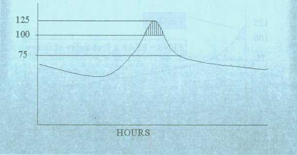
APPENDIX 11 — LOAD DURATION CURVE
LOAD DURATION CURVE
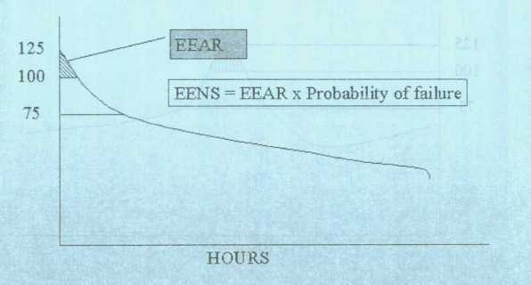
APPENDIX 12 — OPERATION DURING ABNORMAL CONDITIONS
APPENDIX 12: OPERATION DURING ABNORMAL CONDITIONS
| CONDITION FOR USAGE | RESOURCES IN DEFAULT ORDER OF USAGE |
| Warnings | |
| WHEN A SHORTFALL IN CAPACITY IS EXPECTED TO OCCUR, ISSUE WARNINGS UNTIL SUFFICIENT CAPACITY IS OBTAINED TO COVER THE SHORTFALLWhen there is an appreciable loss of load leading to increased frequency, issue warnings until load has been restored. |
(a) Emergency Level generation warning (b) load shedding warning (c) Emergency generation reduction (d) Generation plant shut down |
| Gradual frequency decline | |
| IF THE FREQUENCY FALL BE-LOW 50HZ AND ABNORMAL VOLTAGE CONDITION EXISTS |
(e) Run unscheduled generation units (f) Interruptible load shedding (g) Declare emergency to other SAPP Control Areas |
| Rapid Frequency Decline | |
| ENSURE OPERATION OF UNDER-FREQUENCY PROTECTION SCHEMES | (h) Under-frequency relay protection schemes |
APPENDIX 13 — FORMAT FOR PRELIMINARY INCIDENT REPORT
(a) Time of the incident
(b) Location
(c) Plant and/or apparatus directly involved (and not merely affected by the incident)
(d) Description of the incident
(e) Demand (MW) and/or generation (MW) interrupted and duration of interruption
(f) Generating unit – frequency response (MW and Hz correction achieved subsequent to the incident)
(g) Generating unit- MVAr performance (change in output Subsequent to the incident)
(h) Change in tie-line flow, where applicable
(i) Estimated time and date of return to service
(j) Measures taken to prevent/ mitigate recurrence
APPENDIX 14 — DISTRIBUTOR AND END-USE CUSTOMER DATA
Unless otherwise indicated, the following information shall be supplied to the TNSP, prior to connection and then updated as and when changes occur.
(a) Demand data
|
Connection capacity |
Connection capacity required (MW) |
|
Measured and forecast data (annually): |
For each point of supply, the information required is as follows— (i) A 5 and 15-year demand forecast. (See Appendix 9). (ii) A description setting out the basis for the forecast. (iii) The season of peak demand (iv) Quantification of the estimated impact of embedded generation where applicable. (See Appendix 9) |
|
User network data |
(i) Electrical single-line diagram of user network to a level of detail to be agreed with the service- providers, including the electrical characteristics of circuits and equipment (R1, X1, B1, R0, X0, B0, continuous and probabilistic ratings). |
|
(ii) Contribution from customer network to a three-phase short circuit at point of connection (including that from embedded generation if available) |
|
|
(iii) Connection details of all customer transformers, shunt capacitors, shunt reactors etc. connected to the secondary voltage levels of the customer connected the TS. (the requirement here is for data pertaining to the network connecting shunt capacitors, harmonic filters, reactors, SVCs, etc. to the point of supply for purposes of conducting harmonic resonance studies.) |
|
|
(iv) Electrical characteristics of all circuits and equipment at a voltage lower than secondary voltage levels of the customer connected the TS that may form a closed tie between two connection points on the TS. |
|
|
Standby supply data (annually) |
The following information is required from each distributor and end-use customer that can take supply from more than one supply point— (i) Source of standby supply (alternative supply point(s)) (ii) Standby capacity required (MW) |
|
General information |
For each new connection from a distributor or end-use customer, the following information is required— |
|
(i) Number and type of switch-bays required |
|
|
(ii) Load build-up curve (in the case of new end-user plant) |
|
|
(iii) Supply date (start of load build-up) |
|
|
(iv) Temporary construction supply requirements |
|
|
(v) Load type (e.g. arc furnaces, rectifiers, rolling mills, residential, commercial, etc.) |
|
|
(vi) Annual load factor |
|
|
(vii) Power factor (including details of harmonic filters and power factor correction capacitors) |
|
|
(viii) Special requirements (e.g. QOS) |
|
|
(ix) Other information reasonably required by the service-providers to provide the customer with an appropriate supply (e.g. pollution emission levels for insulation design) |
|
|
Disturbing loads |
Description of any load on the power system that could adversely affect the SO target conditions for power quality and the variation in the power quality that can be expected at the point connected to the TS. (The areas of concern here are, firstly, motors with starting currents referred back to the nominal voltage at the point of supply exceeding 5% of the fault level at the point of supply and secondly, are furnaces likely to produce flicker levels at the point of supply in excess of the limits specified in ZS387 Electricity Supply – Power Quality and Reliability standard. The size limit for arc furnaces is subject to local conditions in respect of fault level at the point of supply and background flicker produced by other arc furnaces and other equipment that will produce harmonics and/or negative and zero sequence current components, such as large AC/DC rectification installations.) |
(a) Transmission system connected transformer data
|
|
Symbol |
Units |
|
Number of windings |
|
|
|
Vector group |
|
|
|
Rated current of each winding |
|
A |
|
Transformer rating |
|
MVATrans |
|
Transformer tertiary rating |
|
MVA |
|
Transformer nominal LV voltage |
|
kV |
|
Transformer nominal tertiary voltage |
|
kV |
|
Transformer nominal HV voltage |
|
kV |
|
Tapped winding |
|
HV/MV/LV/None |
|
Transformer ratio at all transformer taps |
|
|
|
Transformer Impedance (resistance R and reactance X) at all taps |
R+jX |
% on rating MVATrans |
|
For three-winding transformers, where there are external connections to all three windings, the impedance (resistance R and reactance X) between each pair of windings is required, measured with the third set of terminals open-circuit. |
Zhv/mv, ZHVLV, & ZMVLV |
% on rating MVATrans % on rating MVATrans % on rating MVATrans |
|
Transformer zero sequence impedances at nominal tap |
||
|
Zero phase sequence impedance measured between the HV terminals (shorted) and the neutral terminal, with the LV terminals open-circuit. |
ZHT0 |
Ohm |
|
Zero phase sequence impedance measured between the shorted HV terminals and the neutral terminal, with the LV terminals short-circuited to the neutral. |
ZHL0 |
Ohm |
|
Zero phase sequence impedance measured between the LV terminals (shorted) and the neutral terminal, with the HV terminals open-circuit. |
ZLT0 |
Ohm |
|
|
|
|
|
Zero phase sequence impedance measured between the LV terminals (shorted) and the neutral terminal, with the HV terminals short-circuited to the neutral. |
ZLH0 |
Ohm |
|
Zero phase sequence leakage inpedance measured between the HV terminals (shorted) and the LV terminals (shorted), with the Delta winding closed. |
ZL0 |
Ohm |
|
Earthing arrangement, including LV neutral earthing resistance and reactance core construction (number of limbs, shell or core type) |
|
|
|
Open circuit characteristic |
|
Graph |
Transformer test certificates, from which actual technical detail can be extracted as required, are to be supplied on request.
(c) Shunt capacitor or reactor data requirements
For each shunt capacitor or reactor or power factor correction equipment or harmonic filters with a rating in excess of 10MVAr connected to or capable of being connected to a customer network, the customer shall inform and provide the TNSP with the specific shunt capacitor or reactor data as well as network details necessary to perform primarily harmonic resonance studies. The customer shall inform the TNSP of his intention to extend or modify this equipment.
If any participant finds that a capacitor bank of 10MVAr or less is likely to cause harmonic resonance problems on the TS, he shall inform the TNSP. The 10MVAr minimum size limit shall thereafter be waived in respect of the affected network for information reporting purposes in respect of this code, and the TNSP shall inform the affected participants of this fact and request the additional data. If the affected network is modified or reinforced to the extent that capacitor banks of 1 0MVAr or less no longer cause harmonic resonance problems on the TS, the TNSP shall inform the affected participants that information reporting requirements have returned to normal.
Any party to this code investigating a complaint about harmonic distortion, shall have the right to request such additional information (including, but not restricted to, data from harmonic distortion measuring devices) from parties in the vicinity of the source of the complaint as may reasonably be required to complete the investigation.
| Shunt capacitor or reactor rating | Rating (MVAr) |
|
Reactor/capacitor/harmonic filter1 |
|
|
Location (station name) |
|
|
Voltage rating |
kV |
|
Resistance/reactance/susceptance2 of all |
|
|
components of the capacitor or reactor bank |
|
|
Fixed or switched |
|
|
If switched |
Control details (manual, time, load, voltage, etc.) |
|
If automatic control |
Details of settings. If under FACTS device control (e.g. SVC), which device? |
(d) Series capacitor or reactor data requirements
Series capacitors are installed in long transmission lines to increase load transfer capability.
Series reactors are installed to limit fault levels, or to balance load sharing between circuits operated in parallel that would otherwise not share load equitably, or to balance load sharing on an interconnected network.
|
Reactor/capacitor2 |
|
|
|
LOCATION (SPECIFY SUBSTATION BAY WHERE APPLICABLE) |
|
|
|
Voltage rating |
kV |
|
|
Impedance rating |
Ohm or MVAr |
|
|
Current rating (continuous and emergency, maximum times for emergency ratings) |
Continuous: |
A |
|
Hours |
A |
|
|
Hours |
A |
|
|
Hours |
A |
Note: if a series capacitor or reactor is located in a dedicated reactor or capacitor station (i.e. a substation built to hold only the series reactor or capacitor), the lines or cables linking it to each remote end substation must be specified as separate circuits under line or cable data.
1. FACTS DEVICES
FACTS devices enable system parameters (voltage, current, power flow) to be accurately controlled in real time. Because of their cost, they are generally used only if cheaper, more conventional, solutions cannot deliver the required functionality.
Applications requiring rapid control capability include the following—
(a) Voltage regulation following loss of a system component, generation, large load;
(b) Arc furnace voltage flicker mitigation;
(c) Negative phase sequence voltage compensation;
(d) SSR damping;
(e) Machine transient stability enhancement;
(f) System load transfer capability enhancement;
(g) Load sharing control in interconnected, deregulated, networks.
The most commonly used FACTS device is the SVC. Other FACTS devices made possible by advances in power electronics and control systems include STATCON, TCSC, thyristor controlled tap changer, thyristor controlled phase shifter, BES (Battery Energy Storage), and UPC. The common factor is rapid control capability.
Because FACTS devices are purpose-designed for their specific applications, the following data is required:
|
Name |
Station, HV voltage, device number |
|
Type |
(SVC, STATCON, TCSC, etc.) |
|
Configuration: Provide a single line diagram showing all HV components and their MVA/MVAr and voltage ratings, with all controlled components identified as such. |
|
|
Control system: Provide a block diagram of the control system suitable for dynamics modelling. |
|
|
Primary control mode |
Voltage control, arc furnace flicker mitigation, negative phase sequence voltage control, etc. |
Customers are required to perform, or cause to be performed, harmonic studies to ensure that their installation does not excite harmonic resonance, and that harmonic distortion levels at the PCC with the TS do not exceed the limits specified in ZS 387 Electricity Supply – Quality and Reliability standard.
2. HVDC
HVDC is a form of FACTS device because of the rapid control capabilities. However, HVDC is treated separately because its primary function is the transmission of real power.
HVDC is used to connect two systems that are not necessarily interconnected via the AC network (and thus in synchronism), or even at the same nominal frequency.
Customers wishing to connect HVDC systems to the TS shall supply a single line diagram showing all HV plant (including valve bridges) forming part of the HVDC system, plus additional HV plant required for its proper operation, e.g. harmonic filters, synchronous condensers, FACTS devices, etc. Customers and the TNSP shall co-operate in performing, or causing to be performed, studies to determine network-strengthening requirements needed to accommodate the HVDC system without violating the planning criteria specified in the Network Chapter. In addition, customers shall thereafter perform, or cause to be performed, studies to demonstrate that the proposed HVDC system does not exceed QOS parameters specified in ZS387 Electricity Supply – Power Quality and Reliability standard, and where applicable shall specify what additional HV plant will be required to ensure compliance with this standard.
(e) Information on customer networks
If a customer will have two or more points of supply from the TS, including the one applied for, the customer shall specify the amount of load to be transferred from existing points of supply to the new one under normal conditions as well as under contingencies. The same requirement applies to any embedded generators within the customer’s network, since they affect fault levels as well as net load on the system.
The customer shall also specify whether he intends to interconnect two or more transmission points of supply via his network. In such circumstances the customer shall provide detailed information on the lines and cables used.
Where a circuit consists of two or more segments of different characteristics (different overhead line tower and/or conductor bundle types and/or underground cable types), each section shall be specified separately.
|
|
Units |
|
Line description |
Name (“from” busbar, “to” busbar, circuit number and, where applicable, line section number numbered from the “from” bus end) |
|
Line voltage (specify separately for dual voltage multi-circuit lines) |
|
|
kV |
|
|
Single/double/multiple circuit Standard suspension tower information (to confirm impedance): Supply copy of tower drawing, or sketch drawing showing co-ordinates of shield wire and phase conductor bundle attachment points relative to tower centre line and ground level at nominal tower height. |
|
|
Phase sub-conductor type (per circuit) |
|
|
Number of sub-conductors per phase conductor bundle |
|
|
Sub-conductor spacing, if applicable (supply sketch showing phase conductor bundle geometry and attachment point) |
Mm |
|
Number of earth wires Earthwire description Line length |
Km |
|
Conductor parameters (R, X, B, R0, X0, B0) (specify) |
Ohmic values or p.u. on 100MVA base |
|
Conductor normal and emergency ratings voltage |
Ampere or 3 phase MVA at nominal |
Cable data
|
Cable description circuit number, and where |
Name (“from” busbar, “to” busbar, applicable, line section number numbered from the “from” bus end) |
|
Voltage rating |
kV |
|
Type (copper/aluminium) |
(Delete what is not applicable) |
|
Size |
mm2 |
|
Impedance (R, X, B, R0, X0, B0) |
Ohms or p.u. on 100MVA base (specify) |
|
Length |
Km |
|
Continuous and (where applicable) emergency current rating and time limit |
Amp or MVA at nominal voltage (specify), hours maximum at emergency rating |
APPENDIX 15 — GENERATOR PLANNING DATA
Unless otherwise indicated, the following information shall be provided to the TNSP and SO, prior to connection and then updated as and when changes occur.
(a) Power station data
|
Generator name (Owner) |
|
|
Power station name |
|
|
Number of units |
|
|
Primary fuel type/prime mover |
For example gas, hydro, fossil or nuclear |
|
Secondary fuel type |
For example oil |
|
Capacity requirement (MW) |
Generation sent-out connection capacity required |
|
Blackstart Capability |
Contingency plans to restart the generators’ own systems after a total or partial collapse in the network. |
|
Partial load rejection capability |
A description of the amount of load the unit can automatically govern back, without any restrictions, as a function of the load at the point of governing initiation. |
(b) Unit data
|
Unit number |
|
|
Capacity |
Unit capacity (MW) |
|
Normal maximum continuous generation capacity: |
MW |
|
Normal maximum continuous sent out capacity |
MW |
|
Unit auxiliary active load |
MW |
|
Unit auxiliary reactive load |
MVAr |
|
Maximum (EL1) generating capacity |
MW |
|
Maximum (EL2) sent out capacity |
MW |
|
Normal minimum continuous generating capacity |
MW |
|
Normal minimum continuous sent out capacity |
MW |
|
Generator rating (Mbase) |
MVA |
|
Normal maximum lagging power factor |
MVAr |
|
Normal maximum leading power factor |
MVAr |
|
Governor droop |
|
|
Forbidden loading zones |
MW |
|
Terminal voltage adjustment range |
KV |
|
Short circuit ratio |
|
|
Rated stator current |
Amp |
|
Time to synchronise with penstock charged (warm) |
Hour |
|
Time to synchronise with penstock empty from (cold) |
Hour |
|
Normal loading rate |
MW/min |
|
Normal de-loading rate |
MW/min |
|
Partial load rejection capability |
% MW name plate rating |
|
Description |
Data |
|
Capability chart showing full range of operating capability of the generator, including thermal and excitation limits |
Diagram |
|
Open circuit magnetisation curves |
Graph |
|
Short circuit characteristic |
Graph |
|
Zero power factor curve |
Graph |
|
V curves |
Diagram |
|
Documents |
Description |
|
Protection setting document |
A document agreed and signed by the SO containing the following— (i) A section defining the base values and per unit values to be used (ii) A single line diagram showing all the protection functions and sources of current and voltage signals (iii) A protection tripping diagram(s) showing all the protection functions and associated tripping logic and tripping functions (iv) A detailed description of setting calculation for each protection setting, discussion on protection function stability calculations, and detailed dial settings on the protection relay in order to achieve the required setting (v) A section containing a summary of all protection settings on a per unit basis (vi) A section containing a summary for each of the protection relay dial settings/programming details (vii) An annex containing plant information data (e.g. OEM data) on which the settings are based (viii) An annex containing OEM information sheets or documents describing how the protection relays function. |
|
Excitation setting document |
A document agreed and signed by the SO containing the following— (i) A section defining the base values and per unit values to be used (ii) A single line diagram showing all the excitation system functions and all the related protection tripping functions |
|
(iii) An excitation system transfer function block diagram in accordance with IEC standard models (iv) A detailed description of setting calculation for each of the excitation system functions, discussion on function stability calculations, and detailed dial settings on the excitation system in order to achieve the required setting (v) A section containing a summary of all settings on a per unit basis (vi) A section containing a summary for each of the excitation system dial settings/programming details. (vii) An annex containing plant information data (e.g. OEM data) on which the settings are based (viii) An annex containing OEM information sheets or documents describing the performance of the overall excitation system and each excitation function for which a setting is derived. |
|
|
Governor setting document |
A document agreed and signed by the SO containing the following— (i) A section defining the base values and per unit values to be used (ii) A single line diagram showing all the excitation system functions and all the related protection tripping functions (iii) An excitation system transfer function block diagram in accordance with IEC standard models (iv) A detailed description of setting calculation for each of the governor system functions, discussion on function stability calculations, and detailed dial settings on the governor system in order to achieve the required setting (v) A section containing a summary of all settings on a per unit basis (vi) A section containing a summary for each of the governor system dial settings/programming details (vii) An annex containing plant information data (e.g. OEM data) on which the settings are based (viii) An annex containing OEM information sheets or documents describing the performance of the overall governor system and each governor function for which a setting is derived. |
(c) Reserve capability
The generator shall provide the SO with the reserve capability of each power station. The reserve capability shall be indicated as defined in the SAPP Operating Guidelines (1996)
(d) Unit parameters
|
|
Symbol |
Units |
|
Direct axis synchronous reactance |
Xd |
% on rating |
|
Direct axis transient reactance saturated |
X’dsat |
% on rating |
|
Direct axis transient reactance unsaturated |
xdunsat |
% on rating |
|
Sub-transient reactance unsaturated |
x”d=x”q |
% on rating |
|
Quad axis synchronous reactance |
X’q |
% on rating |
|
Quad axis transient reactance unsaturated |
Xqunsat |
% on rating |
|
Negative phase sequence synchronous reactance |
X2 |
% on rating |
|
Zero phase sequence reactance |
X0q |
% on rating |
|
Turbine generator inertia constant for entire rotating mass |
H |
MWs/MVA |
|
Stator resistance |
Ra |
% on rating |
|
Stator leakage reactance |
XL |
% on rating |
|
Poiter reactance |
XP |
% on rating |
|
Generator time constants— |
|
|
|
(i) Direct axis open-circuit transient |
Tdo’ |
sec |
|
(ii) Direct axis open-circuit sub-transient |
Tdo” |
sec |
|
(iii) Quad axis open-circuit transient |
Tqo’ |
sec |
|
(iv) Quad axis open-circuit sub-transient |
Tqo” |
sec |
|
(v) Direct axis short-circuit transient |
Td’ |
sec |
|
(vi) Direct axis short-circuit sub-transient |
Td” |
sec |
|
(vii) Quad axis short-circuit transient |
Tq’ |
sec |
|
(viii) Quad axis short-circuit sub-transient |
Tq” |
sec |
|
Speed damping |
D |
|
|
Saturation ratio at 1 pu terminal voltage |
S(1.0) |
|
|
Saturation ratio at 1.2 pu terminal voltage |
S(1.2) |
(e) Excitation system
The generator shall fill in the following parameters or supply a Laplace-domain control block diagram in accordance with IEEE or IEC standard excitation models (or as otherwise agreed with the SO) completely specifying all time constants and gains to fully explain the transfer function from the compensator or unit terminal voltage and field current to unit field voltage. Customers shall perform, or cause to be performed, small signal dynamic studies to ensure that the proposed excitation system and turbine governor do not cause dynamic instability. Where applicable, a PSS (power system stabiliser) shall be included in the excitation system to ensure proper tuning of the excitation system for stability purposes.
|
|
Symbol |
Units |
|
Excitation system type (AC or DC) |
|
Text |
|
Excitation feeding arrangement (solid or shunt) |
|
Text |
|
Excitation system filter time constant |
Tr |
Sec |
|
Excitation system lead time constant |
Tc |
Sec |
|
Excitation system lag time constant |
Tb |
Sec |
|
Excitation system controller gain |
Ka |
|
|
Excitation system controller lag time constant |
Ta |
Sec |
|
Excitation system maximum controller output |
Vmax |
p.u. |
|
Excitation system minimum controller output |
Vmin |
p.u. |
|
Excitation system regulation factor |
Kc C |
|
|
Excitation system rate feedback gain |
Kf |
|
|
Excitation system rate feedback time constant |
Tf |
Sec |
(f) Speed governor system, turbine and boiler models
The generator shall supply a Laplace domain control block diagram in accordance with IEC standard prime mover models for thermal and hydro units (or as otherwise agreed with the TNSP), fully specifying all time constants and gains to fully explain the transfer function for the governor, turbine, penstocks and control systems in relation to frequency deviations and set point operation.
(g) Control devices and protection relays
The generator should supply any additional Laplace domain control diagrams for any outstanding control devices (including power system stabilisers) or special protection relays in the unit that automatically impinge on its operating characteristics within 30 seconds following a system disturbance and that have a minimum time constant of at least 0,02 seconds.
(h) Unit step-up transformer
|
|
Symbol |
Units |
|
Number of windings |
|
|
|
Vector group |
|
|
|
Rated current of each winding |
|
Amps |
|
Transformer rating |
|
MVAtrans |
|
Transformer nominal LV voltage |
|
kV |
|
Transformer nominal HV voltage |
|
kV |
|
Tapped winding |
|
|
|
Transformer ratio at all transformer taps |
|
|
|
Transformer impedance at all taps (For three winding transformers the HV/LV1, HV/LV2 and LV1/LV2 impedances together with associated bases shall be provided) |
|
% on rating MVATrans |
|
Transformer zero sequence impedance at nominal tap |
Z0 |
Ohm |
|
Earthing arrangement, including neutral earthing resistance and reactance |
|
|
|
Core construction (number of limbs, shell or core type) |
|
|
|
Open circuit characteristic |
|
Graph |
(j) Unit forecast data
The generator shall provide the TNSP and SO with expected maintenance requirements, in weeks per annum, for each unit at a power station.
(k) Return to service of mothballed generating plant
Once the customer has decided to return mothballed generating plant to service, the TNSP requires the information specified for new connections.
(I) Decommissioning of generating plant
Decommissioning of plant is the permanent withdrawal from service of generating plant. The TNSP requires the following with a one-year notice period:
|
Generator name |
|
|
Power station name |
|
|
Unit number |
|
|
Date to be removed from commercial service |
|
|
Auxiliary supplies required for dismantling and demolition |
kVA, point at which supply is require, duration |
APPENDIX 16 — GENERATOR MAINTENANCE DATA
(a) The 52-weeks-ahead outage plan per week per generator shall be updated weekly to the SO in the format shown below:
Annual Maintenance Schedule
Station Name: …………………………………..
|
Week |
||||||||||
| Unit No. | MW lost | 1 | 2 | 3 | 4 | 5 | n+51 | |||
| 1 | Annual Maintenance | 100 | ||||||||
| 2 | Annual Maintenance | 100 | ||||||||
| 2 | Governor modernisation | 100 | ||||||||
| 3 | Transformer oil | 150 | ||||||||
| ETC. | ||||||||||
(b) The annual maintenance/outage plan per generator, looking 15 years ahead, shall also be supplied to the SO. The format shall be quarterly based as follows:
Five Year Ahead Maintenance Schedule
Station Name: ……………………………………
|
Years |
| 1 | 2 | 3 | 4 | 5 | 15 | 15+1 | 15+n | ||||||
| Unit No. | Activity | MW lost | |||||||||||
| 1 | Annual Maintenance | ||||||||||||
| 2 | Annual Maintenance | ||||||||||||
| 2 | Governor modernisation | ||||||||||||
| 3 | Transformer oil |
(c) A weekly variance report, explaining the differences between the planned and actual outages, shall be supplied to the SO as shown below:
| End Date | Reason for difference | ||||
| Outage | Start Date | ||||
| Unit No. | Description | Plan | Actual | Plan | Actual |
APPENDIX 17 — INFORMATION REQUIREMENTS FOR UPGRADING OF EXISTING CONNECTIONS AND NEW CONNECTIONS
|
Commissioning |
Projected or target commissioning test date |
|
Operating |
Target operational or on-line date |
|
Reliability of connection requested |
Number of connecting circuits e.g. one or two feeders, or firm/non-firm supply required (subject to Network chapter requirements) |
|
Location map |
Upgrades: Name of existing point of supply to be upgraded and supply voltage. |
|
New connections: Provide a 1:50 000 or other agreed scale location map, with the location of the facility clearly marked. In addition, specify the co-ordinates of the point of connection. |
|
|
Site plan |
Provide a plan of the site (with at least 1:200 or 1:500) of the proposed facility, with the proposed point of supply, and where applicable, the transmission line route from the facility boundary to the point of supply, clearly marked. |
|
Electrical single-line diagram |
Provide an electrical single-line diagram, drawn to the relevant IEC standard, of the customer intake substation. |
APPENDIX 18 — GENERATOR HV YARD INFORMATION
The TNSP shall provide the following information to Generators about equipment and systems installed in generator HV yards. The TNSP and the SO shall provide the stability criteria.
|
Equipment |
Requirement |
|
Circuit breaker |
MCR rating, peak rating, operating time, OEM, installation date |
|
CT and VT |
CT and VT ratings, classes of equipment, burdening, OEM, installation date |
|
Surge arrestor |
OEM, age, installation date, number of operations |
|
Protection |
Description of protection philosophy for all protection schemes and functions installed, including ARC. Protection reliability information shall be available annually |
|
Power consumption |
List of power consumption requirement by equipment requiring supply from AC, DC and UPS |
|
Link |
MCR rating, peak rating, OEM, installation date |
|
Outgoing Feeder |
MCR rating, peak rating, erection date, length, impedance, transposition characteristics, thermal limits, installed protection, shielding. |
|
Transformer |
Transformer specifications for coupling transformers in HV yards. The records of coupling transformers in HV yards must be available on request. |
|
Compressed air system |
Compressed air system specifications including schematic drawings |
|
Fault recorder |
Fault recorder specifications including resolution, record time, triggering criteria, data format shall be provided on request The TNSP shall review the fault levels and impedance to network centre from HV yard annually. |
APPENDIX 19 — OPERATIONAL DATA
This appendix specifies the data format to be used by the SO,DA system for the mapping of RTU data into the SCADA database. The database has a definition for each electrical configuration (ELC) or electrical object in the station. Each ELC definition specifies a different ELC type, e.g. transformers, units, feeders, etc, and is accompanied by a picture showing the ELC and all its associated devices as they would be indicated on the SO operational one-line displays. In each instance, the picture defines the primary devices and is followed by the points belonging to each device.
DESCRIPTION OF TABLE COLUMN HEADINGS USED IN THIS SECTION
The headings in the tables of this section are described as follows—
(a) Device Gives the name of the device and acts as a collector of all point information belonging to the device.
Each binary status point can be mapped to one or two binary bits. In the case of a breaker or SO lator, the state is reported via two bits. In the case of single-bit alarm points, only one bit is used to report the state of the indication.
01_state This is the alarm state of the point.
10_state This is the normal state of the point.
In the table above the TYPE column indicates the number of bits used to report the state of the point in question.
For single-bit points please ignore the left-hand 0 or 1 value in the headings “01-State” and “10-State”.
Where an indication uses two bits to report the state, the right-hand bit is used report that the state is OPEN and the left-hand bit to report the state when it is CLOSED. Thus an open condition will be “01” and a closed state will be “10”.
It is thus illogical for a device to have a permanent value of either “00” or “11”. However, if the device is in transit between “01” and “10” then a temporary value of “00” is possible. The SCADA system reports a state of “00” as “In transit”, which will normally only be seen on slow-moving devices such as Isolators.
(b) Category defines the category the point belongs to: Health, Main Protection, Back- up Protection or Information.
Classical alarm systems attempt to set priorities on alarm points. However, the priority of a point changes as the system changes, which means having a fixed priority is not useful. As an alternative, the approach used here is to assign the point to the area that is affected by the indication. In this case we have four areas, namely:
|
Health |
All alarm indications that refer to the health of the primary or secondary plant are assigned to this category. |
|
Main Protection |
All protection activity that is triggered by the Main 1 protection circuits is assigned to this category. |
|
Backup Protection |
Where back-up protection is installed, such as on transformers, or where Main 2 protection is used, these alarms are assigned to this category. |
|
Information |
Pure state change data such the state of a breaker or Isolator are assigned to this category. As such, no alarming is associated with these points – the data presented is pure information. |
(c) Type Indicates the type of point – single-bit, double-bit, analogue or binary change detection.
(d) Control Indicates if there is a supervisory control associated with the point
A5.1 Generator
The generator shall install operational measurements to specification from the SO so as to provide continuous operational information for both real time and recording purposes in relation to each unit at each power station in respect of the following—
Unit Isolator
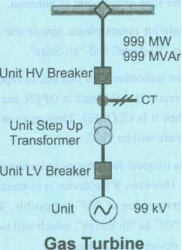
| Unit isolator | 01_State | 10_State | Category | Type | Control |
| Pole | Disagree | Normal | Health | Single | False |
| Unit isolator state | Open | Closed | Info | Double | False |
| Unit HV Breaker | 01 State | 10_ State | Category | Type | Control |
| Breaker failed to trip | Alarm | Normal | Main | Single | False |
| Bus zone trip | Alarm | Normal | Info | Single | False |
| Earth applied | Alarm | Normal | Health | Single | False |
| Pole | Disagree | Normal | Health | Single | False |
| Protection abnormal | Alarm | Normal | Health | Single | False |
| Protection operated | Alarm | Normal | Main | Single | False |
| Protection unhealthy | Alarm | Normal | Health | Single | False |
| Breaker gas critical | Alarm | Normal | Health | Single | False |
| Breaker non-urgent | Alarm | Normal | Info | Single | False |
| Unit breaker state | Closed | Tripped | Info | Double | False |
| CT | 01_State | 10_State | Category | Type | Control |
| SF6 gas critical (CT) | Alarm | Normal | Health | Single | False |
| SF6 non-critical (CT) | Alarm | Normal | Health | Single | False |
| Unit Step Up Transformer | 01_State | 10_State | Category | Type | Control |
| Reactive power | Info | Analogue | False | ||
| Active power | Info | Analogue | False | ||
| Unit LV Breaker | 01 Slate | 10_State | Category | Type | Control |
| Breaker failed to trip | Alarm | Normal | Main | Single | False |
| Earth applied | Alarm | Normal | Health | Single | False |
| Pole | Disagree | Normal | Health | Single | False |
| Breaker gas critical | Alarm | Normal | Health | Single | False |
| Breaker non-urgent | Alarm | Normal | Info | Single | False |
| Unit breaker state | Closed | Tripped | Info | Double | False |
| Unit | 01_State | 10_State | Category | Type | Control |
| Engine A | Ready | Not ready | Health | Single | False |
| Engine B | Ready | Not ready | Health | Single | False |
| Frequency | Info | Analogue | False | ||
| Unit start not ready | Alarm | Normal | Health | Single | False |
| Remote control | On | Off | Info | Single | True |
| SCO start not ready | Alarm | Normal | Health | Single | False |
| Sequence starting | Auto | Manual | Info | Single | False |
| Stator voltage | Info | Analogue | False | ||
| Supervisory | Isolated | Off | Info | Single | False |
| Under-frequency start | Armed | Off | Health | Single | False |
| Unit at standstill | Yes | Normal | Info | Single | True |
| Unit auto load to base | Yes | No | Info | Single | True |
| Unit auto load to minimum | Yes | No | Info | Single | True |
| Unit auto load to peak | Yes | No | Info | Single | True |
| Unit failed to start | Alarm | Normal | Health | Single | False |
| Unit voltage | Info | Analogue | False | ||
| Unit in generation mode | Yes | No | Info | Single | True |
| Unit in SCO mode | Yes | No | Info | Single | True |
| Unit load rate | Fast | Slow | Info | Single | True |
| Unit loading mode | Auto | Manual | Info | Single | False |
| Unit reactive power | |||||
| generated | Info | Analogue | False | ||
| Unit reactive power sent out | Info | Analogue | False | ||
| Unit active power generated | Info | Analogue | False | ||
| Unit active power sent out | Info | Analogue | False | ||
| Unit tripped and locked out | Alarm | Normal | Info | Single | False |
| Unit under frequency start | Initiate | No | Info | Single | False |
(b) Hydro units
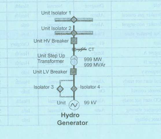
| Unit Isolator 1 | 01_State | 10_State | Category | Type | Control |
| Pole | Disagree | Normal | Health | Single | False |
| Unit Isolator state | Open | Closed | Info | Double | False |
| Unit Isolator 2 | 01_State | 10_State | Category | Type | Control |
| Pole | Disagree | Normal | Health | Single | False |
| Unit Isolator state | Open | Closed | Info | Double | False |
| Unit HV Breaker | 01_State | 10_State | Category | Type | Control |
| Breaker failed to trip | Alarm | Normal | Main | Single | False |
| Bus zone trip | Alarm | Normal | Info | Single | False |
| Earth applied | Alarm | Normal | Health | Single | False |
| Pole | Disagree | Normal | Health | Single | False |
| Protection abnormal | Alarm | Normal | Health | Single | False |
| Protection operated | Alarm | Normal | Main | Single | False |
| Protection unhealthy | Alarm | Normal | Health | Single | False |
| Breaker gas critical | Alarm | Normal | Health | Single | False |
| Breaker non-urgent | Alarm | Normal | Info | Single | False |
| Unit breaker state | Closed | Tripped | Info | Double | False |
| CT | 01_State | 10_State | Category | Type | Control |
| SF6 gas critical (CT) | Alarm | Normal | Health | Single | False |
| SF6 non-critical (CT) | Alarm | Normal | Health | Single | False |
| Unit LV Breaker | 01_State | 10_State | Category | Type | Control |
| Breaker failed to trip | Alarm | Normal | Main | Single | False |
| Earth applied | Alarm | Normal | Health | Single | False |
| Pole | Disagree | Normal | Health | Single | False |
| Breaker gas critical | Alarm | Normal | Health | Single | False |
| Breaker non-urgent | Alarm | Normal | Info | Single | False |
| Unit breaker state | Closed | Tripped | Info | Double | False |
| Unit Step Up Transformer | 01 State | 10_State | Category | Type | Control |
| Reactive power | Info | Analogue | False | ||
| Active power | Info | Analogue | False | ||
| Isolator 3 | 01_State | 10_State | Category | Type | Control |
| Pole | Disagree | Normal | Health | Single | False |
| Unit Isolator state | Open | Closed | Info | Double | False |
| Isolator 4 | 01_State | 10_State | Category | Type | Control |
| Pole | Disagree | Normal | Health | Single | False |
| Unit Isolator state | Open | Closed | Info | Double | False |
| Unit | 01_State | 10_State | Category | Type | Control |
| Frequency | Info | Analogue | False | ||
| Auto load | Active | Normal | Info | Single | True |
| Automatic power factor | |||||
| regulator | Operated | Normal | Health | Single | True |
| Emergency trip | Operated | Normal | Main | Single | True |
| Unit start not ready | Alarm | Normal | Health | Single | False |
| Unit to pump mode | Active | Off | Info | Single | True |
| Unit to SCO mode | Active | Off | Info | Single | True |
| Pump start not ready | Alarm | Normal | Health | Single | False |
| Pump to generation mode | Active | Off | Info | Single | True |
| Pump to SCO mode | Active | Off | Info | Single | True |
| SCO start not ready | Alarm | Normal | Health | Single | False |
| SCO to generation mode | Active | Off | Info | Single | True |
| SCO to pump mode | Active | Normal | Info | Single | True |
| Sequence starting | Auto | Manual | Info | Single | False |
| Stator voltage | Info | Analogue | Log only | No | |
| Under – frequency start | Armed | Off | Health | Single | False |
| Unit AGC – high limit | High | Normal | Health | Single | False |
| Unit AGC – high regulating limit | Health | Analogue | Panel | No | |
| Unit AGC – low limit | Low | Normal | Health | Single | False |
| Unit AGC – low regulating limit | Health | Analogue | False | ||
| Unit AGC – raise/lower | |||||
| blocking | Off | Normal | Info | Single | False |
| Unit AGC – ramp rate | Info | Analogue | False | ||
| Unit AGC – set-point active power | Info | Analogue | True | ||
| Unit AGC – status | On | Off | Info | Single | False |
| Unit at standstill | Yes | Normal | Info | Single | True |
| Unit voltage | Info | Analogue | False | ||
| Unit guide vane | Info | Analogue | True | ||
| Unit in generation mode | Yes | No | Info | Single | True |
| Unit in pump mode | Yes | No | Info | Single | True |
| Unit in SCO mode | Yes | No | Info | Single | True |
| Unit load limiter | Info | Analogue | True | ||
| Unit reactive power generated | Info | Analogue | False | ||
| Unit reactive power sent out | Info | Analogue | False | ||
| Unit active power generated | Info | Analogue | False | ||
| Unit active power sent out | Info | Analogue | False | ||
| Unit synchronising | Yes | No | Info | Single | False |
| Unit turning in generation | |||||
| direction | Yes | No | Info | Single | False |
| Unit turning in motor | |||||
| direction | Yes | No | Info | Single | False |
(c) Steam units
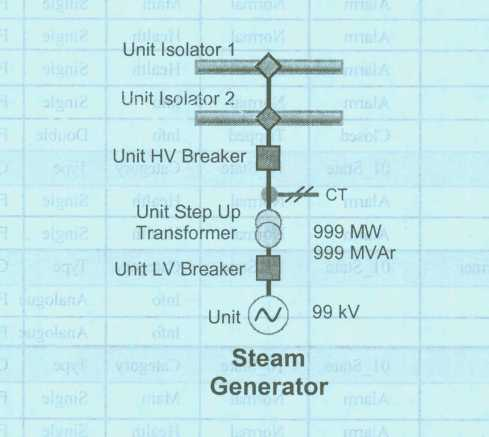
|
Unit isolator 1 |
01_State |
10_State |
Category |
Type |
Control |
|
Pole |
Disagree |
Normal |
Health |
Single |
False |
|
Unit Isolator state |
Open |
Closed |
Info |
Double |
False |
|
Unit Isolator 2 |
01_State |
10_ State |
Category |
Type |
Control |
|
Pole |
Disagree |
Normal |
Health |
Single |
False |
|
Unit Isolator state |
Open |
Closed |
Info |
Double |
False |
|
Unit HV Breaker |
01_State |
10_State |
Category |
Type |
Control |
|
Breaker failed to trip |
Alarm |
Normal |
Main |
Single |
False |
|
Bus zone trip |
Alarm |
Normal |
Info |
Single |
False |
|
Earth applied |
Alarm |
Normal |
Health |
Single |
False |
|
Pole |
Disagree |
Normal |
Health |
Single |
False |
|
Protection abnormal |
Alarm |
Normal |
Health |
Single |
False |
|
Protection operated |
Alarm |
Normal |
Main |
Single |
False |
|
Protection unhealthy |
Alarm |
Normal |
Health |
Single |
False |
|
Breaker gas critical |
Alarm |
Normal |
Health |
Single |
False |
|
Breaker non-urgent |
Alarm |
Normal |
Info |
Single |
False |
|
Unit breaker state |
Closed |
Tripped |
Info |
Double |
False |
|
CT |
01_State |
10_State |
Category |
Type |
Control |
|
SF6 gas critical (CT) |
Alarm |
Normal |
Health |
Single |
False |
|
SF6 non-critical (CT) |
Alarm |
Normal |
Health |
Single |
False |
|
Unit Step Up Transformer |
01_State |
10_State |
Category |
Type |
Control |
|
Reactive power |
|
|
Info |
Analogue |
False |
|
Active power |
|
|
Info |
Analogue |
False |
|
Unit LV Breaker |
01 _State |
10_State |
Category |
Type |
Control |
|
Breaker failed to trip |
Alarm |
Normal |
Main |
Single |
False |
|
Earth applied |
Alarm |
Normal |
Health |
Single |
False |
|
Pole |
Disagree |
Normal |
Health |
Single |
False |
|
Breaker gas critical |
Alarm |
Normal |
Health |
Single |
False |
|
Breaker non-urgent |
Alarm |
Normal |
Info |
Single |
False |
|
Unit breaker state |
Closed |
Tripped |
Info |
Double |
False |
|
Steam Unit |
01_state |
10_State |
Category |
Type |
Control |
|
Unit AGC – high limit |
High |
Normal |
Health |
Single |
False |
|
Unit AGC – high regulating limit |
|
Health |
Analogue |
False |
|
|
Unit AGC – low limit |
Low |
Normal |
Health |
Single |
False |
|
Unit AGC – low regulating limit |
|
Health |
Analogue |
False |
|
|
Unit AGC – raise/lower blocking |
Off |
Normal |
Info |
Single |
False |
|
Unit AGC – ramp rate |
|
|
Info |
Analogue |
False |
|
Unit AGC – set-point active power |
|
Info |
Analogue |
True |
|
|
Unit AGC – status |
On |
Off |
Info |
Single |
False |
|
Unit voltage |
|
|
Info |
Analogue |
False |
|
Unit islanded |
Alarm |
No |
Health |
Single |
False |
|
Unit reactive power generated |
|
|
Info |
Analogue |
False |
|
Unit reactive power sent out |
|
|
Info |
Analogue |
False |
|
Unit active power generated |
|
|
Info |
Analogue |
False |
|
Unit active power sent out |
|
|
Info |
Analogue |
False |
Generators contributing to regulating reserve shall provide indications for emergency generation and maximum generation for rescheduling.
A5.2 Distributor and end-use customer
(a) Transmission equipment
The Customer shall provide operational information for both real time and recording purposes in relation to each feeder, transformer and compensation device at each substation required for the full functionality of a SVC, as well as full control by the SO.
Interruptible Load
All interruptible loads shall meet the minimum requirements. The SO shall negotiate and integrate the conditions as presented in bilateral agreements and additional contracts without reducing the requirements as defined in this Grid Code.
The interruptible load shall install operational measurements to specification so as to provide operational information for both real time and recording purposes in relation to each controllable energy block in respect of the following minimum requirements for operation and control of a interruptible load:
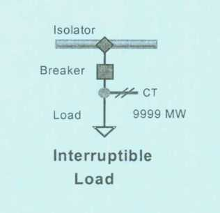
|
Isolator |
01_State |
10_State |
Category |
Type |
Control |
|
Pole |
Disagree |
Normal |
Health |
Single |
False |
|
Isolator state |
Closed |
Open |
Info |
Double |
False |
|
Breaker |
01_State |
10_State |
Category |
Type |
Control |
|
Unit breaker state |
Closed |
Tripped |
Info |
Double |
True |
|
CT |
01_State |
10_State |
Category |
Type |
Control |
|
SF6 gas critical (CT) |
Alarm |
Normal |
Health |
Single |
False |
|
SF6 non-critical (CT) |
Alarm |
Normal |
Health |
Single |
False |
|
Load |
01_State |
10_State |
Category |
Type |
Control |
|
Load reduction acknowledged |
No |
Yes |
Info |
Single |
True |
|
Load interrupt acknowledged |
No |
Yes |
Info |
Single |
True |
|
Block load reduction acknowledged |
No |
Yes |
Info |
Single |
True |
|
Return to service acknowledged |
No |
Yes |
Info |
Single |
True |
|
Load active power |
|
|
Info |
Analogue |
False |
APPENDIX 20 — POST-DISPATCH INFORMATION
The SO shall provide the following minimum operational information in near real-time and as historic data in relation to each power station:
|
No. |
Data description |
Format |
Size |
Unit |
|
1 |
High limit |
Real |
999,99 |
MW |
|
2 |
Low limit |
Real |
999,99 |
MW |
|
3 |
AGC mode CER/BLO |
Character |
3 |
|
|
4 |
AGC status AUT/OFF/MAN |
Character |
3 |
|
|
5 |
Set point |
Real |
99,99 |
MW |
|
6 |
AGC pulse |
Real |
9,9 |
|
|
7 |
Sent-out |
Real |
999,99 |
MW |
|
8 |
Auxiliary |
Real |
999,99 |
MW |
|
9 |
Contracted Power |
Integer |
999 |
MW |
|
10 |
Station spinning |
Integer |
999 |
|
|
11 |
32-bit flag on AGC settings |
Integer |
|
32 bits |
The SO shall provide the following minimum operational information in near real-time in relation to the overall dispatch performance:
|
No. |
Data description |
Format |
Size |
Unit |
|
1 |
Area control error (ACE) |
Real |
999,99 |
MW |
|
2 |
Average ACE previous hour |
Real |
999,99 |
MW |
|
3 |
System frequency (Hz) |
Real |
99,999 |
MW |
|
4 |
Frequency distribution current hour |
Real |
999,99 |
MW |
|
5 |
Frequency distribution previous hour |
Real |
999,99 |
MW |
|
6 |
System total generation |
Integer |
99999 |
MW |
|
7 |
Control area total actual interchange |
Integer |
99999 |
MW |
|
8 |
Control area total scheduled interchange |
Integer |
99999 |
MW |
|
9 |
System operating reserve |
Integer |
99999 |
MW |
|
10 |
System sent-out |
Integer |
99999 |
MW |
|
11 |
System spinning reserve |
Integer |
99999 |
MW |
|
12 |
AGC regulating up |
Integer |
99999 |
MW |
|
13 |
AGC regulating down |
Integer |
99999 |
MW |
|
14 |
AGC regulating up assist |
Integer |
99999 |
MW |
|
15 |
AGC regulating down assist |
Integer |
99999 |
MW |
|
16 |
AGC regulating up emergency |
Integer |
99999 |
MW |
|
17 |
AGC regulating down emergency |
Integer |
99999 |
MW |
|
18 |
AGC mode |
Char |
TLBC /CFC |
|
|
19 |
AGC status |
Char |
ON/ OFF |
|
|
20 |
Area control error output |
Real |
999.99 |
MW |
|
21 |
System transmission losses |
Real |
999.99 |
MW |
|
22 |
ZESA tie-lines |
Integer |
99999 |
MW |
|
23 |
DRC tie-lines |
Integer |
99999 |
MW |
|
24 |
BPC radial-line |
Integer |
99999 |
MW |
|
25 |
AGC performance indicators |
|
|
APPENDIX 21 — BACK UP FILES
|
File |
Description |
Trigger Event |
Frequency |
|
AGC pulses |
The total pulses sent to a unit by the AGC system to move the set-point up or down |
Ongoing, file created at end of hour |
Hourly |
|
NERC |
A list of the total NERC “A1” and “A2” criteria violations in the system over an hour |
Ongoing, file appended at end of hour |
Daily |
|
System near real-time data |
Historic near real-time system data files on readings as required for post-dispatch |
Communication failure |
To be agreed |
|
Unit near real-time data |
Historic near real-time unit data files on readings as required for post-dispatch |
Communication failure |
To be agreed |
APPENDIX 22 — GENERATOR PERFORMANCE DATA
Generator performance data is a means of providing a measurement of generating station processes. A combination of different metrics yields indicators that provide an objective assessment of critical parameters on the performance of key processes. They are used to identify non-performing areas in order to facilitate improvements. This is also used to provide industry with statistical data on how well the industry is performing.
The indicators will provide generating stations in Zambia an opportunity to benchmark their performance against other best run hydro power stations in the world. It also offers these station’s management data for strategic management.
The Key Performance Indicators report on each station’s efficiency and effectiveness is at a tactical level. The assumption here is that, even when a generating station is embedded in a vertically integrated utility, it is very possible to measure these statistics against a common benchmark.
For the purpose of these indicators, all generation equipment outages will be considered planned and scheduled at every beginning of the year. All other outages procured during the progression of the year will be considered unplanned.
(a) Reliability
This indicator will be expressed in terms of Unit Capability Factor (UCF). The purpose of this indicator is to monitor progress in attaining high unit and plant energy production availability. It reflects the effectiveness of plant programmes and practices in maximising available electrical generation and provides an overall indication of how well the plant was operated and maintained. It comprises Planned Capability Loss Factor (PCLF) and Unplanned Capability Loss Factor (UCLF) and it is expressed as a difference between 100% and the percentage attributed to PCLF and UCLF.
UCF = 100 – PCLF – UCLF
(i) Unplanned capability loss factor (UCLF)
The purpose of this indicator is to monitor industry progress in minimising outage time and power reductions that result from unplanned equipment failures or other conditions. This indicator reflects the effectiveness of plant programmes and practices in maintaining systems available for safe electrical generation.
It is therefore an expression of energy lost due to unplanned outages, against the total available energy, calculated as a percentage.
| UCLF = | Unplanned MWh lost *100% |
| Total MWhde signed |
(ii) Planned capability loss factor (PCLF)
Planned capability loss factor is defined as the ratio of the planned energy losses during a given period of time to the reference energy generation expressed as a percentage.
Planned energy loss is energy that was not produced during the period because of planned shutdowns or load reductions due to causes under plant management control. Energy losses are considered to be planned if they are scheduled and appear on the System Yearly Maintenance Program. It will stimulate detailed scrutiny and predictability of generating plant so that outages are focused and scheduled one (1) year in advance.
| PCLF = | Planned MWh lost * 100% |
| Total M Wilde signed |
(b) Internal Reliability Loss Factor
This factor is expressed to measure the number of internal factors leading to reduction in Reliability of generating plant against the total reduction in Reliability. It is therefore expressed as a percentage of energy lost due to internal faults leading to lost generation against available energy during the period.
| IRLF= | Unplanned MWh lost due to internal faults * 100% |
| Total MWh available |
(c) External Reliability Loss Factor
This factor measures the influence that external factors leading to forced outages has on the generating plant. Such factors could include transmission line trippings or outages, deferred maintenance activities due to system load changes, cascade trippings and many others. It is expressed as a percentage of energy losses due to faults external to the generating plant, leading to loss of generation against total available energy during the given period.
| ERLF = | Unplanned MWh lost due to external faults * 100% |
| Total MWh Available |
(d) Mean-Time-To-Repair (MTTR)
This factor measures the average time used to carry out repairs due to faults in any given period. It is expressed as the sum of all durations generating units were disconnected from the grid due to internal faults against the total number of breakdowns due to internal faults.
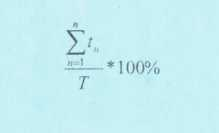
Where;
t = time duration for each internal fault
n = outage number
T is the total number of outages in the period.
(e) Mean-Time-Between-Failures (MTBF)
This is expressed as the total time in a given period divided by the number of internal faults plus 1. It is meant to express on an average the time between any two failures following each other.
Mean-Time-To-Repair and Mean-Time-Between-Failures are two factors that are used to measure the quality of maintenance being carried out on generating plant.
(f) Start-up Failure Rate (SFR)
This is expressed as the number of times a generating unit or plant fails to connect to the grid at the required time against the total number of requested synchronisations. This measure is used to gauge under-frequency recovery time.
| SFR = | Number Of failed Start Ups x 100% |
| Number Of Contracted Start Ups |
Start-up comprises the set of operations that enable the unit to be connected to the off-site power grid for the production of electrical energy according to requirements issued by the SO. It includes all the necessary “de-isolations” and rendering to “normal” all equipment required for generation.
The contracted start-up refers to the number of start-up instructions issued and received from the System Operation by the Generation Control Room.
(g) Total Unplanned Station Shutdowns (TUSS)
This is the total number of times that a generating station separates with the grid. It could either be as a result of an internal or external unplanned factor, but leading to a total station outage. It measures the protection requirements defined in the Network chapter, section 4.1, or it could be declared as an Ancillary Service as declared in the System Operations chapter section 7.
APPENDIX 23 — REPORTING FORMAT FOR PERIODIC TESTING OF UNDER-FREQUENCY LOAD SHEDDING RELAYS
Distributor: ……………………………………
Date: ………………………………………….
Substation: …………………………………..
Fed from transmission substation (directly or indirectly):
|
|
Activating frequency |
Timer setting |
||
|
|
Required |
As tested |
Required |
As tested |
|
Stage 1 |
48.8Hz |
|
Instantaneous |
|
|
Stage 2 |
48.5Hz |
|
Instantaneous |
|
|
Stage 3 |
48.2Hz |
|
Instantaneous |
|
|
Stage 4 |
49.0Hz |
|
20 seconds |
|
|
Stage 5 |
0.8Hz/s |
|
Instantaneous |
|
|
|
Feeders selected (Required) |
Feeders selected (As tested) |
||
|
Stage 1 |
|
|
||
|
Stage 2 |
|
|
||
|
Stage 3 |
|
|
||
|
Stage 4 |
|
(Current SAPP Guidelines)
APPENDIX 24 — PERFORMANCE INDICATORS FOR TNSPS AND SO
|
Indicator |
Month |
Year to date |
12 MMI |
Unit |
|
System minutes lost |
|
|
|
Minutes |
|
No. of Interruptions |
|
|
|
|
|
No. of statutory voltage transgressions |
|
|
|
|
|
Mandatory under-frequency load shedding |
|
|
|
APPENDIX 25 — INFORMATION CONFIDENTIALITY
Confidentiality agreement for information transfer to third parties
Confidentiality Agreement
Between
………………………………………………………………………………………………………………
(Hereinafter referred to as the information owner)
And
………………………………………………………………………………………………………………
(Hereinafter referred to as the recipient)
In respect of information supplied to perform the following work:
………………………………………………………………………………………………………………
(Hereinafter referred to as the work)
On behalf of
………………………………………………………………………………………………………………
(Hereinafter referred to as the client).
1. The Recipient agrees to treat all information (hereinafter referred to as the Information) received from the Information Owner, whether in hard copy or electronic format or in any format whatsoever, as strictly confidential.
2. The Recipient agrees to disclose the Information only to authorised persons who are in his permanent employ, and who require access to the Information to perform their duties in respect of the Work on behalf of the Client.
3. Persons other than those described in Clause 2 above, including but not restricted to temporary employees, sub-contractors, and sub-consultants, shall enter into separate Confidentiality Agreements with the Information Owner prior to receiving the Information.
4. The Recipient undertakes to use the Information only to perform the Work on behalf of the Client, and for no other purpose whatsoever.
5. On completion of the Work, the Recipient shall at his expense return to the Information Owner all hard copy material and electronic media containing the Information supplied to him by the Information Owner. The Recipient shall furthermore ensure that all duplicate copies of the Information in his or his employees’ possession (electronic as well as hard copy format) are destroyed.
6. The Recipient shall take all reasonable measures to protect the security and integrity of the Information.
7. If requested to do so by the Information Owner, the Recipient shall forthwith at his expense return to the Information Owner all hard copy material and electronic media containing the Information supplied to him by the Information Owner. The Recipient shall furthermore ensure that all duplicate copies of the Information in his or his employees’ possession (electronic as well as hard copy format) are destroyed.
8. The Recipient shall report any leak of the Information, howsoever caused, to the Information Owner as soon as practicable after he becomes aware of the leak, and shall provide to the Information Owner with all reasonable assistance to ensure its recovery or destruction (as deemed appropriate by the Information Owner).
Signed at ………………………….. on this the ……………………… day of ……………………… by (full name) …………………………………. in his/her capacity as …………….. on behalf of ………, the Information Owner ……………………………….
Signed at ………………………………… on this the ………………………………… day of ………………………………… by (full name) ………………………………… in his/her capacity as ………………………………… on behalf of …………………………………, the Recipient.
APPENDIX 26 — PLANNING SCHEDULES
Schedule 1: Five and Fifteen-year demand forecast
|
|
Demand = Total Demand + Distribution Losses – Embedded Generation |
|||||
|
|
|
Energy |
Maximum demand |
Expected minimum demand |
||
|
Year |
|
GWh |
MW |
MVAr |
MW |
MVAr |
|
Measured |
|
|
|
|
|
|
|
Year 0 |
||||||
|
Year 1 |
||||||
|
Year 2 |
||||||
|
Year 3 |
||||||
|
Year 4 |
||||||
|
Year 5 |
||||||
|
Year 6 |
||||||
|
Year 7 |
||||||
|
Year 8 |
||||||
|
Year 9 |
||||||
|
Year 10 |
||||||
|
Year 11 |
||||||
|
Year 12 |
||||||
|
Year 13 |
||||||
|
Year 14 |
Schedule 2: Embedded Generation 50MVA
|
Generator |
Tx substation name at closest connection point |
Operating power factor |
Installed capacity |
Plan type |
On-site dosage |
Net sent out |
Generation net sent out contribution at peak |
||||||||||
|
(MW) |
|||||||||||||||||
|
Normal |
Peak |
Normal |
Peak |
Year 1 |
Year 2 |
Year 3 |
Year 4 |
Year 5 |
… |
… |
Year 14 |
Year 15 |
|||||
|
|
|
|
|
|
|
|
|
|
|
|
|
|
|
|
|
|
|
|
|
|
|
|
|
|
|
|
|
|
|
|
|
|
|
|
|
ELECTRICITY (COMMON CARRIER) (DECLARATION) (REVOCATION) ORDER
[Section 15]
Arrangement of Paragraphs
Paragraph
1. Title
2. Revocation of S.I. No. 24 of 2021
SI 94 of 2021.
This Order may be cited as the Electricity (Common Carrier) (Declaration) (Revocation) Order.
2. Revocation of S.I. No. 24 of 2021
The Electricity (Common Carrier) (Declaration) Regulations, 2021, are revoked.